1993 CHEVROLET DYNASTY engine oil
[x] Cancel search: engine oilPage 221 of 2438
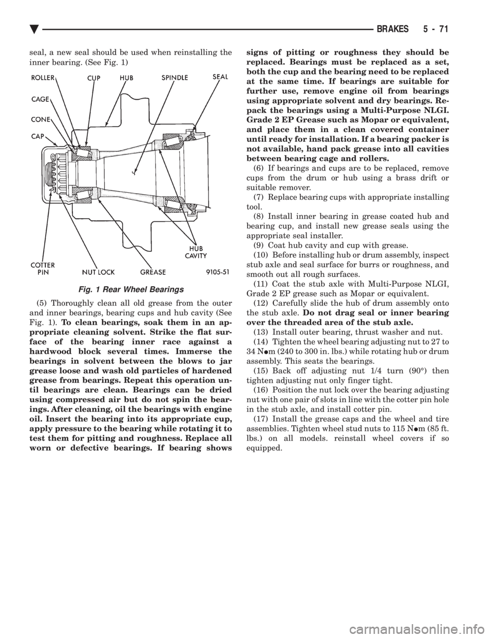
seal, a new seal should be used when reinstalling the
inner bearing. (See Fig. 1) (5) Thoroughly clean all old grease from the outer
and inner bearings, bearing cups and hub cavity (See
Fig. 1). To clean bearings, soak them in an ap-
propriate cleaning solvent. Strike the flat sur-
face of the bearing inner race against a
hardwood block several times. Immerse the
bearings in solvent between the blows to jar
grease loose and wash old particles of hardened
grease from bearings. Repeat this operation un-
til bearings are clean. Bearings can be dried
using compressed air but do not spin the bear-
ings. After cleaning, oil the bearings with engine
oil. Insert the bearing into its appropriate cup,
apply pressure to the bearing while rotating it to
test them for pitting and roughness. Replace all
worn or defective bearings. If bearing shows signs of pitting or roughness they should be
replaced. Bearings must be replaced as a set,
both the cup and the bearing need to be replaced
at the same time. If bearings are suitable for
further use, remove engine oil from bearings
using appropriate solvent and dry bearings. Re-
pack the bearings using a Multi-Purpose NLGI.
Grade 2 EP Grease such as Mopar or equivalent,
and place them in a clean covered container
until ready for installation. If a bearing packer is
not available, hand pack grease into all cavities
between bearing cage and rollers. (6) If bearings and cups are to be replaced, remove
cups from the drum or hub using a brass drift or
suitable remover. (7) Replace bearing cups with appropriate installing
tool. (8) Install inner bearing in grease coated hub and
bearing cup, and install new grease seals using the
appropriate seal installer. (9) Coat hub cavity and cup with grease.
(10) Before installing hub or drum assembly, inspect
stub axle and seal surface for burrs or roughness, and
smooth out all rough surfaces. (11) Coat the stub axle with Multi-Purpose NLGI,
Grade 2 EP grease such as Mopar or equivalent. (12) Carefully slide the hub of drum assembly onto
the stub axle. Do not drag seal or inner bearing
over the threaded area of the stub axle. (13) Install outer bearing, thrust washer and nut.
(14) Tighten the wheel bearing adjusting nut to 27 to
34 N Im (240 to 300 in. lbs.) while rotating hub or drum
assembly. This seats the bearings. (15) Back off adjusting nut 1/4 turn (90É) then
tighten adjusting nut only finger tight. (16) Position the nut lock over the bearing adjusting
nut with one pair of slots in line with the cotter pin hole
in the stub axle, and install cotter pin. (17) Install the grease caps and the wheel and tire
assemblies. Tighten wheel stud nuts to 115 N Im (85 ft.
lbs.) on all models. reinstall wheel covers if so
equipped.
Fig. 1 Rear Wheel Bearings
Ä BRAKES 5 - 71
Page 333 of 2438
MANUAL TRANSAXLE CLUTCH
CONTENTS
page page
CLEANING PRECAUTIONS ................. 6
CLUTCH CABLE MECHANISM .............. 1
CLUTCH CABLE REPLACEMENT ............ 2
CLUTCH CHATTER COMPLAINTS ........... 1
CLUTCH DISC REPLACEMENT ............. 5
CLUTCH PEDAL NOISE/POP ............... 2 CLUTCH PEDAL POSITION SWITCH
......... 4
EXCESSIVE CLUTCH SPIN TIME/CLASH INTO REVERSE COMPLAINTS ............ 1
GENERAL INFORMATION .................. 1
RELEASE BEARING AND FORK ............. 6
GENERAL INFORMATION
Throughout this group, references may be made to
a particular vehicle by letter or number designation.
A chart showing the breakdown of these designations
is included in the Introduction Section at the front of
this service manual. The clutch used in all models are a single, dry disc
type with no adjustment for wear being provided in
the clutch itself. The clutch pedal is connected to the release shaft
through a cable and lever. The upper end of the clutch pedal pivots in the
pedal bracket on two nylon bushings. These bushings
do not require periodic lubrication.
CLUTCH CHATTER COMPLAINTS
For all clutch chatter complaints, do the following:
(1) Check for loose, misaligned, or broken engine
and transmission mounts. If present, they should be
corrected at this time. Test vehicle for chatter. If
chatter is gone, there is no need to go any further. If
chatter persists: (2) Check to see if clutch cable routing is correct
and operates smoothly. (3) Check for loose connections in drive train. Cor-
rect any problems and determine if clutch chatter
complaints has been satisfied. If not, (4) Remove transaxle. See Group 21, Manual Tran-
saxle, for procedure. (5) Check to see if the release bearing is sticky or
binding. Replace bearing, if needed. (6) Check linkage for excessive wear on bushings.
Replace all worn parts. A small amount of bearing
grease between the release shaft bushings and the
shaft is beneficial, but not required. (7) Check flywheel and clutch pressure plate for
contamination (dirt, oil) or scored. Replace flywheel
and/or pressure plate, if required. (8) Check to see if the clutch disc hub splines are
damaged. Replace with new disc. (9) Check input shaft splines for damage. Replace
if necessary. (10) Check for uneven wear on clutch fingers.
EXCESSIVE CLUTCH SPIN TIME/CLASH INTO
REVERSE COMPLAINTS
For all excessive clutch spin time/clash into reverse
complaints, do the following: (1) Depress clutch pedal to floor and hold. After
three seconds, shift to reverse. If clash is present,
clutch has excessive spin time. (2) Remove transaxle. See Group 21, Manual Tran-
saxle, for procedure. (3) Check the input shaft spline, clutch disc splines
and release bearing for dry rust. If present, clean
rust off and apply a light coat of bearing grease to
the input shaft splines. Apply grease on the input
shaft splines only where the clutch disc slides. (4) Check to see if the clutch disc hub splines are
damaged, replace with new disc if required. (5) Check the input shaft for damaged splines. Re-
place as necessary. (6) Check for excessive clutch disc runout or
warpage. (7) Install clutch assembly and transaxle.
CLUTCH CABLE MECHANISM
The manual transaxle clutch release system has a
unique self-adjusting mechanism to compensate for
clutch disc wear. This adjuster mechanism is located
within the clutch pedal. The preload spring main-
tains tension on the cable. This tension keeps the
clutch release bearing continuously loaded against
the fingers of the clutch cover assembly. When the pedal is depressed, teeth on the adjuster
and the positioner engage and pull the release cable.
A spring located behind the adjuster ensures proper
tooth engagement. When the pedal is released, the adjuster contacts
the bumper. This separates the adjuster and posi-
tioner teeth, allowing the preload spring to function.
Ä MANUAL TRANSAXLE CLUTCH 6 - 1
Page 336 of 2438
CLUTCH PEDAL POSITION SWITCH
The clutch pedal position switch functions as a
safety interlock device. It prevents possible engine
cranking with the clutch engaged. The clutch pedal position switch is wired in series
between the starter relay coil and the ignition
switch. The clutch pedal position switch is mounted to a
bracket located next to the clutch pedal. The switch
is held in place by four plastic wing tabs. The clutch pedal position switch has an adjustable
striker plate. The striker plate is located on the left
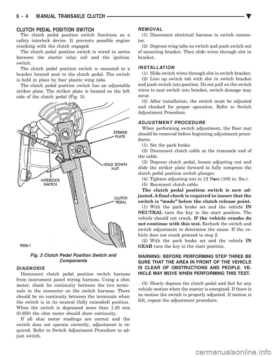
side of the clutch pedal (Fig. 3).
DIAGNOSIS
Disconnect clutch pedal position switch harness
from instrument panel wiring harness. Using a ohm
meter, check for continuity between the two termi-
nals in the connector on the switch harness. There
should be no continuity between the terminals when
the switch is in its neutral (fully extended) position.
When the switch is depressed more than 1.25 mm
(0.050) the ohm meter should show continuity. If all ohm meter readings are correct and the
switch does not operate correctly, adjustment is re-
quired. Refer to Switch Adjustment Procedure to ad-
just switch.
REMOVAL
(1) Disconnect electrical harness to switch connec-
tor. (2) Depress wing tabs on switch and push switch out
of mounting bracket. Then slide wires through slot in
bracket.
INSTALLATION
(1) Slide switch wires through slot in switch bracket.
(2) Line up switch tab with slot in switch bracket
and push switch into position. Do not pull on the switch
wires to seat switch into bracket, switch damage may
occur. (3) After installation, the switch must be adjusted
and checked for proper operation. Refer to Switch
Adjustment Procedure.
ADJUSTMENT PROCEDURE
When performing switch adjustment, the floor mat
should be removed before beginning adjustment proce-
dures. (1) Set the park brake.
(2) Disconnect clutch cable at the transaxle end of
the cable. (3) Depress clutch pedal, loosen adjusting nut and
slide the striker plate forward to fully compress the
clutch pedal position switch plunger. (4) Tighten adjusting nut to 12 N Im (105 in. lbs.).
(5) Reconnect clutch cable.
The clutch pedal position switch is now ad-
justed. A final check is required to insure that the
switch is ``made'' below the clutch release point. (1) With the park brake set and the vehicle IN
NEUTRAL turn the key to the start position. The
vehicle should not crank. If the vehicle cranks do
not continue with this test. Recheck the switch and
switch adjustment to determine the cause. If the ve-
hicle does not crank proceed to step 2. (2) With the park brake set and the vehicle IN
GEAR turn the key to the start position.
WARNING: BEFORE PERFORMING STEP THREE BE
SURE THAT THE AREA IN FRONT OF THE VEHICLE
IS CLEAR OF OBSTRUCTIONS AND PEOPLE. VE-
HICLE MAY MOVE WHEN PERFORMING THIS TEST.
(3) Slowly depress the clutch pedal and feel for any
vehicle motion when the starter is energized. If there is
no motion the switch is properly adjusted. If motion is
felt, repeat the adjustment procedure.
Fig. 3 Clutch Pedal Position Switch and Components
6 - 4 MANUAL TRANSAXLE CLUTCH Ä
Page 337 of 2438
CLUTCH DISC REPLACEMENT
REMOVAL
(1) Remove transaxle. See Group 21, Manual Tran-
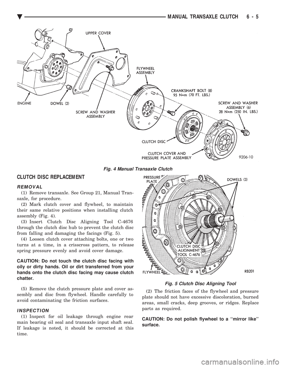
saxle, for procedure. (2) Mark clutch cover and flywheel, to maintain
their same relative positions when installing clutch
assembly (Fig. 4). (3) Insert Clutch Disc Aligning Tool C-4676
through the clutch disc hub to prevent the clutch disc
from falling and damaging the facings (Fig. 5). (4) Loosen clutch cover attaching bolts, one or two
turns at a time, in a crisscross pattern, to release
spring pressure evenly and avoid cover damage.
CAUTION: Do not touch the clutch disc facing with
oily or dirty hands. Oil or dirt transferred from your
hands onto the clutch disc facing may cause clutch
chatter.
(5) Remove the clutch pressure plate and cover as-
sembly and disc from flywheel. Handle carefully to
avoid contaminating the friction surfaces.
INSPECTION
(1) Inspect for oil leakage through engine rear
main bearing oil seal and transaxle input shaft seal.
If leakage is noted, it should be corrected at this
time. (2) The friction faces of the flywheel and pressure
plate should not have excessive discoloration, burned
areas, small cracks, deep grooves, or ridges. Replace
parts as required.
CAUTION: Do not polish flywheel to a ``mirror like''
surface.
Fig. 4 Manual Transaxle Clutch
Fig. 5 Clutch Disc Aligning Tool
Ä MANUAL TRANSAXLE CLUTCH 6 - 5
Page 338 of 2438
(3) Clean the flywheel face with medium sandpa-
per (80-160 grade), then wipe the surface with min-
eral spirits. If the surface is severely scored, heat
checked, or warped, replace the flywheel.
CAUTION: Do not flat-machine the flywheel face.
The surface profile is tapered.
(4) The heavy side of the flywheel is indicated by a
daub of white paint near the outside diameter. To
minimize the effects of flywheel unbalance, perform
the following installation procedure: (a) Loose assemble the flywheel to the crank-
shaft. Use new flywheel attaching bolts which have
sealant on the threads. If new bolts are not avail-
able, apply Loctite sealant to the threads of the
original bolts. This sealant is required to prevent
engine oil leakage. (b) Rotate the flywheel and crankshaft until the
daub of white paint (heavy side) is at the 12 o'clock
position. (c) Torque flywheel attaching bolts to 95 N Im(70
ft. lbs.). Use a crisscross pattern when tightening
bolts.
(5) The disc assembly should be handled without
touching the facings. Replace disc if the facings show
evidence of grease or oil soakage, or wear to within
less than .38 mm (.015 inch) of the rivet heads. The
splines on the disc hub and transaxle input shaft
should be a snug fit without signs of excessive wear.
Metallic portions of disc assembly should be dry and
clean, and not been discolored from excessive heat.
Each of the arched springs between the facings
should not be broken and all rivets should be tight. (6) Wipe the friction surface of the pressure plate
with mineral spirits. (7) Using a straight edge, check clutch cover (pres-
sure plate) for flatness. The clutch cover (pressure
plate) friction area should be slightly concave, with
the inner diameter 0.02 mm to 0.1 mm (.0008 in. to
.0039 in.) below the outer diameter. It should also be
free from discoloration, burned areas, cracks,
grooves, or ridges. (8) Using a surface plate, test cover for flatness.
All sections around attaching bolt holes should be in
contact with surface plate within .015 inch. (9) The cover should be a snug fit on flywheel dow-
els. If the clutch assembly does not meet these re-
quirements, it should be replaced.
INSTALLATION
(1) Mount clutch assembly on flywheel,being care-
ful to properly align dowels and the alignment marks
made before removal. The flywheel side of the clutch
disc is marked for proper installation. If new clutch
or flywheel is installed, align cover balance spot as
close as possible to flywheel balance orange spot. Ap-
ply pressure to the alignment tool. Center the tip of the tool into the crankshaft and the sliding cone into
the clutch fingers. Tighten the clutch attaching bolts
sufficiently to hold the disc in position. (2) To avoid distortion of the clutch cover, bolts
should be tightened a few turns at a time, in a criss-
cross pattern, until they are all seated. Tighten bolts
to 28 N Im (250 in. lbs.) following a crisscross pattern
sequence. Remove clutch disc alignment tool. (3) Install transaxle. See group 21, Manual Tran-
saxle, for procedures.
RELEASE BEARING AND FORK
Remove the transaxle from the vehicle. See group
21 for removal and installation procedures.
REMOVAL AND INSTALLATION
(1) Remove clutch release shaft E-clip.
(2) Remove the clutch release shaft and then slide
the fork and bearing assembly off the bearing pilot. (3) Remove the fork from the bearing thrust plate.
(4) Examine the condition of the bearing. It is pre-
lubricated and sealed and should not be im-
mersed in oil or solvent. (5) The bearing should turn smoothly when held in
the hand under a light thrust load. A light drag
caused by the lubricant fill is normal. If the bearing
is noisy, rough, or dry, replace the complete bearing
assembly with a new bearing. (6) The bearing has a plastic sleeve pre-lubricated
at assembly. Wipe out the old grease. Refill the
sleeve cavities and coat the inner surface with mul-
tipurpose grease. If the liner is cracked or worn, re-
place the bearing assembly. (7) Check the condition of the spring clips. If the
clips are broken or distorted, replace the bearing as-
sembly. (8) Before assembling the fork, lubricate the
rounded thrust pads and the spring clip cavities with
multipurpose grease. (9) Assemble the fork to the bearing by sliding the
thrust pads under the spring clips. Be careful to
avoid distorting the spring clips. These clips prevent
the bearing thrust plate from rotating with the bear-
ing. (10) Slide the bearing and fork assembly onto the
input shaft bearing retainer. (11) Position the release shaft bushings in the
housing and install the release shaft. A small
amount of bearing grease between the release shaft
bushing and the shaft is beneficial but not required.
Install the retainer clip in the shaft groove near the
large bushing. (12) Install the release lever and retaining clip on
the outer end of the release shaft.
CLEANING PRECAUTIONS
Condensation from steam vapors tend to accumu-
late on the internal clutch mechanism when the ve-
6 - 6 MANUAL TRANSAXLE CLUTCH Ä
Page 343 of 2438
COOLING SYSTEM
CONTENTS
page page
ACCESSORY DRIVE BELTS ............... 24
ENGINE BLOCK HEATER ................. 28
GENERAL INFORMATION .................. 1 SERVICE PROCEDURES
.................. 10
SPECIFICATIONS ....................... 29
GENERAL INFORMATION
Throughout this group, references may be made to
a particular vehicle by letter or number designation.
A chart showing the breakdown of these designations
is included in the Introduction Section at the front of
this service manual.
COOLING SYSTEM
The cooling system consists of an engine cooling
module, thermostat, coolant, a water pump to circu-
late the coolant. The engine cooling module may con-
sist of a radiator, electric fan motor, shroud, radiator
pressure cap, coolant reserve system, transmission oil
cooler, hoses, clamps, air condition condenser, trans-
mission oil lines and charge air cooler.
² When Engine is cold: Thermostat is closed, cooling
system has no flow through the radiator. The coolant
bypass flows through the engine only. ²
When Engine is warm: Thermostat is open, cooling
system has bypass flow and coolant flow through ra-
diator. Its primary purpose is to maintain engine temper-
ature in a range that will provide satisfactory engine
performance and emission levels under all expected
driving conditions. It also provides hot water (cool-
ant) for heater performance and cooling for auto-
matic transmission oil. It does this by transferring
heat from engine metal to coolant, moving this
heated coolant to the radiator, and then transferring
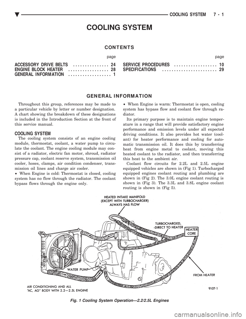
this heat to the ambient air. Coolant flow circuits for 2.2L and 2.5L engine
equipped vehicles are shown in (Fig 1). Turbocharged
equipped engines coolant routing and plumbing are
shown in (Fig 2). The 3.0L engine coolant routing is
shown in (Fig 3). The 3.3L and 3.8L engine coolant
routing is shown in (Fig 5).
Fig. 1 Cooling System OperationÐ2.2/2.5L Engines
Ä COOLING SYSTEM 7 - 1
Page 352 of 2438
SERVICE PROCEDURES INDEX
page page
Automatic Transmission Oil Coolers .......... 23
Coolant ................................ 14
Coolant Recovery System (CRS) ............. 17
Cooling System Drain, Clean, Flush and Refill . . 15
Electric Fan Motor ........................ 22
Engine Thermostats ....................... 13
Fan Shroud ............................. 23 Fans
.................................. 21
Radiator Hoses .......................... 21
Radiator Pressure Cap .................... 18
Radiators ............................... 18
Testing System for Leaks .................. 17
Water Pumps ........................... 10
WATER PUMPS
A quick test to tell whether or not the pump is
working is to see if the heater warms properly. A
defective pump will not be able to circulate heated
coolant through the long heater hose. The water pump on all models can be replaced
without discharging the air conditioning system.
WATER PUMPÐ2.2/2.5L ENGINE
The 2.2/2.5L engine water pump has a diecast alu-
minum body and housing with a stamped steel impel-
ler. The 2.2/2.5L pump uses an O-ring gasket between
body and housing. The assembly bolts directly to the
block. Cylinder block to water pump sealing is provided
by a rubber O-ring.
REMOVAL (1) Drain cooling system. Refer to Draining Cooling
System in this group. (2) If equipped with air conditioning, see Solid
Mount Accessory Bracket in (Standard Service Proce-
dures) Group 9, Engine: (a) Remove air conditioning compressor and gen-
erator from solid mount bracket and set aside.It is
not necessary to discharge the a/c system. (b) Remove solid mount bracket.
(3) If the vehicle is not equipped with air condi-
tioning, remove generator and mounting bracket. (4) Disconnect lower radiator and heater hoses
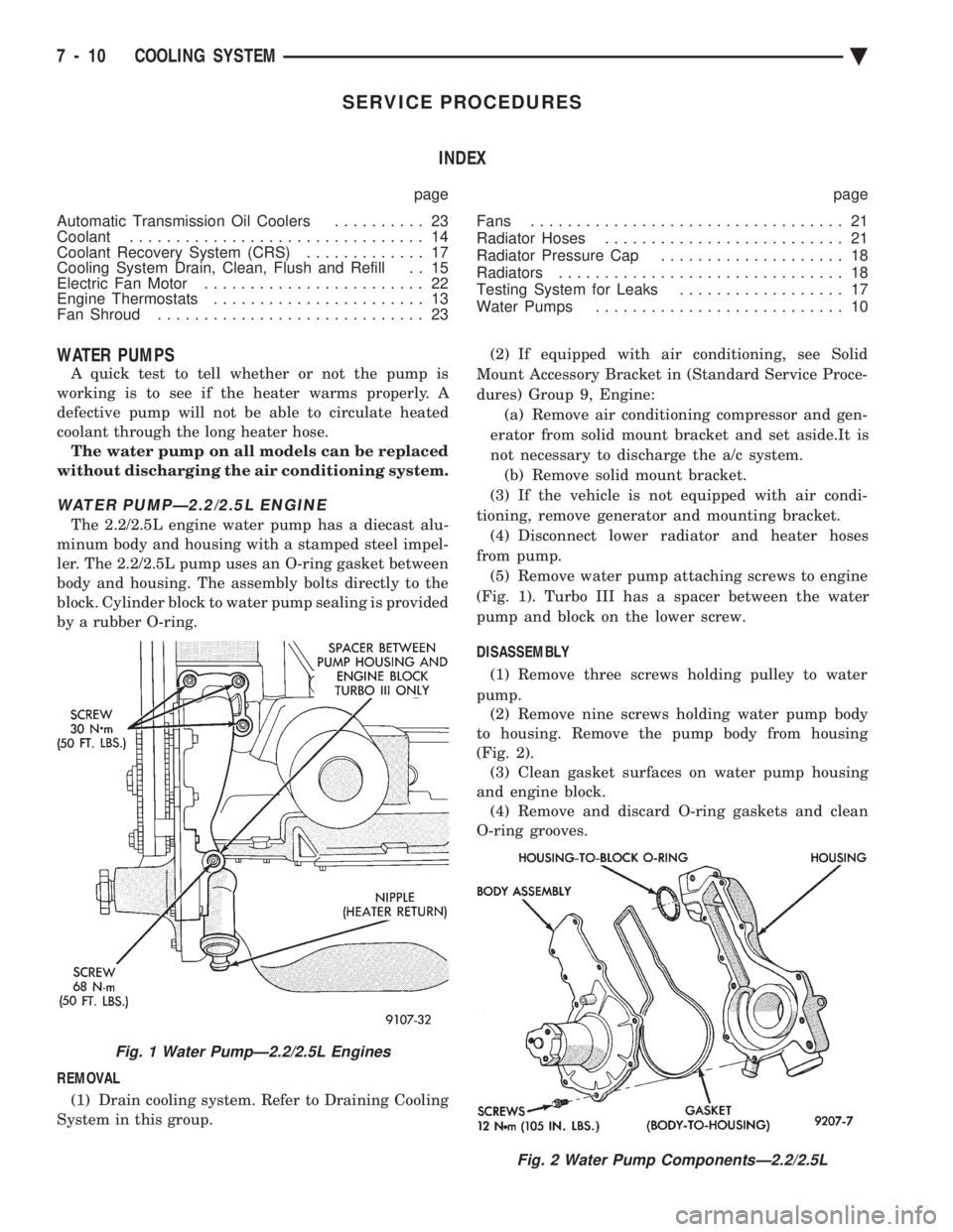
from pump. (5) Remove water pump attaching screws to engine
(Fig. 1). Turbo III has a spacer between the water
pump and block on the lower screw.
DISASSEMBLY (1) Remove three screws holding pulley to water
pump. (2) Remove nine screws holding water pump body
to housing. Remove the pump body from housing
(Fig. 2). (3) Clean gasket surfaces on water pump housing
and engine block. (4) Remove and discard O-ring gaskets and clean
O-ring grooves.
Fig. 2 Water Pump ComponentsÐ2.2/2.5L
Fig. 1 Water PumpÐ2.2/2.5L Engines
7 - 10 COOLING SYSTEM Ä
Page 354 of 2438
(1) Damage or cracks on the pump body.
(2) Coolant leaks, if the shaft seal is leaking, evi-
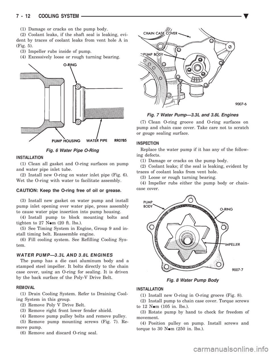
dent by traces of coolant leaks from vent hole A in
(Fig. 5). (3) Impeller rubs inside of pump.
(4) Excessively loose or rough turning bearing.
INSTALLATION (1) Clean all gasket and O-ring surfaces on pump
and water pipe inlet tube. (2) Install new O-ring on water inlet pipe (Fig. 6).
Wet the O-ring with water to facilitate assembly.
CAUTION: Keep the O-ring free of oil or grease.
(3) Install new gasket on water pump and install
pump inlet opening over water pipe, press assembly
to cause water pipe insertion into pump housing. (4) Install pump to block mounting bolts and
tighten to 27 N Im (20 ft. lbs.).
(5) See Timing System in Engine, Group 9 and in-
stall timing belt. Reassemble engine. (6) Fill cooling system. See Refilling Cooling Sys-
tem.
WATER PUMPÐ3.3L AND 3.8L ENGINES
The pump has a die cast aluminum body and a
stamped steel impeller. It bolts directly to the chain
case cover, using an O-ring for sealing. It is driven
by the back surface of the Poly-V Drive Belt.
REMOVAL (1) Drain Cooling System. Refer to Draining Cool-
ing System in this group. (2) Remove Poly V Drive Belt.
(3) Remove right front lower fender shield.
(4) Remove pump pulley bolts and remove pulley.
(5) Remove pump mounting screws (Fig. 7). Re-
move pump. (6) Remove and discard O-ring seal. (7) Clean O-ring groove and O-ring surfaces on
pump and chain case cover. Take care not to scratch
or gouge sealing surface.
INSPECTION
Replace the water pump if it has any of the follow-
ing defects. (1) Damage or cracks on the pump body.
(2) Coolant leaks; if the seal is leaking, evident by
traces of coolant leaks from vent hole. (3) Loose or rough turning bearing.
(4) Impeller rubs either the pump body or chain-
case cover.
INSTALLATION
(1) Install new O-ring in O-ring groove (Fig. 8).
(2) Install pump to chain case cover. Torque screws
to 12 N Im (105 in. lbs.).
(3) Rotate pump by hand to check for freedom of
movement. (4) Position pulley on pump. Install screws and
torque to 30 N Im (250 in. lbs.).
Fig. 6 Water Pipe O-Ring
Fig. 7 Water PumpÐ3.3L and 3.8L Engines
Fig. 8 Water Pump Body
7 - 12 COOLING SYSTEM Ä