1993 CHEVROLET DYNASTY compression ratio
[x] Cancel search: compression ratioPage 1893 of 2438

the PCM determines crankshaft position, it begins
energizing the injectors in sequence.The auto shutdown (ASD) relay supplies battery
voltage to the injectors. The PCM provides the
ground path for the injectors. By switching the
ground path on and off, the PCM adjusts injector
pulse width. Pulse width is the amount of time the
injector is energized. The PCM adjusts injector pulse
width based on inputs it receives.
IGNITION COILÐPCM OUTPUT
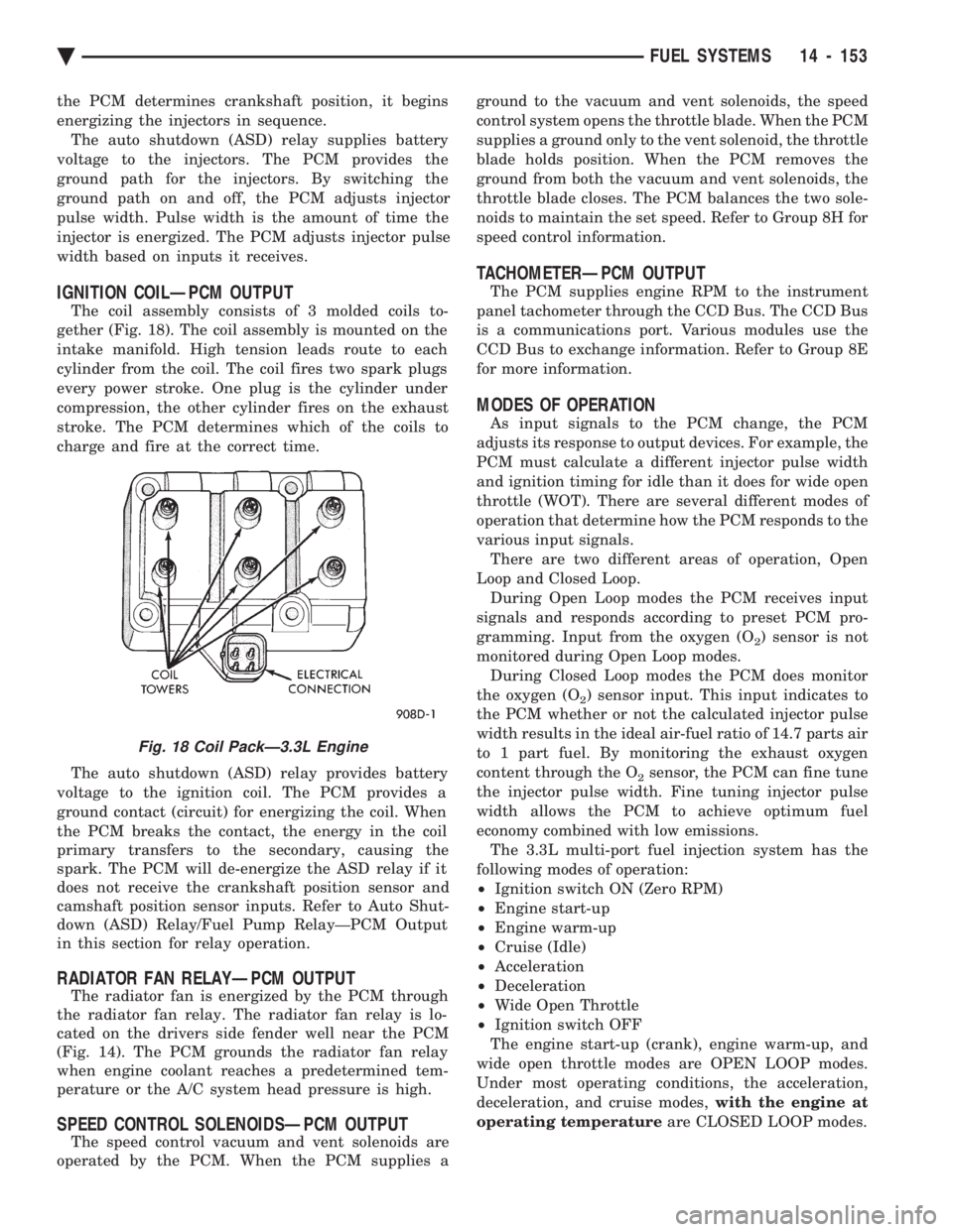
The coil assembly consists of 3 molded coils to-
gether (Fig. 18). The coil assembly is mounted on the
intake manifold. High tension leads route to each
cylinder from the coil. The coil fires two spark plugs
every power stroke. One plug is the cylinder under
compression, the other cylinder fires on the exhaust
stroke. The PCM determines which of the coils to
charge and fire at the correct time.
The auto shutdown (ASD) relay provides battery
voltage to the ignition coil. The PCM provides a
ground contact (circuit) for energizing the coil. When
the PCM breaks the contact, the energy in the coil
primary transfers to the secondary, causing the
spark. The PCM will de-energize the ASD relay if it
does not receive the crankshaft position sensor and
camshaft position sensor inputs. Refer to Auto Shut-
down (ASD) Relay/Fuel Pump RelayÐPCM Output
in this section for relay operation.
RADIATOR FAN RELAYÐPCM OUTPUT
The radiator fan is energized by the PCM through
the radiator fan relay. The radiator fan relay is lo-
cated on the drivers side fender well near the PCM
(Fig. 14). The PCM grounds the radiator fan relay
when engine coolant reaches a predetermined tem-
perature or the A/C system head pressure is high.
SPEED CONTROL SOLENOIDSÐPCM OUTPUT
The speed control vacuum and vent solenoids are
operated by the PCM. When the PCM supplies a ground to the vacuum and vent solenoids, the speed
control system opens the throttle blade. When the PCM
supplies a ground only to the vent solenoid, the throttle
blade holds position. When the PCM removes the
ground from both the vacuum and vent solenoids, the
throttle blade closes. The PCM balances the two sole-
noids to maintain the set speed. Refer to Group 8H for
speed control information.
TACHOMETERÐPCM OUTPUT
The PCM supplies engine RPM to the instrument
panel tachometer through the CCD Bus. The CCD Bus
is a communications port. Various modules use the
CCD Bus to exchange information. Refer to Group 8E
for more information.
MODES OF OPERATION
As input signals to the PCM change, the PCM
adjusts its response to output devices. For example, the
PCM must calculate a different injector pulse width
and ignition timing for idle than it does for wide open
throttle (WOT). There are several different modes of
operation that determine how the PCM responds to the
various input signals. There are two different areas of operation, Open
Loop and Closed Loop. During Open Loop modes the PCM receives input
signals and responds according to preset PCM pro-
gramming. Input from the oxygen (O
2) sensor is not
monitored during Open Loop modes. During Closed Loop modes the PCM does monitor
the oxygen (O
2) sensor input. This input indicates to
the PCM whether or not the calculated injector pulse
width results in the ideal air-fuel ratio of 14.7 parts air
to 1 part fuel. By monitoring the exhaust oxygen
content through the O
2sensor, the PCM can fine tune
the injector pulse width. Fine tuning injector pulse
width allows the PCM to achieve optimum fuel
economy combined with low emissions. The 3.3L multi-port fuel injection system has the
following modes of operation:
² Ignition switch ON (Zero RPM)
² Engine start-up
² Engine warm-up
² Cruise (Idle)
² Acceleration
² Deceleration
² Wide Open Throttle
² Ignition switch OFF
The engine start-up (crank), engine warm-up, and
wide open throttle modes are OPEN LOOP modes.
Under most operating conditions, the acceleration,
deceleration, and cruise modes, with the engine at
operating temperature are CLOSED LOOP modes.
Fig. 18 Coil PackÐ3.3L Engine
Ä FUEL SYSTEMS 14 - 153
Page 2248 of 2438

ADJUSTMENT PROCEDURES
DOWEL PIN ADJUSTMENTS (FIG. 9)
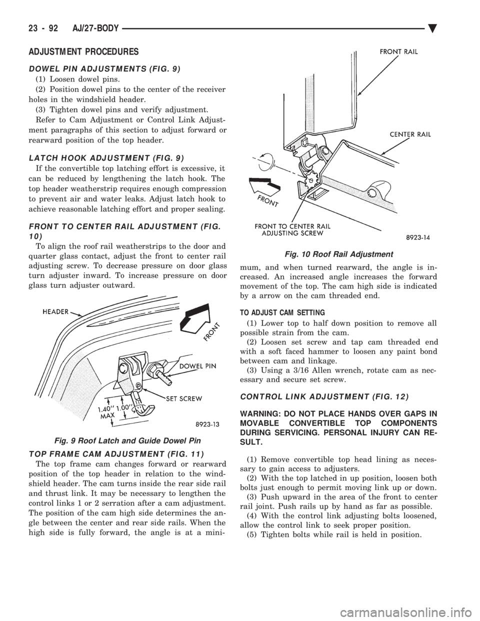
(1) Loosen dowel pins.
(2) Position dowel pins to the center of the receiver
holes in the windshield header. (3) Tighten dowel pins and verify adjustment.
Refer to Cam Adjustment or Control Link Adjust-
ment paragraphs of this section to adjust forward or
rearward position of the top header.
LATCH HOOK ADJUSTMENT (FIG. 9)
If the convertible top latching effort is excessive, it
can be reduced by lengthening the latch hook. The
top header weatherstrip requires enough compression
to prevent air and water leaks. Adjust latch hook to
achieve reasonable latching effort and proper sealing.
FRONT TO CENTER RAIL ADJUSTMENT (FIG. 10)
To align the roof rail weatherstrips to the door and
quarter glass contact, adjust the front to center rail
adjusting screw. To decrease pressure on door glass
turn adjuster inward. To increase pressure on door
glass turn adjuster outward.
TOP FRAME CAM ADJUSTMENT (FIG. 11)
The top frame cam changes forward or rearward
position of the top header in relation to the wind-
shield header. The cam turns inside the rear side rail
and thrust link. It may be necessary to lengthen the
control links 1 or 2 serration after a cam adjustment.
The position of the cam high side determines the an-
gle between the center and rear side rails. When the
high side is fully forward, the angle is at a mini- mum, and when turned rearward, the angle is in-
creased. An increased angle increases the forward
movement of the top. The cam high side is indicated
by a arrow on the cam threaded end.
TO ADJUST CAM SETTING (1) Lower top to half down position to remove all
possible strain from the cam. (2) Loosen set screw and tap cam threaded end
with a soft faced hammer to loosen any paint bond
between cam and linkage. (3) Using a 3/16 Allen wrench, rotate cam as nec-
essary and secure set screw.
CONTROL LINK ADJUSTMENT (FIG. 12)
WARNING: DO NOT PLACE HANDS OVER GAPS IN
MOVABLE CONVERTIBLE TOP COMPONENTS
DURING SERVICING. PERSONAL INJURY CAN RE-
SULT.
(1) Remove convertible top head lining as neces-
sary to gain access to adjusters. (2) With the top latched in up position, loosen both
bolts just enough to permit moving link up or down. (3) Push upward in the area of the front to center
rail joint. Push rails up by hand as far as possible. (4) With the control link adjusting bolts loosened,
allow the control link to seek proper position. (5) Tighten bolts while rail is held in position.
Fig. 9 Roof Latch and Guide Dowel Pin
Fig. 10 Roof Rail Adjustment
23 - 92 AJ/27-BODY Ä
Page 2287 of 2438

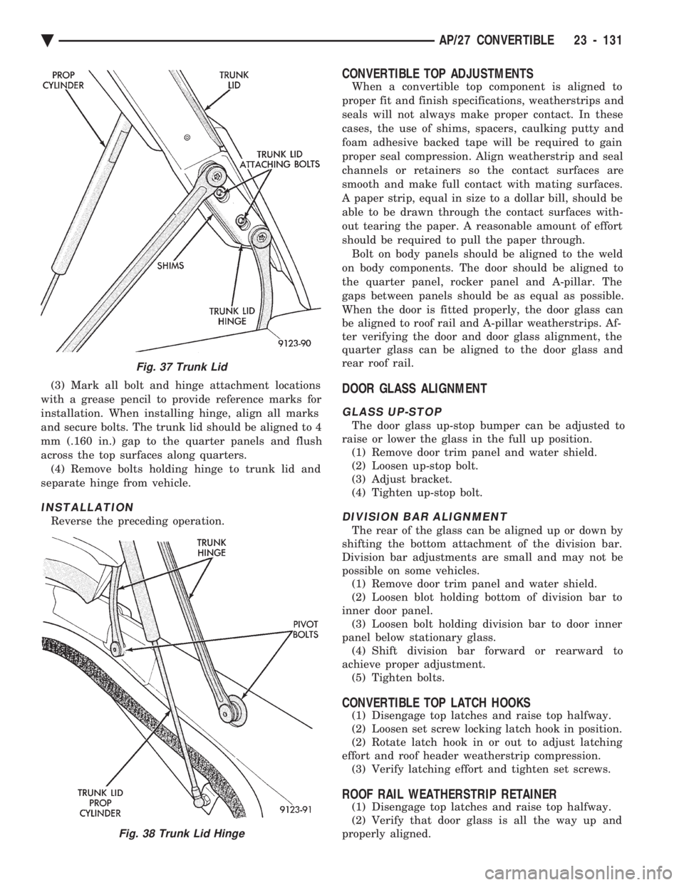
(3) Mark all bolt and hinge attachment locations
with a grease pencil to provide reference marks for
installation. When installing hinge, align all marks
and secure bolts. The trunk lid should be aligned to 4
mm (.160 in.) gap to the quarter panels and flush
across the top surfaces along quarters. (4) Remove bolts holding hinge to trunk lid and
separate hinge from vehicle.
INSTALLATION
Reverse the preceding operation.
CONVERTIBLE TOP ADJUSTMENTS
When a convertible top component is aligned to
proper fit and finish specifications, weatherstrips and
seals will not always make proper contact. In these
cases, the use of shims, spacers, caulking putty and
foam adhesive backed tape will be required to gain
proper seal compression. Align weatherstrip and seal
channels or retainers so the contact surfaces are
smooth and make full contact with mating surfaces.
A paper strip, equal in size to a dollar bill, should be
able to be drawn through the contact surfaces with-
out tearing the paper. A reasonable amount of effort
should be required to pull the paper through. Bolt on body panels should be aligned to the weld
on body components. The door should be aligned to
the quarter panel, rocker panel and A-pillar. The
gaps between panels should be as equal as possible.
When the door is fitted properly, the door glass can
be aligned to roof rail and A-pillar weatherstrips. Af-
ter verifying the door and door glass alignment, the
quarter glass can be aligned to the door glass and
rear roof rail.
DOOR GLASS ALIGNMENT
GLASS UP-STOP
The door glass up-stop bumper can be adjusted to
raise or lower the glass in the full up position. (1) Remove door trim panel and water shield.
(2) Loosen up-stop bolt.
(3) Adjust bracket.
(4) Tighten up-stop bolt.
DIVISION BAR ALIGNMENT
The rear of the glass can be aligned up or down by
shifting the bottom attachment of the division bar.
Division bar adjustments are small and may not be
possible on some vehicles. (1) Remove door trim panel and water shield.
(2) Loosen blot holding bottom of division bar to
inner door panel. (3) Loosen bolt holding division bar to door inner
panel below stationary glass. (4) Shift division bar forward or rearward to
achieve proper adjustment. (5) Tighten bolts.
CONVERTIBLE TOP LATCH HOOKS
(1) Disengage top latches and raise top halfway.
(2) Loosen set screw locking latch hook in position.
(2) Rotate latch hook in or out to adjust latching
effort and roof header weatherstrip compression. (3) Verify latching effort and tighten set screws.
ROOF RAIL WEATHERSTRIP RETAINER
(1) Disengage top latches and raise top halfway.
(2) Verify that door glass is all the way up and
properly aligned.
Fig. 37 Trunk Lid
Fig. 38 Trunk Lid Hinge
Ä AP/27 CONVERTIBLE 23 - 131
Page 2288 of 2438

(3) Loosen nuts holding roof rail weatherstrip re-
tainer to roof rail. Shift retainer inboard or outboard
to achieve proper alignment. (4) Tighten nuts to hold retainer to roof rail and
latch top header. (5) Verify weatherstrip sealing and door closing ef-
fort.
QUARTER GLASS AND ROLLER BRACKET
QUARTER GLASS
(1) Verify that door glass is properly aligned.
(2) Loosen nut holding top of quarter glass to rear
roof rail. (3) Shift quarter glass inboard or outboard, for-
ward or rearward to achieve proper alignment. (4) Tighten nut to hold top of quarter glass to rear
roof rail. (5) Verify door glass operation and weatherstrip
sealing.
ROLLER BRACKET
The roller bracket controls the in and out move-
ment at the bottom for the quarter glass. (1) Remove quarter trim panel as necessary to
gain access to the bottom of the quarter glass. (2) Lower convertible top.
(3) Loosen bolts holding roller bracket to quarter
panel reinforcement. (4) Align roller bracket to reduce quarter belt
weatherstrip contact when top is raised and proper
sash weatherstrip compression against the door
glass. (5) Tighten bolts to hold roller to quarter panel
and verify top operation and weatherstrip sealing.
TOP STACK DOWN-STOP
Adjust down-stop in or out to set top stack down
position height.
CAUTION: Avoid setting top stack position too low,
top cover can be pinched and cut between wheel-
house and fourth bow. Seal base of down-stop with silicone after adjust-
ing to prevent water leaks.
TOP STACK UP-STOP
Adjust up-stop in or out to change the contact with
the rear rail. This will effect the fore/aft position of
the No. 1 bow.
FOURTH ROOF BOW SLAT
Adjust the fourth roof bow slat to reduce wrinkles
and bagging around rear window and sail panels. (1) Verify convertible top is up and latched.
(2) Loosen bolts holding the slat to the fourth roof
bow. (3) Slide the bow up or down as necessary and
tighten bolts.
REAR TENSIONER PLATE
Adjust rear tensioner plate by loosening screws, po-
sitioning plate forward or backward, and tightening
screws. Tension can be adjusted on the back of the
top cover by varying contact.
23 - 132 AP/27 CONVERTIBLE Ä