1993 CHEVROLET DYNASTY brakes
[x] Cancel search: brakesPage 227 of 2438
circuits are hydraulically isolated so a leak or mal-
function in one circuit will allow continued braking
ability in the other.When force is applied to the brake pedal, the input
pushrod applies force to the boost control valve. As
the boost control valve is moved, it allows the pres-
surized fluid from the accumulator to flow into the
master cylinder booster chamber. The pressure gen-
erated in the booster chamber is directly propor-
tioned to the brake pedal force exerted by the driver.
This pressure in the booster servo in turn applies
pressure to the primary master cylinder piston that
in turn applies pressure to the secondary master cyl-
inder piston. The pressure generated in the primary
and secondary circuits are used to apply the brakes
during normal braking.
WARNING: THE HYDRAULIC ACCUMULATORS
CONTAIN BRAKE FLUID AND NITROGEN GAS AT
HIGH PRESSURE. CERTAIN PORTIONS OF THE
BRAKE SYSTEM ALSO CONTAIN BRAKE FLUID AT
HIGH PRESSURE. REMOVAL OR DISASSEMBLY
MAY RESULT IN PERSONAL INJURY AND IM-
PROPER SYSTEM OPERATION. REFER TO THE AP-
PROPRIATE SERVICE MANUAL FOR PROPER
SERVICE PROCEDURES.
HYDRAULIC BLADDER ACCUMULATOR
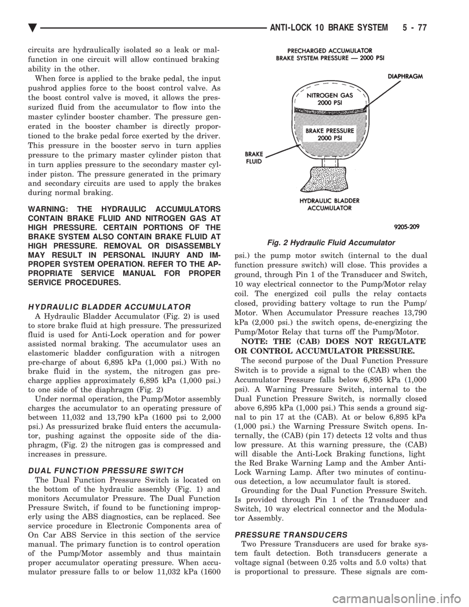
A Hydraulic Bladder Accumulator (Fig. 2) is used
to store brake fluid at high pressure. The pressurized
fluid is used for Anti-Lock operation and for power
assisted normal braking. The accumulator uses an
elastomeric bladder configuration with a nitrogen
pre-charge of about 6,895 kPa (1,000 psi.) With no
brake fluid in the system, the nitrogen gas pre-
charge applies approximately 6,895 kPa (1,000 psi.)
to one side of the diaphragm (Fig. 2) Under normal operation, the Pump/Motor assembly
charges the accumulator to an operating pressure of
between 11,032 and 13,790 kPa (1600 psi to 2,000
psi.) As pressurized brake fluid enters the accumula-
tor, pushing against the opposite side of the dia-
phragm, (Fig. 2) the nitrogen gas is compressed and
increases in pressure.
DUAL FUNCTION PRESSURE SWITCH
The Dual Function Pressure Switch is located on
the bottom of the hydraulic assembly (Fig. 1) and
monitors Accumulator Pressure. The Dual Function
Pressure Switch, if found to be functioning improp-
erly using the ABS diagnostics, can be replaced. See
service procedure in Electronic Components area of
On Car ABS Service in this section of the service
manual. The primary function is to control operation
of the Pump/Motor assembly and thus maintain
proper accumulator operating pressure. When accu-
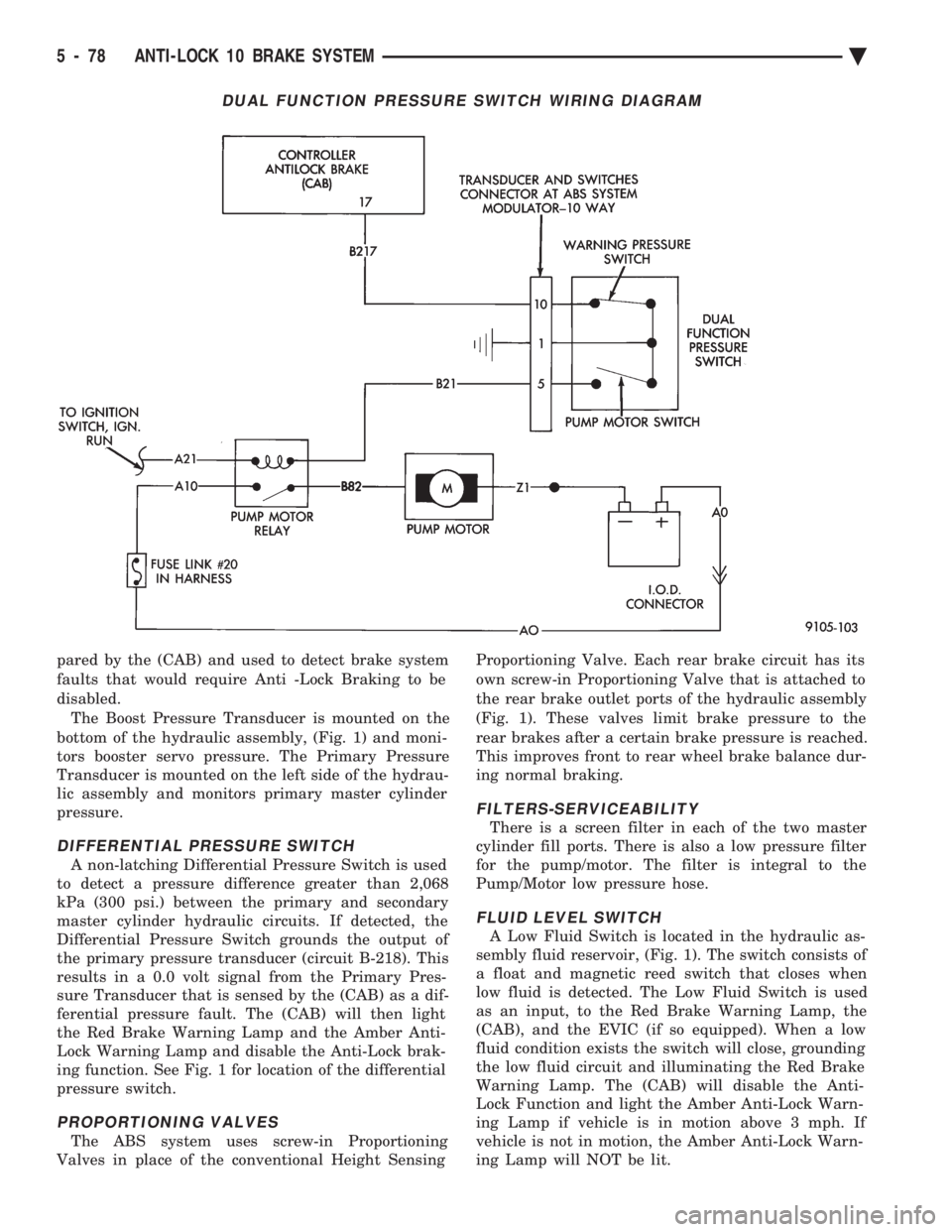
mulator pressure falls to or below 11,032 kPa (1600 psi.) the pump motor switch (internal to the dual
function pressure switch) will close. This provides a
ground, through Pin 1 of the Transducer and Switch,
10 way electrical connector to the Pump/Motor relay
coil. The energized coil pulls the relay contacts
closed, providing battery voltage to run the Pump/
Motor. When Accumulator Pressure reaches 13,790
kPa (2,000 psi.) the switch opens, de-energizing the
Pump/Motor Relay that turns off the Pump/Motor. NOTE: THE (CAB) DOES NOT REGULATE
OR CONTROL ACCUMULATOR PRESSURE. The second purpose of the Dual Function Pressure
Switch is to provide a signal to the (CAB) when the
Accumulator Pressure falls below 6,895 kPa (1,000
psi). A Warning Pressure Switch, internal to the
Dual Function Pressure Switch, is normally closed
above 6,895 kPa (1,000 psi.) This sends a ground sig-
nal to pin 17 at the (CAB). At or below 6,895 kPa
(1,000 psi.) the Warning Pressure Switch opens. In-
ternally, the (CAB) (pin 17) detects 12 volts and thus
low pressure. At this warning pressure, the (CAB)
will disable the Anti-Lock Braking functions, light
the Red Brake Warning Lamp and the Amber Anti-
Lock Warning Lamp. After two minutes of continu-
ous detection, a low accumulator fault is stored. Grounding for the Dual Function Pressure Switch.
Is provided through Pin 1 of the Transducer and
Switch, 10 way electrical connector and the Modula-
tor Assembly.
PRESSURE TRANSDUCERS
Two Pressure Transducers are used for brake sys-
tem fault detection. Both transducers generate a
voltage signal (between 0.25 volts and 5.0 volts) that
is proportional to pressure. These signals are com-
Fig. 2 Hydraulic Fluid Accumulator
Ä ANTI-LOCK 10 BRAKE SYSTEM 5 - 77
Page 228 of 2438
pared by the (CAB) and used to detect brake system
faults that would require Anti -Lock Braking to be
disabled.The Boost Pressure Transducer is mounted on the
bottom of the hydraulic assembly, (Fig. 1) and moni-
tors booster servo pressure. The Primary Pressure
Transducer is mounted on the left side of the hydrau-
lic assembly and monitors primary master cylinder
pressure.
DIFFERENTIAL PRESSURE SWITCH
A non-latching Differential Pressure Switch is used
to detect a pressure difference greater than 2,068
kPa (300 psi.) between the primary and secondary
master cylinder hydraulic circuits. If detected, the
Differential Pressure Switch grounds the output of
the primary pressure transducer (circuit B-218). This
results in a 0.0 volt signal from the Primary Pres-
sure Transducer that is sensed by the (CAB) as a dif-
ferential pressure fault. The (CAB) will then light
the Red Brake Warning Lamp and the Amber Anti-
Lock Warning Lamp and disable the Anti-Lock brak-
ing function. See Fig. 1 for location of the differential
pressure switch.
PROPORTIONING VALVES
The ABS system uses screw-in Proportioning
Valves in place of the conventional Height Sensing Proportioning Valve. Each rear brake circuit has its
own screw-in Proportioning Valve that is attached to
the rear brake outlet ports of the hydraulic assembly
(Fig. 1). These valves limit brake pressure to the
rear brakes after a certain brake pressure is reached.
This improves front to rear wheel brake balance dur-
ing normal braking.
FILTERS-SERVICEABILITY
There is a screen filter in each of the two master
cylinder fill ports. There is also a low pressure filter
for the pump/motor. The filter is integral to the
Pump/Motor low pressure hose.
FLUID LEVEL SWITCH
A Low Fluid Switch is located in the hydraulic as-
sembly fluid reservoir, (Fig. 1). The switch consists of
a float and magnetic reed switch that closes when
low fluid is detected. The Low Fluid Switch is used
as an input, to the Red Brake Warning Lamp, the
(CAB), and the EVIC (if so equipped). When a low
fluid condition exists the switch will close, grounding
the low fluid circuit and illuminating the Red Brake
Warning Lamp. The (CAB) will disable the Anti-
Lock Function and light the Amber Anti-Lock Warn-
ing Lamp if vehicle is in motion above 3 mph. If
vehicle is not in motion, the Amber Anti-Lock Warn-
ing Lamp will NOT be lit.
DUAL FUNCTION PRESSURE SWITCH WIRING DIAGRAM
5 - 78 ANTI-LOCK 10 BRAKE SYSTEM Ä
Page 232 of 2438

The primary functions of the (CAB) are:
² (1) Detect wheel locking tendencies.
² (2) Control fluid modulation to the brakes while in
Anti-Lock mode.
² (3) Monitor the system for proper operation.
² (4) Provide communication to the DRB II while in
diagnostic mode. The (CAB) continuously monitors the speed of each
wheel, through the signals generated at the Wheel
Speed Sensors, to determine if any wheel is begin-
ning to lock. When a wheel locking tendency is de-
tected, the (CAB) will isolate the master cylinder
from the wheel brakes. This is done by activating the
Isolation Valves. The (CAB) then commands the ap-
propriate Build or Decay valves to modulate brake
fluid pressure in some or all of the hydraulic circuits.
The fluid used for modulation comes from the booster
servo circuit. The (CAB) continues to control pres-
sure in individual hydraulic circuits until a locking
tendency is no longer present. The (ABS) system is constantly monitored by the
(CAB) for proper operation. If the (CAB) detects a
fault, it can disable the Anti-Lock braking function.
Depending on the fault, the (CAB) will light one or
both of the brake warning lamps. The (CAB) contains a System Diagnostic Program
which triggers the brake system warning lamps
when a system fault is detected. Faults are stored in
a diagnostic program memory. There are 19 fault
codes that may be stored in the (CAB) and displayed
through the DRB II. These fault codes will remain in
the (CAB) memory even after the ignition has been
turned off. These fault codes will remain in memory
until they are cleared with the DRB II, or automati-
cally erased from the memory after (50) ignition
switch on/off cycles.
CONTROLLER ANTI-LOCK BRAKE (INPUTS)
² Four wheel speed sensors.
² Boost pressure transducer.
² Primary pressure transducer.
² Low fluid level switch.
² Differential pressure switch.
² Parking brake switch.
² Dual function pressure switch (warning pressure
only)
² Stop lamp switch.
² Ignition switch.
² System relay voltage.
² Ground.
² Low Accumulator
CONTROLLER ANTI-LOCK BRAKE (OUTPUTS)
²Ten modulator valves-3 decay, 3 build and 4 isola-
tion.
² Red Brake warning lamp.
² Amber Anti-Lock Warning Lamp.
² System relay actuation. ²
Diagnostic communication.
ABS SYSTEM DIAGNOSTIC CONNECTOR
The Bendix Anti-Lock system diagnostic connector
is located under the lower dash panel or in the area
of the fuse box (Fig. 8). The fuse box is located be-
hind the access panel that is on the bottom portion of
the dash panel, left of the steering column. The diag-
nostics connector is a blue 6 way connector.
ANTI-LOCK SYSTEM RELAYS AND WARNING
LAMPS
PUMP/MOTOR RELAY
Pump/Motor power is supplied by the Pump/Motor
Relay. The Pump/Motor relay is located inside the
Power Distribution Center (PDC). The relay coil is
energized by a ground from the Dual Function Pres-
sure Switch. See (Fig. 9) for the location of the pump/
motor relay in the (PDC).
SYSTEM RELAY
The (ABS) Modulator Valves and Anti-Lock Warn-
ing Lamp Relay are controlled through a System Re-
lay. The System relay is located on the top left inner
fender behind the headlight (Fig. 10). The system re-
lay provides power to the (CAB) for modulator valve
operation (pins 47 and 50) after the start-up cycle
when the ignition is turned on.
ANTI-LOCK WARNING LAMP RELAY
The Anti-Lock Warning Lamp is controlled by the
Yellow Light Relay. See (Fig. 10) for location behind
the left headlight. With the relay de-energized, the
lamp is lit. When the system relay is energized by
Fig. 8 A.B.S. Diagnostic Connector Location
5 - 82 ANTI-LOCK 10 BRAKE SYSTEM Ä
Page 235 of 2438
ABS HYDRAULIC CIRCUITS AND VALVE
OPERATION
Through the following operation descriptions and
diagrams. The function of the various hydraulic con-
trol valves in the ABS system will be described. The
fluid control valves mentioned below, control the flow
of pressurized brake fluid to the wheel brakes during
the different modes of Anti-Lock Braking.
NORMAL BRAKING
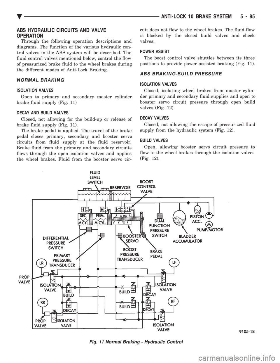
ISOLATION VALVES
Open to primary and secondary master cylinder
brake fluid supply (Fig. 11)
DECAY AND BUILD VALVES
Closed, not allowing for the build-up or release of
brake fluid supply (Fig. 11). The brake pedal is applied. The travel of the brake
pedal closes primary, secondary and booster servo
circuits from fluid supply at the fluid reservoir.
Brake fluid from the primary and secondary circuits
flows through the open isolation valves and applies
the wheel brakes. Fluid from the booster servo cir- cuit does not flow to the wheel brakes. The fluid flow
is blocked by the closed build valves and check
valves.
POWER ASSIST
The boost control valve shuttles between its three
positions to provide power assisted braking (Fig. 11).
ABS BRAKING-BUILD PRESSURE
ISOLATION VALVES
Closed, isolating wheel brakes from master cylin-
der primary and secondary fluid supplies and open to
booster servo circuit pressure through open build
valves (Fig. 12)
DECAY VALVES
Closed, not allowing the escape of pressurized fluid
supply from the hydraulic system (Fig. 12).
BUILD VALVES
Open, allowing booster servo circuit pressure to
flow to the wheel brakes through the isolation valves
(Fig. 12).
Fig. 11 Normal Braking - Hydraulic Control
Ä ANTI-LOCK 10 BRAKE SYSTEM 5 - 85
Page 236 of 2438

POWER ASSIST The boost control valve shuttles between its three
positions to provide power assisted braking (Fig. 12).
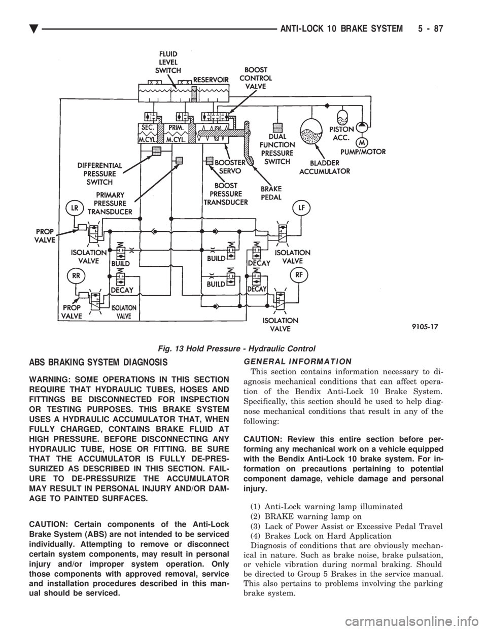
ABS BRAKING-HOLD PRESSURE
For explanation purposes we will assume all speed
sensors are sending the same wheel speed informa-
tion, requiring the same modulation at the same
rate.
ISOLATION VALVES Closed, isolating the wheel brakes from the master
cylinder primary and secondary fluid supplies. Build
and decay valves are closed preventing any fluid
from reaching the open isolation valves (Fig. 13).
DECAY AND BUILD VALVES Closed, not allowing fluid supply to reach the open
isolation valves (Fig. 13).
ABS BRAKING-DECAY PRESSURE
ISOLATION VALVES
Closed, isolating the wheel brakes from the master
cylinder primary and secondary fluid supplies (Fig.
14)
DECAY VALVES Open, allowing release of fluid pressure through
decay valve to the fluid reservoir (Fig. 14)
BUILD VALVE Closed, blocking booster servo circuit fluid to wheel
brakes (Fig. 14).
Fig. 12 Build Pressure - Hydraulic Control
5 - 86 ANTI-LOCK 10 BRAKE SYSTEM Ä
Page 237 of 2438
ABS BRAKING SYSTEM DIAGNOSIS
WARNING: SOME OPERATIONS IN THIS SECTION
REQUIRE THAT HYDRAULIC TUBES, HOSES AND
FITTINGS BE DISCONNECTED FOR INSPECTION
OR TESTING PURPOSES. THIS BRAKE SYSTEM
USES A HYDRAULIC ACCUMULATOR THAT, WHEN
FULLY CHARGED, CONTAINS BRAKE FLUID AT
HIGH PRESSURE. BEFORE DISCONNECTING ANY
HYDRAULIC TUBE, HOSE OR FITTING. BE SURE
THAT THE ACCUMULATOR IS FULLY DE-PRES-
SURIZED AS DESCRIBED IN THIS SECTION. FAIL-
URE TO DE-PRESSURIZE THE ACCUMULATOR
MAY RESULT IN PERSONAL INJURY AND/OR DAM-
AGE TO PAINTED SURFACES.
CAUTION: Certain components of the Anti-Lock
Brake System (ABS) are not intended to be serviced
individually. Attempting to remove or disconnect
certain system components, may result in personal
injury and/or improper system operation. Only
those components with approved removal, service
and installation procedures described in this man-
ual should be serviced.
GENERAL INFORMATION
This section contains information necessary to di-
agnosis mechanical conditions that can affect opera-
tion of the Bendix Anti-Lock 10 Brake System.
Specifically, this section should be used to help diag-
nose mechanical conditions that result in any of the
following:
CAUTION: Review this entire section before per-
forming any mechanical work on a vehicle equipped
with the Bendix Anti-Lock 10 brake system. For in-
formation on precautions pertaining to potential
component damage, vehicle damage and personal
injury.
(1) Anti-Lock warning lamp illuminated
(2) BRAKE warning lamp on
(3) Lack of Power Assist or Excessive Pedal Travel
(4) Brakes Lock on Hard Application
Diagnosis of conditions that are obviously mechan-
ical in nature. Such as brake noise, brake pulsation,
or vehicle vibration during normal braking. Should
be directed to Group 5 Brakes in the service manual.
This also pertains to problems involving the parking
brake system.
Fig. 13 Hold Pressure - Hydraulic Control
Ä ANTI-LOCK 10 BRAKE SYSTEM 5 - 87
Page 244 of 2438
pressurized. When a definite increase in pedal effort
is felt, pump pedal a few additional times. This will
insure removal of all hydraulic pressure from the
brake system.(2) Thoroughly clean both reservoir caps and sur-
rounding area of reservoir before cap removal. This
will avoid getting dirt into the reservoir and brake
fluid. (3) Inspect the fluid level, see instructions on top
of reservoir (Fill To Top Of The White Screen In
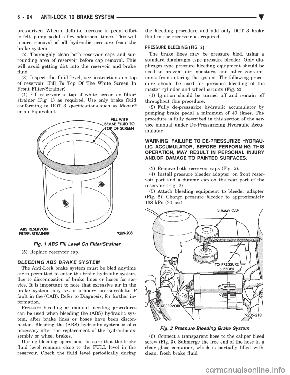
Front Filter/Strainer). (4) Fill reservoir to top of white screen on filter/
strainer (Fig. 1) as required. Use only brake fluid
conforming to DOT 3 specifications such as Mopar t
or an Equivalent.
(5) Replace reservoir cap.
BLEEDING ABS BRAKE SYSTEM
The Anti-Lock brake system must be bled anytime
air is permitted to enter the brake hydraulic system,
due to disconnection of brake lines or hoses for ser-
vice. It is important to note that excessive air in the
brake system may set a primary pressure/delta P
fault in the (CAB). Refer to Diagnosis, for further in-
formation. Pressure bleeding or manual bleeding procedures
can be used when bleeding the (ABS) hydraulic sys-
tem, after brake lines or hoses have been discon-
nected. Bleeding the (ABS) hydraulic system is also
necessary after the replacement of the hydraulic as-
sembly or wheel brakes. During bleeding operations, be sure that the brake
fluid level remains close to the FULL level in the
reservoir. Check the fluid level periodically during the bleeding procedure and add only DOT 3 brake
fluid to the reservoir as required.
PRESSURE BLEEDING (FIG. 2)
The brake lines may be pressure bled, using a
standard diaphragm type pressure bleeder. Only dia-
phragm type pressure bleeding equipment should be
used to prevent air, moisture, and other contami-
nants from entering the system. The following proce-
dure should be used for pressure bleeding of the
master cylinder and wheel circuits (Fig. 2) (1) Ignition should be turned off and remain off
throughout this procedure. (2) Fully de-pressurize hydraulic accumulator by
pumping brake pedal a minimum of 40 times. The
procedure is fully described in this section of the ser-
vice manual under De-Pressurizing Hydraulic Accu-
mulator.
WARNING: FAILURE TO DE-PRESSURIZE HYDRAU-
LIC ACCUMULATOR, BEFORE PERFORMING THIS
OPERATION, MAY RESULT IN PERSONAL INJURY
AND/OR DAMAGE TO PAINTED SURFACES.
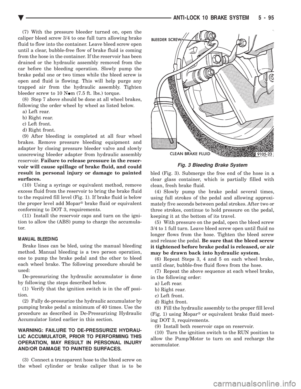
(3) Remove both reservoir caps (Fig. 2).
(4) Install pressure bleeder adapter, on front reser-
voir port and a dummy cap on the rear port of the
reservoir (Fig. 2) (5) Attach bleeding equipment to bleeder adapter
(Fig. 2). Charge pressure bleeder to approximately
138 kPa (20 psi).
(6) Connect a transparent hose to the caliper bleed
screw (Fig. 3). Submerge the free end of the hose in a
clear glass container, which is partially filled with
clean, fresh brake fluid.
Fig. 1 ABS Fill Level On Filter/Strainer
Fig. 2 Pressure Bleeding Brake System
5 - 94 ANTI-LOCK 10 BRAKE SYSTEM Ä
Page 245 of 2438
(7) With the pressure bleeder turned on, open the
caliper bleed screw 3/4 to one full turn allowing brake
fluid to flow into the container. Leave bleed screw open
until a clear, bubble-free flow of brake fluid is coming
from the hose in the container. If the reservoir has been
drained or the hydraulic assembly removed from the
car before the bleeding operation. Slowly pump the
brake pedal one or two times while the bleed screw is
open and fluid is flowing. This will help purge any
trapped air from the hydraulic assembly. Tighten
bleeder screw to 10 N Im (7.5 ft. lbs.) torque.
(8) Step 7 above should be done at all wheel brakes,
following the order wheel by wheel as listed below. a) Left rear.
b) Right rear.
c) Left front.
d) Right front.
(9) After bleeding is completed at all four wheel
brakes. Remove pressure bleeding equipment and
adapter by closing pressure bleeder valve and slowly
unscrewing bleeder adapter from hydraulic assembly
reservoir. Failure to release pressure in the reser-
voir will cause spillage of brake fluid, and could
result in personal injury or damage to painted
surfaces. (10) Using a syringe or equivalent method, remove
excess fluid from the reservoir to bring the brake fluid
to the required fill level (Fig. 1). If brake fluid is below
the proper level add Mopar tbrake fluid or equivalent
conforming to DOT 3, requirements. (11) Install the reservoir caps and turn on the igni-
tion to allow the (ABS) pump to charge the accumula-
tor.
MANUAL BLEEDING
Brake lines can be bled, using the manual bleeding
method. Manual bleeding is a two person operation,
one to pump the brake pedal and the other to bleed
each wheel brake. The following procedure should be
used: De-pressurizing the hydraulic accumulator is done
by following the steps described below. (1) Verify that the ignition switch is in the off posi-
tion. (2) Fully de-pressurize the hydraulic accumulator by
pumping brake pedal a minimum of 40 times. Use the
procedure as described in De-Pressurizing Hydraulic
Accumulator listed earlier in this section.
WARNING: FAILURE TO DE-PRESSURIZE HYDRAU-
LIC ACCUMULATOR, PRIOR TO PERFORMING THIS
OPERATION, MAY RESULT IN PERSONAL INJURY
AND/OR DAMAGE TO PAINTED SURFACES.
(3) Connect a transparent hose to the bleed screw on
the wheel cylinder or brake caliper that is to be bled (Fig. 3). Submerge the free end of the hose in a
clear glass container, which is partially filled with
clean, fresh brake fluid.
(4) Slowly pump the brake pedal several times,
using full strokes of the pedal and allowing approxi-
mately five seconds between pedal strokes. After two or
three strokes, continue to hold pressure on the pedal,
keeping it at the bottom of its travel. (5) With pressure on the pedal, open the bleed screw
3/4 to 1 full turn. Leave bleed screw open until fluid no
longer flows from the hose. Tighten the bleed screw
and release the pedal. Be sure that the bleed screw
it tightened before brake pedal is released, or air
may be drawn back into hydraulic system. (6) Repeat Steps 3, 4 and 5 on each wheel brake,
until clear, bubble-free fluid flows from the hose. (7) Repeat the above sequence at each wheel brake,
in the following order: a) Left rear.
b) Right rear.
c) Left front.
d) Right front.
(8) Fill the hydraulic assembly to the proper fill level
(Fig. 1) using Mopar tor equivalent brake fluid meet-
ing DOT 3, requirements. (9) Install both reservoir caps on reservoir.
(10) Turn the ignition switch to the RUN position to
allow the Pump/Motor to turn on and recharge the
accumulator.
Fig. 3 Bleeding Brake System
Ä ANTI-LOCK 10 BRAKE SYSTEM 5 - 95