1992 MAZDA PROTEGE window
[x] Cancel search: windowPage 931 of 1164

REAR WINDOW DEFROSTER T
TROUBLESHOOTING
Circuit Diagram
. .-
m DIGITAL CLOCK WXGARETTE LIGHTER I-l
f$pjg
MAIN
BOA BTN
60A v v
0. o! B (E)
l- IX-0 lJ
Ix-u REAR WINDOW DEFROSTER SWITCH TI LUMINATION LAMP: REFER TO JB-05 a
CTION I-4
I nnnt.,4
.L (F)
SE
JB-02LJ:t=;GJB-06
a3 ,, ,, @
I \\- //
B/W (I)
ET?-- (F)
5 JB-06 @
RADIO
15A
JB-02 0
1 ,“Yll IOA
JB-02 0
REAR WINDOW
m&R;~TER I
4 JB-02 @+ PRTEGE i
IV
tr I
I+ LA.“, I I\-1 I
I - -
_--___---
_._- ------
I 2s 1 w
rzlznl+ I I (3
I I -. .--. .- tNGlNt CONTROL UNIT
(SECTION
B-;c. 2b)
REAR WINDOW
DEFROSTER
PRO,TEGE ,/ ILLUMINATION
LAMPS
(SECTION I-4)
‘-01
REAR WINDOW I-02 REAR WINDOW I-03 CIGARETTE
jEFROSTER SWITCH (1)
* B/L R/B
B B/W R
03UOTX-124
T-75
Page 932 of 1164

REAR WINDOW DEFROSTER
Defroster does not operate
1
Check defog 20A fuse Short circuit (Broken wire)
0 OK
Turn Ign switch to ON
Confirm battery voltage on B/W wire of rear window
defroster switch Repair harness (Fuse - Rear window defroster switch)
0 1 OK
Confirm battery voltage on B/L wire of rear window
defroster switch with the switch ON
I NG
) Check rear window defroster switch
(Refer to page T-77)
0 OK
With the switch ON, confirm battery voltage on B/L wire NG ) Repair harness (Rear window defroster switch -
of the defroster filament Filament)
I
0 1 OK -1 NG
Confirm OV on B wire of the defroster filament - Faulty grounding
Check filament (Refer to page T-77)
23UOTX-047
T-76
Page 933 of 1164

REAR WINDOW DEFROSTER
OBUOTX-12
/--FAULTY PORTION
c;lm @$J-p>
ov I
APPROX. 12V
BROKEN WIRE TAPE
\-hf
I ‘.
11 fi I
Y CORRECTION PORTION
OSUOTX-12
FILAMENT
inspection
1. Turn the rear window defroster switch ON.
2. Connect the (+) terminal of the voltmeter to the center of
each filament and the (-) terminal to the body. The stan-
dard voltage at the center of each filament is approximate-
ly 6V. If the meter indication is high, there is a short circuit
between the center and the grounded side of the filament.
If the indication is low or zero, the malfunction is between
the center and positive side.
Repairing
7. Use paint thinner or ethyl alcohol to clean the damaged part
of the filament.
2. Attach tape to both sides of the damaged part of the filament.
3. Using a small brush or marking pen, coat the damaged part
with silver paint (part no. 2835 77 600) or equivalent.
4. Let the paint set for 24 hours at 25OC (77OF) to let it dry
completely. (If a blow dryer is used to heat it to 150°C
(302OF), it can be dried in about 30 minutes.)
Note
l Do not use the rear window defroster until the paint
is dry.
l Do not use gasoline or sDmiiar solvents to clean the
damaged part.
REAR WINDOW DEFROSTER SWITCH
inspection
1. Check for continuity between the terminals with an
ohmmeter.
O--O : indicates continuity
1 J
03UOTX-128
T-77
Page 953 of 1164

AUDIO T
Noise Suppression Chart
Cause
‘uel pump noise Remedy Move speaker wiring away from fuel pump wire.
REAR HARNESS FUEL
PUMP
Wotor noise
Wiper, washer, power
window, for example) 1. Check grounding.
2. Install condensers to motor circuit.
Turn signal noise Connect condenser (0.5 pF) to power line of filter unit. Note
CONDENSER
4lternator noise
l Condenser should be placed near flasher unit.
Connect condenser (0.5 pF) near alternator.
TO RADIO
CONDENSER
97UOTX-1
T-97
Page 992 of 1164

U AIR CONDITIONER
DRY AND WET THERMOMETER
13uoux-014
Performance test
After finishing repairs, conduct a performance test of the air
conditioning system as follows.
1. Connect the manifold gauge set. (Refer to page U-32.)
2. Start the engine and keep the engine speed at
1,500 rpm.
3. Operate the air conditioner at maximum cooling.
4. Open all windows and doors.
5. Place a dry-bulb thermometer in the center ventilator outlet.
6. Place a dry and wet thermometer close to the blower inlet.
7. Wait until the air conditioner outlet temperature stabilizes.
Stabilized condition
Blower inlet temperature: 25-35*C (77-95*F)
High-pressure side:
1,177-1,619 kPa (12.0-16.6 kg/cm’, 171-235 psi)
Note
l If the high-pressure side becomes too high, pour
cool water on the condenser. If It is too low, cover
the front of the condenser.
8. After the air conditioner stabilizes, read the dry and wet ther-
mometer at the air inlet.
9. Calculate the relative humidity from the chart below by com-
paring the wet- and dry-bulb readings.
05uoux-051
‘C ‘F
26
24
22
20
18
16
14
12
10
U
--k----
RELATIVE HUMIDITY ‘%’
I 96U16X.103
IO. Read the dry thermometer at the air outlet, and calculate
the difference between the inlet dry-bulb and outlet dry-bulb
temperatures.
11. Verify that the intersection of the relative humidity and tem-
perature difference is in the shaded zone.
U-36
Page 1047 of 1164

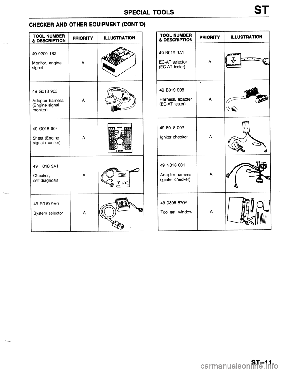
SPECIAL TOOLS ST
CHECKER AND OTHER EQUIPMENT (CONT’D)
49 9200 162
Monitor, engine
49 GO18 903
Adapter harness
49 GO18 904
Sheet (Engine
49 HO18 9Al
49 B019 9AO
System selector TOOL NUMBER
L DESCRIPTION PRIORITY ILLUSTRATION
19 BO19 9Al
X-AT selector
EC-AT tester) A .
19 B019 908
larness, adapter A
;EC-AT tester)
49 FO18 002
Igniter checker A
49 NO18 001
Adapter harness A
(igniter checker)
49 0305 870A
Tool set, window A
ST-l 1
Page 1050 of 1164

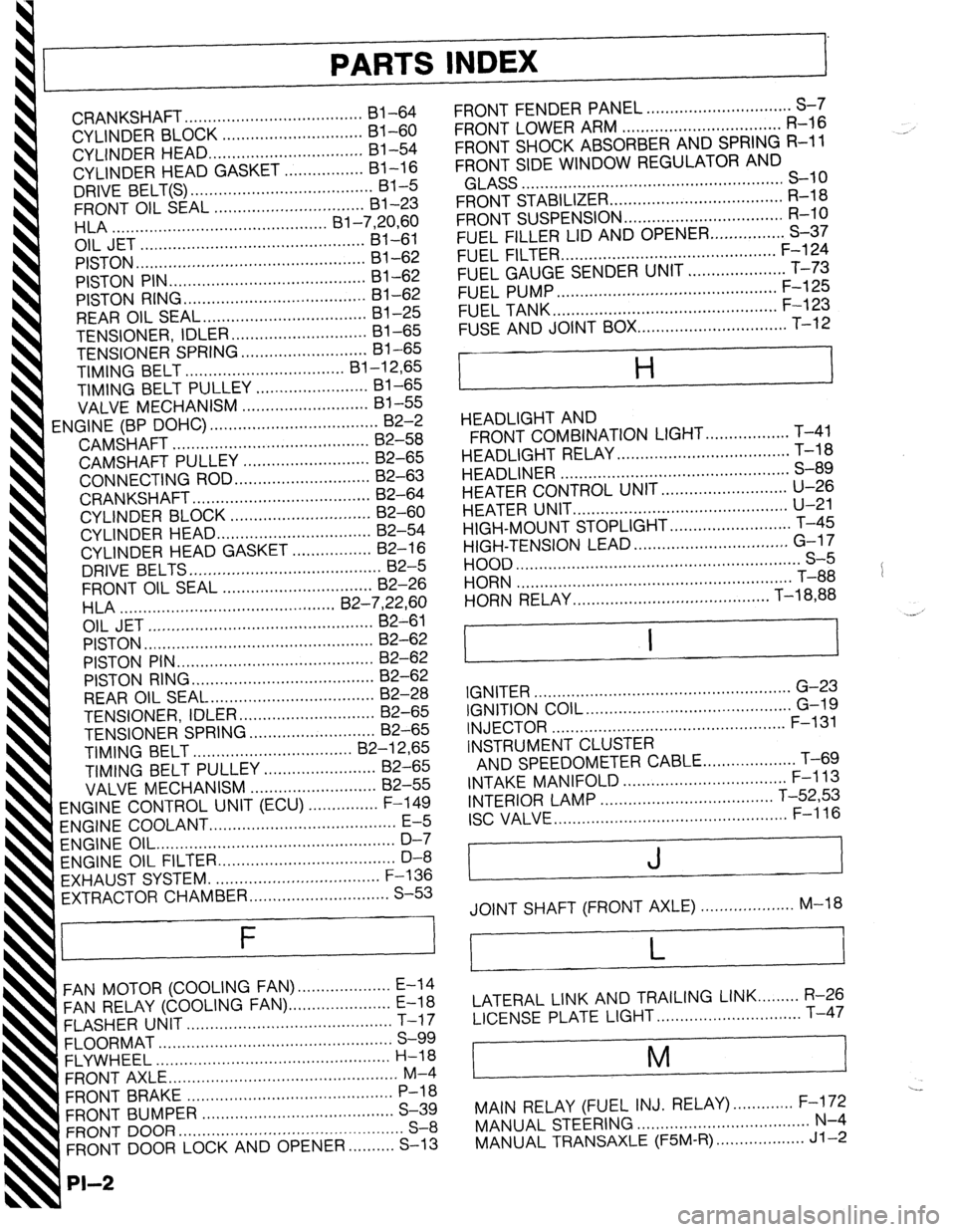
PARTS INDEX
I
CRANKSHAFT.. ....................................
I31 -64
CYLINDER BLOCK .............................. 61-60
CYLINDER HEAD..
............................... 81-54
CYLINDER HEAD GASKET .................
Bl-16
DRIVE BELT(S). ...................................... 81-5
FRONT OIL SEAL ................................ 81-23
HLA .............................................. Bl-7,20,60
OIL JET ................................................ 81-61
PISTON.. ...............................................
Bl-62
PISTON PIN..
........................................ 81-62
PISTON RING
....................................... 81-62
REAR
OIL SEAL..
................................. 81-25
TENSIONER, IDLER ............................. Bl-65
TENSIONER
SPRING ...........................
Bl-65
TIMING BELT ..................................
Bl-12,65
TIMING BELT PULLEY ........................
Bl-65
VALVE MECHANISM ........................... Bl-55
ENGINE
(BP DOHC) .................................... B2-2
CAMSHAFT ..........................................
82-58
CAMSHAFT PULLEY ...........................
B2-65
CONNECTING ROD..
........................... 82-63
CRANKSHAFT ......................................
B2-64
CYLINDER BLOCK ..............................
82-60
CYLINDER
HEAD.. ............................... B2-54
CYLINDER HEAD GASKET .................
82-16
DRIVE
BELTS.. .......................................
B2-5
FRONT
OIL SEAL ................................
82-26
H LA ..............................................
OIL JET .......................... B2-7iyL;;
......................
PISTON .................................................
B2-62
PISTON PIN ..........................................
82-62
PISTON RING..
..................................... 82-62
REAR OIL SEAL ................................... B2-28
TENSIONER, IDLER ............................. B2-65
TENSIONER SPRING ........................... B2-65
TIMING
BELT.. ................................
B2-12,65
TIMING BELT PULLEY ........................ 82-65
VALVE MECHANISM ........................... 82-55
ENGINE CONTROL UNIT (ECU) ............... F-149
ENGINE COOLANT
........................................ E-5
ENGINE OIL.. .................................................
D-7
ENGINE OIL FILTER.. .................................... D-8
’ EXHAUST SYSTEM. ...................................
F-136
EXTRACTOR CHAMBER .............................. S-53
F
FAN MOTOR (COOLING FAN). ................... E-14
FAN RELAY (COOLING FAN). ..................... E-18
FLASHER UNIT ............................................
T-17
FLOORMAT ..................................................
S-99
FLYWHEEL ..................................................
H-18
FRONT AXLE .................................................
M-4
FRONT BRAKE ............................................
P-l 8
FRONT BUMPER ......................................... S-39
FRONT DOOR ................................................
S-8
FRONT DOOR LOCK AND OPENER ..........
S-13
PI-2
FRONT FENDER PANEL ............................... S-7
FRONT LOWER ARM .................................. R-16
FRONT SHOCK ABSORBER AND SPRING R-11
FRONT SIDE WINDOW REGULATOR AND
GLASS ........................................................ S-10
FRONT STABILIZER..
................................... R-l 8
FRONT SUSPENSION .................................. R-l 0
FUEL FILLER LID AND OPENER..
.............. S-37
FUEL FILTER .............................................. F-l 24
FUEL GAUGE SENDER UNIT ..................... T-73
FUEL PUMP ............................................... F-125
FUEL TANK
................................................ F-123
FUSE AND JOINT BOX.. .............................. T-12
H
HEADLIGHT AND
FRONT COMBINATION LIGHT..
................ T-41
HEADLIGHT RELAY ..................................... T-l 8
HEADLINER ................................................. S-89
HEATER CONTROL UNIT.. ......................... U-26
HEATER UNIT
.............................................. U-21
HIGH-MOUNT STOPLIGHT
.......................... T-45
HIGH-TENSION LEAD ................................. G-l 7
HOOD ............................................................. S-5
HORN T-88
...........................................................
HORN RELAY
.......................................... T-18,88
.__. ’
I I
IGNITER .......................................................
G-23
IGNITION COIL.. .......................................... G-19
INJECTOR .................................................. F-l 31
INSTRUMENT CLUSTER
AND SPEEDOMETER CABLE
.................... T-69
INTAKE MANIFOLD ................................... F-113
INTERIOR LAMP ..................................... T-52,53
ISC VALVE.. ................................................ F-l 16
J
JOINT SHAFT (FRONT AXLE) .................... M-18
L
LATERAL LINK AND TRAILING LINK.. ....... R-26
LICENSE PLATE LIGHT.. ............................. T-47
i
M
I
---
MAIN RELAY (FUEL INJ. RELAY). ............ F-172
MANUAL STEERING ..................................... N-4
MANUAL TRANSAXLE (F5M-R). .................. Jl-2
Page 1051 of 1164

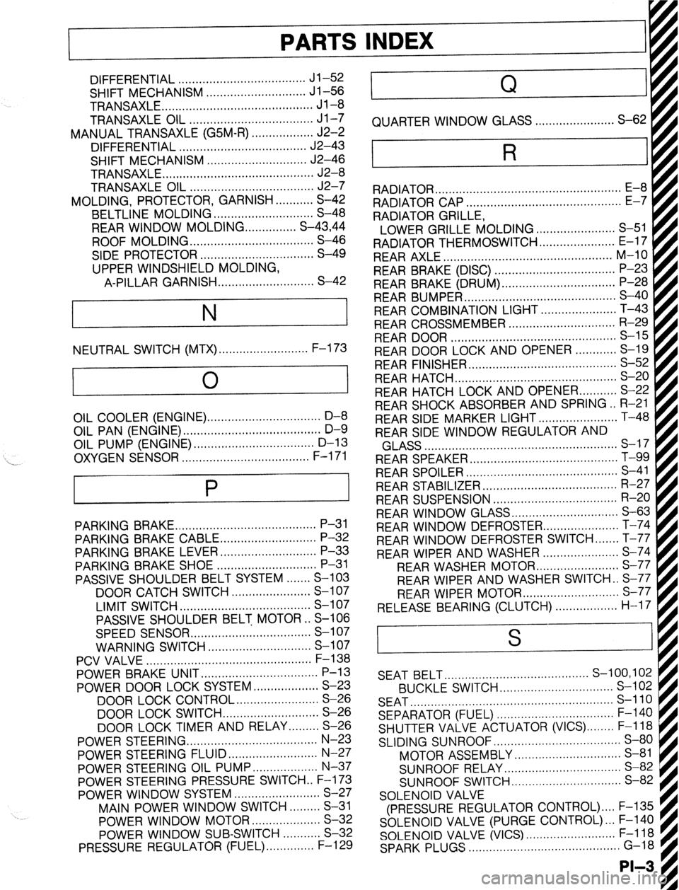
PARTS
DIFFERENTIAL ..................................... Jl-52
SHIFT MECHANISM ............................. Jl-56
TRANSAXLE ............................................ Jl-8
TRANSAXLE OIL .................................... Jl-7
MANUAL TRANSAXLE (G5M-R) .................. J2-2
DIFFERENTIAL ..................................... J2-43
SHIFT MECHANISM ............................. J2-46
TRANSAXLE.. .......................................... J2-8
TRANSAXLE OIL .................................... J2-7
MOLDING, PROTECTOR, GARNISH ...........
S-42
BELTLINE MOLDING ............................. S-48
REAR WINDOW MOLDING.. ............. S-43,44
ROOF MOLDING.. .................................. S-46
SIDE PROTECTOR ................................. S-49
UPPER WINDSHIELD MOLDING,
A-PILLAR GARNISH ............................ S-42
NEUTRAL SWITCH (MTX) . . . . . . . . . . . . . . . . . . . . . . . . . . F-l 73
0
1
\_ OIL COOLER (ENGINE). ................................ D-8
OIL PAN (ENGINE) ........................................ D-9
OIL PUMP (ENGINE) ................................... D-l 3
..................................... F-l 71
OXYGEN SENSOR
P
PARKING BRAKE ......................................... P-31
PARKING BRAKE CABLE ............................ P-32
PARKING BRAKE LEVER ............................ P-33
PARKING BRAKE SHOE ............................. P-31
PASSIVE SHOULDER BELT SYSTEM.. ..... S-103
DOOR CATCH SWITCH ....................... S-l 07
LIMIT SWITCH ...................................... S-l 07
PASSIVE SHOULDER BELT MOTOR.. S-106
SPEED SENSOR ................................... S-l 07
WARNING SWITCH .............................. S-l 07
PCV VALVE ................................................
POWER BRAKE UNIT ‘;--=I;;
..................................
POWER DOOR LOCK SYSTEM ................... S-23
DOOR LOCK CONTROL.. ...................... S-26
DOOR LOCK SWITCH.. .......................... S-26
DOOR LOCK TIMER AND RELAY.. ....... S-26
POWER STEERING.. .................................... N-23
POWER STEERING FLUID .......................... N-27
POWER STEERING OIL PUMP.. ................. N-37
POWER STEERING PRESSURE SWITCH . . F-l 73
POWER WINDOW SYSTEM.. .......................
S-27
MAIN POWER WINDOW SWITCH.. .......
S-31
POWER WINDOW MOTOR.. ..................
S-32
POWER WINDOW SUB-SWITCH ........... S-32
PRESSURE REGULATOR (FUEL). ............. F-l 29 . . . . . . . . , . . . . . , . RADIATOR CAP .............................................
E-7
RADIATOR GRILLE,
I
LOWER GRILLE MOLDING ....................... S-51 fl
RADIATOR THERMOSWITCH ...................... E-17 t
REAR AXLE ................................................. M-10
REAR BRAKE (DISC) ................................... P-23
REAR BRAKE (DRUM) ................................. P-28
REAR BUMPER ............................................ s-40
REAR COMBINATION LIGHT.. ....
REAR CROSSMEMBER ............................... R-29
REAR DOOR ................................................ S-l 5
REAR DOOR LOCK AND OPENER.. .
REAR FINISHER ........................................... s-52
REAR HATCH ............................................... s-20
REAR HATCH LOCK AND OPENER.. ......... S-22
REAR SHOCK ABSORBER AND SPRING.. R-21
REAR SIDE MARKER LIGHT ....................... T-48
REAR SIDE WINDOW REGULATOR AND . . . . . . . . .
AI .,.n
INDEX
Q
QUARTER WINDOW GLASS . . . . . . . . . . . . ..a........ S-62
R
RADIATOR . . . . . . . . . . . . . . . . . . . . . . . . . . . . . . . . . . . . . . . . . . . . . . . . . . . . . .
kiLA33 ........................................................ a-- I I
REAR SPEAKER ........................................... T-99
REAR SPOILER ............................................ s-41
REAR STABILIZER.. ..................................... R-27
REAR SUSPENSION .................................... R-20
REAR WINDOW GLASS ............................... S-63
REAR WINDOW DEFROSTER.. .................... T-74
REAR WINDOW DEFROSTER SWITCH ....... T-77
REAR WIPER AND WASHER ...................... S-74
REAR WASHER MOTOF
REAR WIPER AND WASHER SWITCH . . S-77
REAR WIPER MOTOR ............................ s-77
RELEASE BEARING (CLUTCH). . . . . . . . . . ..s..... H-17 I . . . . . . . . ...*. .*......*..
SEAT BELT.. ........................................ S-100,102
BUCKLE SWITCH.. ............................... S-l 02
SEAT ........................................................... s-110
SEPARATOR (FUEL) .................................. F-l 40
SHUTTER VALVE ACTUATOR (VICS) ........ F-l 18
SLIDING SUNROOF ..................................... S-80
MOTOR ASSEMBLY ............................... S-81
SUNROOF RELAY.. ................................ S-82
SUNROOF SWITCH.. .............................. S-82
SOLENOID VALVE
(PRESSURE REGULATOR CONTROL) .... F-135
SOLENOID VALVE (PURGE CONTROL). .. F-140
SOLENOID VALVE (VICS) .......................... F-l 18
SPARK PLUGS ............................................ G-18
-II__