Page 992 of 1164

U AIR CONDITIONER
DRY AND WET THERMOMETER
13uoux-014
Performance test
After finishing repairs, conduct a performance test of the air
conditioning system as follows.
1. Connect the manifold gauge set. (Refer to page U-32.)
2. Start the engine and keep the engine speed at
1,500 rpm.
3. Operate the air conditioner at maximum cooling.
4. Open all windows and doors.
5. Place a dry-bulb thermometer in the center ventilator outlet.
6. Place a dry and wet thermometer close to the blower inlet.
7. Wait until the air conditioner outlet temperature stabilizes.
Stabilized condition
Blower inlet temperature: 25-35*C (77-95*F)
High-pressure side:
1,177-1,619 kPa (12.0-16.6 kg/cm’, 171-235 psi)
Note
l If the high-pressure side becomes too high, pour
cool water on the condenser. If It is too low, cover
the front of the condenser.
8. After the air conditioner stabilizes, read the dry and wet ther-
mometer at the air inlet.
9. Calculate the relative humidity from the chart below by com-
paring the wet- and dry-bulb readings.
05uoux-051
‘C ‘F
26
24
22
20
18
16
14
12
10
U
--k----
RELATIVE HUMIDITY ‘%’
I 96U16X.103
IO. Read the dry thermometer at the air outlet, and calculate
the difference between the inlet dry-bulb and outlet dry-bulb
temperatures.
11. Verify that the intersection of the relative humidity and tem-
perature difference is in the shaded zone.
U-36
Page 996 of 1164

U AIR CONDITIONER
OFF
03UOUX-06
03UOUX-06,
03UOUX-06
On-vehicle Inspection
Thermoswitch
1. Remove the glove box.
2. Run the engine at idle.
3. Turn OFF the A/C switch and set the blower switch to the
highest position to operate the blower fan for a few minutes.
4. After a few minutes, turn OFF the blower switch and stop
the engine.
5. Disconnect the thermoswitch connector and check for con-
tinuity between terminals of the switch.
Terminals Continuity
a-b Yes
6. If not as specified, replace the thermoswitch.
Note
l The thermoswitch contacts will be open if the
evaporator temperature is below 0.4 f 0.7OC (32.7
z!z 1.3OF).
Inspection
Thermoswitch
1. Immerse the sensing bulb in a container of ice water.
2. Check continuity between terminals of the switch as
specified.
Terminals
a-b Temperature Continuity
Above 5°C Yes
Below 0% No
3. If not as specified, replace the thermoswitch
Evaporator
1. Check the evaporator fins for blockage. If the fins are
clogged, clean them with compressed air.
Caution
l Never use water to clean the evaporator.
2. Check the fittings for cracks and other damage.
Replace the evaporator if necessary.
u-40
Page 1034 of 1164

TD TECHNICAL DATA
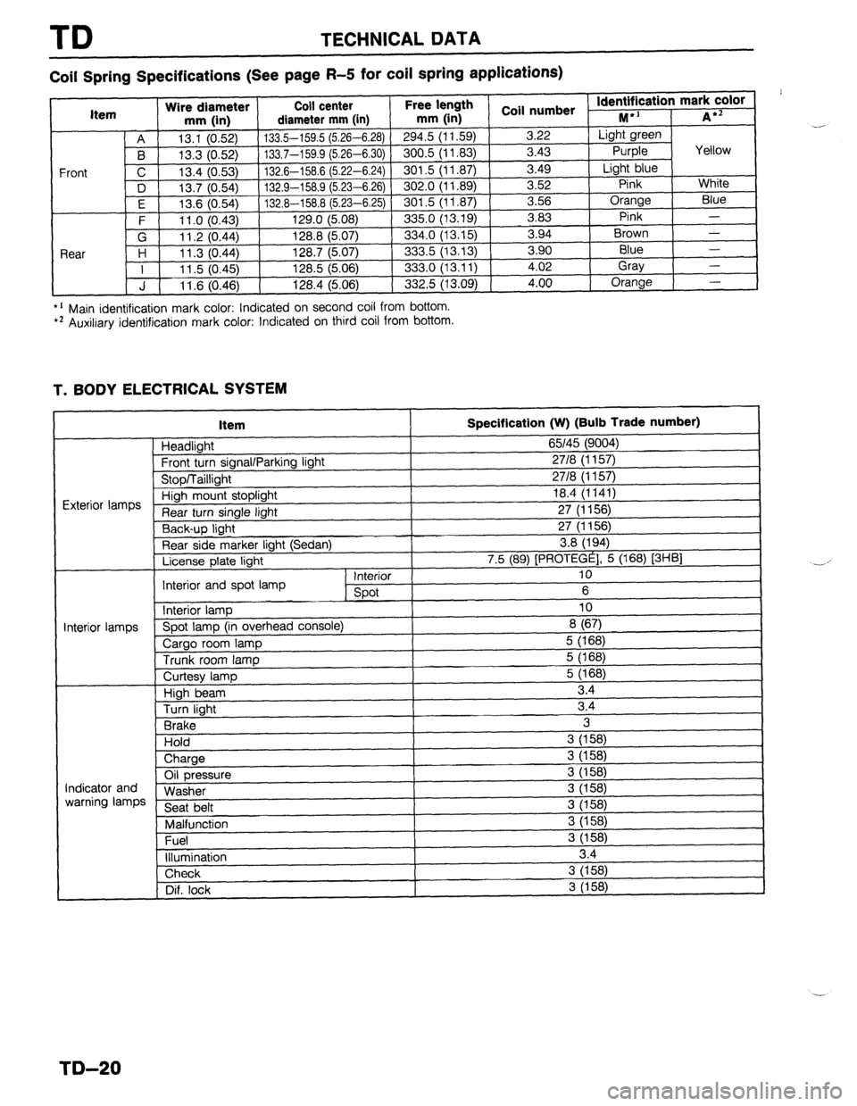
Coil Spring Specifications (See page R-5 for coil spring applications)
*’ Main identification mark color: Indicated on second coil from bottom. l * Auxiliary identification mark color: Indicated on third coil from bottom.
T. BODY ELECTRICAL SYSTEM
Item
Headlight
Frnnt tl wn sinnnl/Pnrkinn linht
Specification (W) (Bulb Trade number)
65145 (9004)
2718 II I 571
I
“‘VW, I u”“y’ 1. I” \’ ‘V’,
uinh mount stoplight 18.4 (1141)
turn single light 27 (1156)
Y-,-~p light 27 (1156)
Rear side marker light (Sedan) 3.8 (194)
License plate light 7.5 (89) [PROTEGE], 5 (168) [3HBl
Interior 10
Interior and spot lamp
spot 6
Interior lamp 10
‘i--” Spot lamp (in overhead console)
8 (67)
Cargo room lamp 5 (168)
Trunk room lamp 5 (168)
I I
ntminr Iamnc
I
Curtesy lamp
High beam
Turn light
Brake
Hold
) Charge 5 (168)
3.4
3.4
3
3 (158)
i
Oil pressure
Washer
Seat belt
Malfunction
Fuel
illumination 3 (158)
3 (158)
3 (158)
3 (158)
3 (158)
3 (158)
3.4 Indicator and
warning lamps
Check 3 (158)
Dif. lock
I 3 (158) .-
,
-.-’
I
I
TD-20
Page 1065 of 1164

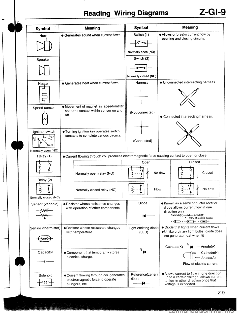
Reading Wiring Diagrams Z-GI-9
Symbol ‘ Meaning Symbol Meaning
Horn l Generates sound when current flows. Switch (1) l Allows or breaks current flow by
opening and closing circuits.
Speaker
w
Heater l Generates heat when current flows. Normally open (NO)
Switch (2)
Normally closed (NC)
Harness l Unconnected intersecting harness.
Speed sensor l Movement of magnet in speedometer
set turns contact within sensor on and
Off. (Not connected)
l Connected intersecting harness.
Ignition switch @Turning ignition key operates switch
contacts to complete various circuits.
(Connected)
rlormally open (NO)
Relay (1) l Current flowing through coil produces electromagnetic force causing contact to open or close.
____- .~.~~
Open Closed
--.--.-m.---------,
Relay (2) Normally open relay (NO)
- Ri i No flow ’ ni 1 Closed
Normally closed relay (NC) Flow
ormally closed (NC)
Sensor (variable) l Resistor whose resistance changes Diode
l Known as a semiconductor rectifier.
--3p6G- with operation of other components. diode allows current flow in one
direction only
--T- IA
IY Calhode(K)+- Anode(A)
* Flow of electric current
K-1 KD, he>:
-
ensor (thermistor)
l Resistor whose resistance changes Light emitting diode 0 Diode that lights when current flows
with temperature.
(LED)
l Unlike ordinary light bulbs, diode does
not generate heat when lit
Capacitor
l Component that temporarily stores “2, Cathode(K) --&---Anode(A)
I7
Cathode(K)
electrical charge.
c Anode(A)
----il---- .
Flow of electric current
Solenoid
l Current flowing through co11 generates Reference(zener) l Allows current to flow In one dlrectlon
electromagnetic force to operate diode up to a certain voltage. allows current
plungers, etc. cd to flow In other dIrectron once that
J-
voltage IS exceeded.
z-9
Page 1069 of 1164

Troubleshooting Z-Gl-13
el
-
Ill
31
-
I1
Jl
:n
r.
7a
ver
le
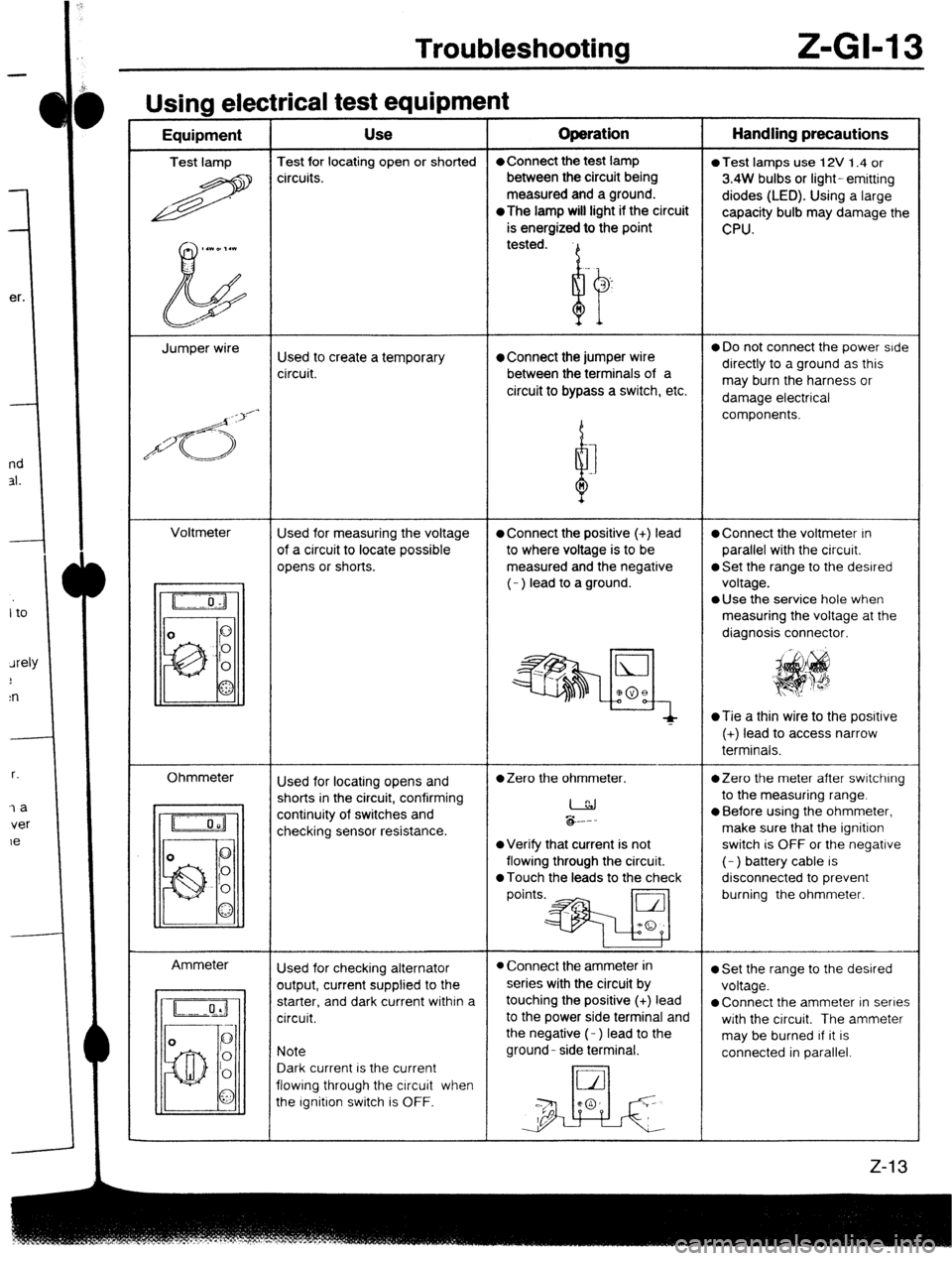
Usina electrical test eaubment -----w - I - Equipment Use Operation Handling precautions
Test lamp Test for locating open or shorted l Connect the test lamp
0 Test lamps use 12V 1.4 or
R circuits. between the circuit being
3.4W bulbs or light- emitting
measured and a ground.
diodes (LED). Using a large
*The
lamp will light if the circuit
capacity bulb may damage the
is energized to the point
CPU.
,.WD,.l
b tested.
Jumper wire
Used to create a temporary l Connect the jumper wire 0 Do not connect the power side
circuit. between the terminals of a directly to a ground as this
circuit to bypass a switch, etc. may burn the harness or
damage electrical
/d<;>‘-
d components.
I
n
Voltmeter
Used for measuring the voltage
l Connect the positive (+) lead l Connect the voltmeter In
of a circuit to locate possible to where voltage is to be parallel with the circuit.
opens or shorts. measured and the negative
0 Set the range to the desired
(- ) lead to a ground. voltage.
l Use the service hole when
measuring the voltage at the
diagnosis connector.
~Tie a thin wire to the posrtive
(+) lead to access narrow
terminals.
Ohmmeter
Ammeter Used for locating opens and
l Zero the ohmmeter. *Zero the meter after switching
shorts in the circuit, confirming
I to the measuring range.
continuity of switches and
checking sensor resistance. &.--
l Before using the ohmmeter,
make sure that the ignition
l Verify that current is not switch is OFF or the negative
flowing through the circuit. (- ) battery cable is
0 Touch the leads to the check disconnected to prevent
points.* burning the ohmmeter.
Used for checking alternator
l Connect the ammeter in l Set the range to the desired
output, current supplied to the series with the circuit by
voltage.
starter, and dark current within a touching the positive (+) lead
l Connect the ammeter in series
circuit. to the power side terminal and
with the circuit. The ammeter
the negative (- ) lead to the
may be burned If it is
Note ground- side terminal.
connected in parallel.
Dark current is the current
flowing through the circuit when
the Ignition switch is OFF.
Page 1110 of 1164
WlRlNQ DIMRAM
IITHOUT
:RUISE CONTROL’ HEADL1GHTS E-l
ILLUMINATION
BULB TRADE NUMBER
HEADLIGHT: 9004 (65/45W)
-01 COMBINATION E-02 COMBINATION E-03 HEADLIGHT LH (F) E-04 HEADLIGHT RH (F:
Page 1112 of 1164
WIUINW lJlAWnAm
JITH
mJI:SE CONTROL
l HEADLIGHTS E-2
DRL CONTROL
DRL CONTROL
qE-04 BULB TRADE NUMBER
HEADLIGHT: 9004 (65/45W)
f v
t-02 COMBINATION
SWITCH (F) E-03 HEADLIGHT LH(F) E-04 HEADLIGHT RH(F) E-05 HEADLIGHT RE;$
”
R/W R W/R
B L/Y LG
E-06 TAILLIGHT REU&
.
Z-56
Page 1116 of 1164
! WIRINQ DIAQRAN
l TAILLIGHTS
l LICENSE PLATE LIGHTS mREAR SIDE MARKER LIGHTS n POSITiON LIGHTS E-4
ti;$ik;GHT
(SECTION E-l. 2)
BULB TRADE NUMBER
REAR SIDE MARKER: 194 (3.BW1
TAILLIGHT: 1157 (8W) BULB TRADE NUMBER
LICENSE PLATE: 89 (7.5W1
POSITION. 1157 (8W)
-
I PROTFGF I PROTEGE
SIDE
-n TAILLIGHT Ll ‘-I I , PROTEGE
I k PROTEGE 1
I J
R a I i H“
ION
LH
-10 REAR SIDE MARKER E-II REAR SIDE MARKER E-12 TAILLIGHT LH (R) E-13 TAILLIGHT RH (R)
LIGHT LH (R) LIGHT RH (R) E-14 LICENSE PLATE LI;li;E-I” LICENSE PLATE LK;:‘E-I” LICENSE PLATE L$j;
-17 POSITION LIGHT c;r E-18 POSITION LIGHTRji