1992 MAZDA PROTEGE oil capacity
[x] Cancel search: oil capacityPage 551 of 1164

OUTLINE J2
OUTLINE
SPECIFICATIONS
Item
Transaxle control
Synchromesh system EnginelTransaxle
BP DOHC
GSM-R Floor shift
Forward: Synchromesh
Reverse: Selective sliding and synchromesh
T- I-
Gear ratio
I
1 st 3.307
2nd 1.833
3rd 1.310
4th 1.030
5th 0.795
Reverse 3.166
Final gear ratio 4.105
q
Oil Viscosity All-season
Above -18OC (OOF) ATF DexronYI, M2C33F or SAE75W-80
API service GL-4 SAE80W-90
Capacity liters (US qt, Imp qt) 3.35 (3.55, 2.96)
23UOJ2-001
52-3
Page 555 of 1164

TRANSAXLE OIL 52
03UOJ2-00’
03UOJ2-008
03UOJ2-00
1 9
23UOJ2-002
TRANSAXLE OIL
INSPECTION
Note
l Park the vehicle on level ground.
1. Disconnect the speedometer cable and remove the speedo-
meter driven gear.
2. Verify that the oil level is between F and L.
3. Install the speedometer driven gear.
Tightening torque:
7.8-12 Nmrn (80-120 cm-kg, 89-104 in-lb)
4. Connect the speedometer cable.
REPLACEMENT
1. Disconnect the speedometer cable and remove the speedo-
meter driven gear.
2. Remove the drain plug and washer. Drain the oil into a suit-
able container.
3. Install a new washer and the drain plug.
Tightening torque:
39-59 N*m (4.0-8.0 m-kg, 29-43 ft-lb)
4. Add the necessary amount of the specified oil through the
speedometer gear case hole.
Specified oil
Viscosity: All-season ATF Dexron@lI, M2C33F or
SAE75W-80
Above -18*C (O*F) API service GL-4
SAE 8OW-90
Capacity: 3.35 liters (3.55 US qt, 2.96 Imp qt)
5. Verify the oil level.
6. Install the speedometer driven gear and connect the
speedometer cable.
03UOJ2-011
J2-7
Page 628 of 1164

OUTLINE, MANUAL STEERING
OUTLINE
SPECIFICATIONS
Item
Steering wheel
Steering shaft and joint
Steering gear Outer diameter mm (in)
Lock-to-lock turns
Shaft
Joint
Power assist
Gear
Gear ratio
Rack stroke mm (in)
Power steering fluid
Fluid capacity liter (US qt, Imp qt) Manual steering Power steering 370 (14.6)
4.3 3.0
Collapsible
2cross joint
-
Engine speed sensing
Rack-and-pinion
a0 (infinite)
140 (5.51)
-
ATF Dexron@lI or M-III
-
0.8 (0.85, 0.70)
23UONX-00
MANUAL STEERING
PREPARATION
SST
49 0118 850C
Puller, ball joint For 49 1243 785
removal of tie rod
end Installer, dust
boot
49 0180 5108
Attachment,
steering worm
bearing preload
measuring For
measurement of
pinion preload 49 F032 308
Installer For
installation of dust
boot
For
installation of
oil seal
93GONX-OC
N-94
Page 1022 of 1164
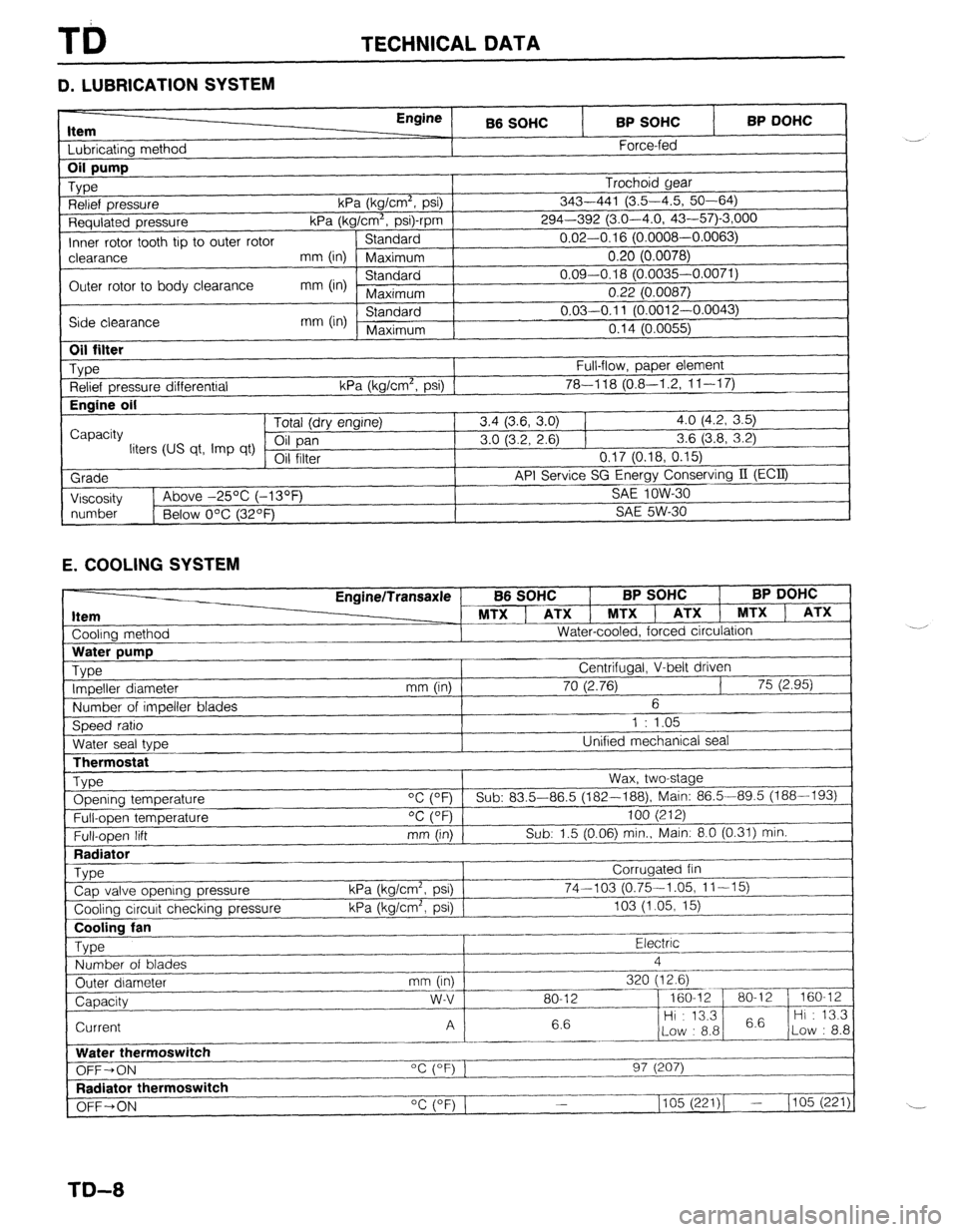
TECHNICAL DATA
D. LUBRICATION SYSTEM
Item I I bhricatinn mothnd
Engine
B6 SOHC BP SOHC
Force-fed BP DOHC 1
Requlated pressure kPa (kg/Cm”, p
Inner rotor tooth tip to outer rotor Standard
I-‘---- -.----,
clearance mm (in) Maximum 0.20 (0.0078)
Outer rotor to body clearance mm (in) Standard 0.09-0.18 (0.0035-0.0071)
Maximum 0.22 (0.0087)
Side clearance mm (in) Standard 0.03-0.11 (O.pniq n nnn=’
Maximum n4rl ‘-
“” I r-“.““+..I,
I “. I ‘t (U.0055)
I
1
Oil filter
_ Type
Relief pressure differential
Engine oil
I
Capacity
liters (US qt, Imp qt)
Grade
I Viscosity Full-flow, paper element
kPa (kg/cm’, psi) 1 78-l 18 (0.8-I .2, 1 l-l 7) Tntal /An, nnr*inol 3.4 (3.6, 3.0) 1 4.0 (4.2, 3.5)
3.0 (3.2, 2.6) 1 3.6 (3.8, 3.2)
VII 111Lb1 0.17 (0.18, 0.15)
API Service SG Energy Conserving II (ECQ
1
SA!f InW-Xl 1~ Above -25% (-13OF _ .-.. --
I
I
number
1 Below O’C (32OF) SAE 5W-30
1
E. COOLING SYSTEM
Cooling method EnginelTransaxle
MTX ] ATX 1 MTXl
Water-cooled, forced circulation
J B6 SOHC BP SOHC BP DOHC
, ATX 1 MTX ) ATX
LThermostat
Type Opening temperature
Full-open temperature
Full-open lift
Radiator
_ Type
Cap valve opening pressure
Cooling circuit checking pressure Wax, two-stage
“C (OF) Sub: 83.5-86.5 (182--188), Main: 86.5-89.5 (188-193)
OC (OF) 100 (212)
mm (in) Sub: 1.5 (0.06) min., Main: 8.0 (0.31) min.
Corrugated fin
kPa (kg/cm2, psi) 74-103 (0.75-1.05, 11-15)
kPa (kg/cm’, psi) 103 (1.05, 15)
~..
Cooling fan
Type Electric .-
Number of blades 4
_.---- _I___-
Outer diameter mm (in) 320 (12.6)
--_ ~~-
Capacity w-v 80-12 - 160-12 80-l 2 160-12
6.6 Hi : 13.3
6.6 Hi : 13.3
Current A
Low : 8.8 Low : 8.8
_------ ._____
Water thermoswitch
“c (OF) 1
OFF-ON 97 (207)
I--.
Radiator thermoswitch
__-I____-
OFF+ON “C (OF) 1 1105 (221)( - (105 (221)
TD-8
Page 1023 of 1164
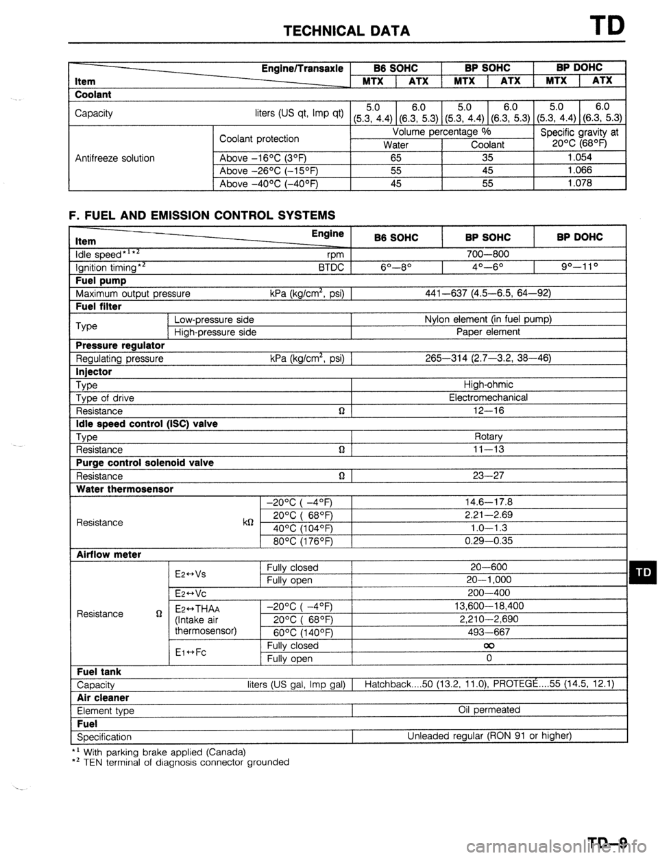
TECHNICAL DATA TD
Item
Coolant Engine/Transaxle B6 SOHC BP SOHC BP DOHC
MTX 1 ATX 1 MTX 1 ATX 1 MTX 1 ATX
Capacity
liters tus qt, Imp qt) (5Z.4) (8.E.3) (5&4) (SE.3) (5.?i.4) (S.E.3)
Coolant protection Volume percentage %
Specific gravity at
Water Coolant 20% (68OF)
Antifreeze solution Above -16OC (3OF)
65 35 1.054
Above -26OC (-15OF) 55 45 1.066
I Above -4OOC (-40°F) 45 55
1.078
F. FUEL AND EMISSION CONTROL SYSTEMS Item
idle speed*‘**
Ignition timing** Fuel pump
Maximum output pressure Fuel filter Engine
B6 SOHC BP SOHC BP DOHC
vm 700-800
BTDC 6O--8O 4O---6O 90-l 10
kPa (kg/cm*, psi) 1 441-637 (4.5-6.5, 64-92) ‘Type
Low-pressure side Nylon element (in fuel pump)
High-pressure side Paper element Pressure regulator
Regulating pressure kPa (kg/cm*, psi) 1 265-314 (2.7-3.2, 38-46) Injector
Type
High-ohmic
Type of drive Electromechanical
Resistance n 12-16 Idle speed control (ISC) valve
Type
Rotary
Resistance n ] 11-13 Purge control solenoid valve
Resistance n 1 23-27 Water thermosensor
-20°C( -4OF) 14.6-17.8
Resistance k6 20°C( 68QF) 2.21-2.69
40% (104OF) 1.0-l .3
80°C(1760F) 0.29-0.35 Airflow meter
E2++Vs Fully closed 20-600 q D Fully open 20-l ,000
E~HVC 200-400
Resistance g Ez++THAA -2O%(-4OF) 13,600-18,400
(Intake air 20%( 68OF) 2,210-2,690
thermosensor)
60°C(1400F) 493-667
Eic*Fc Fully closed 00
Fully open 0 Fuel tank
Capacity liters (US gal, Imp gal) I
Hatchback 50 (13.2, 11.0) PROTEGE . . . . 55 (14.5, 12.1) Air cleaner
Element type Oil permeated Fuel
Specification Unleaded regular (RON 91 or higher)
*’ With parking brake applied (Canada)
*’ TEN terminal of diagnosis connector grounded
TD-9
Page 1024 of 1164
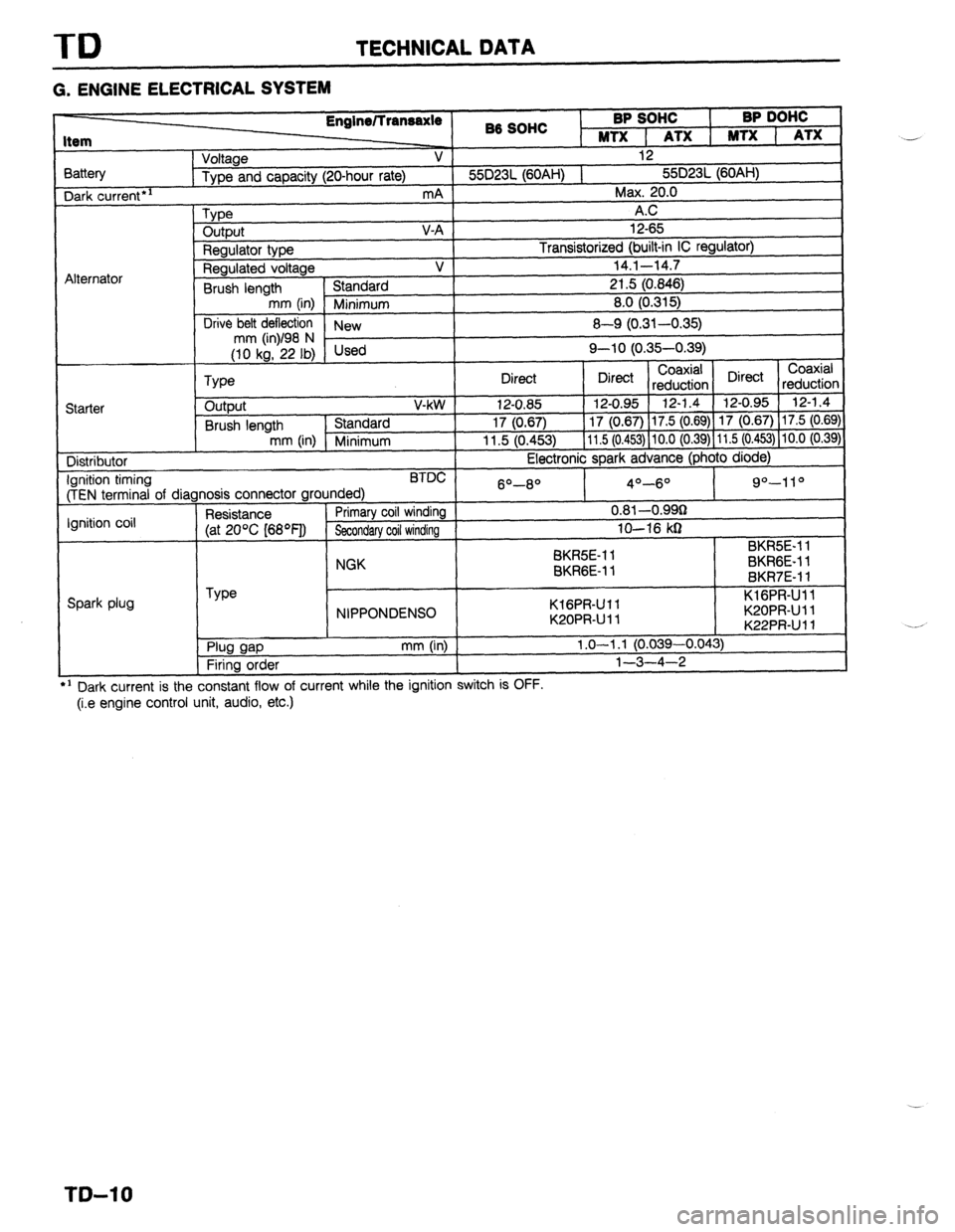
TD TECHNICAL DATA
G. ENGINE ELECTRICAL SYSTEM
3attery Dark
current*’
Alternator 86 SOHC BP SOHC
I BP DOHC
MTX 1 ATX 1 MTX 1 ATX
Voltage V 12
Type and capacity (20-hour rate) 55D23L (60AH) 1 55D23L (60AH)
mA Max. 20.0
Type A.C
output V-A 12-65
Regulator type Transistorized (built-in IC regulator)
Regulated voltage V 14.1-14.7
Brush length Standard 21.5 (0.846)
mm (in) Minimum 8.0 (0.315)
Drive belt deflection
New 8-Q (0.31-0.35)
;riL’F,i Used Q-10 (0.35-0.39)
Coaxial
Type Direct Direct Coaxial
reduction Direct
reductior
Starter output V-kW 12-0.85 12-0.95 12-1.4 12-0.95 12-1.4
Brush length Standard 17 (0.67) 17 (0.67) 17.5 (0.69) 17 (0.67) 17.5 (0.69
mm (in) Minimum 11.5 (0.453) 11.5 (0.453) 10.0 (0.39) 11.5 (0.453) 10.0 (0.39
Distributor Electronic spark advance (photo diode)
Ignition timing BTDC
(TEN terminal of diagnosis connector grounded) 6O-8O 4O-6O 9”-11 O
Ignition coil Resistance Primary coil winding 0.81 -O.QQg
(at 20% [68OF]) Secondary coil winding lo-16 kg
SK&E-1 1 BKR5E-11
NGK
BKRGE-11 BKRGE-11
BKR7E-11
Spark plug Type
NIPPONDENSO KlGPR-Ull
K20PRUll KlGPR-Ull
K20PRUll
K22PRUll *:
. Plug gap
Firing order mm (in) 1.0-l .l (0.039-0.043)
l-3-4-2
---
’ Dark current is the constant flow of current while the ignition switch IS UFF.
(i.e engine control unit, audio, etc.) ..-
._*
T&l 0
Page 1026 of 1164
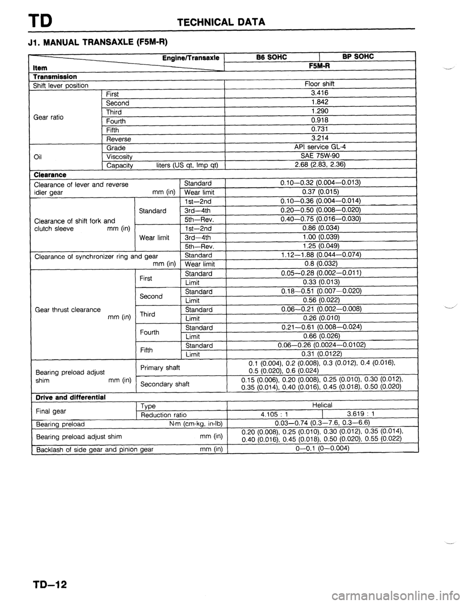
TD TECHNICAL DATA
Jl l MANUAL TRANSAXLE (FSM-R)
BB SOHC
l- BP SOHC I
F %M.R
I
1
Floor shift Item
Transmission Shift lever oosition Engine/lransaxle
First
Second
-I?-:-.4
I 0.918
I
n ‘31
I Gear ratio lllll”
Fourth
Fifth
Reverse
Grade
Oil Viscosity
Capacity liters (US qt, Imp qt) Clearance
Clearance of lever and reverse Standard
idler gear
mm (in) Wear limit
1 st-2nd
Standard 3rd-4th
Clearance of shift fork and Sth-Rev.
clutch sleeve mm (in)
1 st-2nd
Wear limit 3rd-4th
I 5th~Rev. j
Clearance of synchronizer ring and gear Standard ) mm (in)
Wear limit 3.416
1.842
1.290
ce GL-4
SW-90
I
V.I.
3.214
API servil
SAE 7t
2.68 (2.83, 2.36)
0.1 O-O.32 (0.004-o.
0.37 (0.015)
0.1 O-O.36 (0.004-o.
0.20-0.50 (0.008-O.
0.40-0.75 (0.016-O.
0.86 (0.034)
1 .oo (0.039)
i 3c /n n/la
I .L” \“.“T”,
1.12-l .88 (0,044-O.
0.8 (0.032)
0.05-0.28 (0.002-0.011)
0.33 (0.013)
0.18-0.51 (0.007-0.020)
0.56 (0.022)
0.06-0.21 (0.002-0.008)
0.26 (0.010)
0.21-0.61 (0.008-0.024)
0.66 (0.026)
0.06-0.26 (0.0024-0.0102)
0.31 (0.0122)
(0.008), 0.3 (0.012), 0.4 (0.016) Fifth Standard
Limit
0.1 (0.004) 0.2
Rnnrinn nrdnari adjust Primary shaft
0.5 (0.020) 0.6
I shim mm (in)
Secondary shaft 0.15 (0.006) 0.20 (0.008) 0.25 (0.
~-~?r;liln
I Final gear
Bearing preload
I Bearing preload adjust shim
[Backlash of side gear and pinion gear
I
I
030)
,074)
I
First Standard
Limit
Second Standard
Limit
Gear thrust clearance
mm (in) Third Standard
Limit
Fourth Standard
Limit
(0.024j
OlO), 0.30 (0.012)
I
I V.“” \“‘V I .,, “.~lV \Y... VW,? “I ,-
\... 018j, 0.50 (0.020)
Helical
4.105 : 1
I 3.619 : 1
N,m (cm-kg, in-lb) 0.03-0.74 (0.3-7.6, 0.3-6.6)
n qn
mm (in)
“.L” ,“.“U mnr78), 0.25 (o.oio), 0.30 (0.012) 0.35
(0.014)
0.40 (0.01 6) 0.45 (0.018),
0.50 (0.020) 0.55 (0.022)
-~ -1
mm (in) j o-o.1 (O-0.004 --
--’
TD-12
Page 1031 of 1164
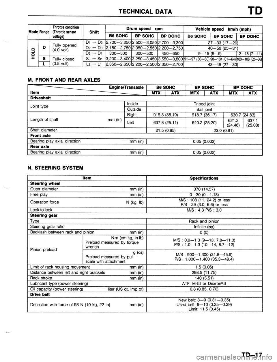
TECHNICAL DATA TD
1 Throttle condition 1
nrllm pn-t
Mode Rr _ me/ flhrottle sensor 1 Shift 1 -.- -*r2d rpm
Vehicle speed I km/h (mohl , . ,
I
ioltage) 1 B6 sot
iC 1 BP SOHC 1 BP DOHC
66 SOHC 1 BP SOHC 1 BP
I I I
’ ni - n9 I’) 7nn-1 “50 2,500-3,05012,700-3.3001 I I DOHC
Fully opened 27-33 (17-201
3 D (4.0 volt) 50 2,050-2,55012,200-2,750]
40-50 i25-31 j
e I 300-500 1 450-650 / Q-15 16-9) 112-18 (7-111
00 3,250-3,45013,550-3.800~91-97 f56-60&G10’4 (61-64)hOO-106;62-&\I
s
i- f Fully closed
(0.5 volt)
YI -l&c
L, r vv-“,L
Dz + D3 2,150-2,7
D3 -+ DI 300--5O(
S3 -+ S2 3,200-3,4
’ L2 -+ LI 2,350-2,65012,200-2,50012,350-2.7001
43-49 ;27--3b1 ’ ‘I
M. FRONT AND REAR AXLES -
Item
Driveshaft Engine/Transaxle BP SOHC BP DOHC
Joint type
Length of shaft
Shaft diameter Front axle
Bearing play axial direction Rear axle
Bearing play axial direction Inside Tripod joint
Outside Ball joint
Right
919.3 (36.19) 918.7 (36.17) 630.7 (24.83)
mm (in) Left
637.8 (25.11) 640.2 (25.20) 621.2
637.1
(24.46) (25.08)
21.5 (0.85) 23.0 (0.91)
mm (in) 1 0.05 (0.002)
mm (in) I 0.05 (0.002)
N. STEERING SYSTEM Steering wheel
Outer diameter Item Specifications 370 (14.57)
Lock-to-lock I Steering gear
--
Type
Steering gear ratio
Backlash between rack and pinion mm (in)
N.r ’ ’ ” ’ n (cm-Kg, in-01
Preload measured by torque
*rrv~rrdl Rack and pinion
Infinite (00)
0 (0)
M/S : 0.9-l .3 (Q-13, 7.8-l 1.3)
P/S : 1.0-1.3 (10-14, 8.7-12)
Pinion preload ““l~jll~,,
9 (0.4
Preload measured by pull
scale with attachment
Limit of rack housing movement mm (in)
Distance between left and right brackets mm (in)
Rack stroke mm (in M/S : 900-l ,300 (31.8-45.9)
P/S : l,OOO-1,400 (35.3-49.4)
1.5 (0.06)
298.5 (11.75)
140 (5.511
Lubricant type (power steering)
Oil capacity (power steering) Drive belt
liter (US qt, Imp qt) I ATF: M-III or DexronW
0.8 (0.85, 0.70)
I New belt: 8-Q (0.31-0.35)
Deflection with force of 98 N (10 kg, 22 lb) mm (in) Used belt: 9-10 (0.35-0.39)
I imit: 11.5 (0.461
TD-17