1992 MAZDA PROTEGE brake
[x] Cancel search: brakePage 942 of 1164

I
CRUISE CONTROL SYSTEM
s q 0 m
9 e c a
t rpn i j
h
f d b
*
Inspection
Cruise control unit
1. Connect a voltmeter between cruise control unit and ground.
2. Turn the ignition switch ON and check the terminal voltages
as described below.
03UOTX-146
VB: Batterv voltage
c (Output) Actuator
I ov
Approx. 9V
e (Input)
I Cruise control main
I
VB switch (NC)
f (Input)
9 Wv-4 Cruise control main
switch (N.0)
EC-AT control unit
VB
V0
h (Output) (only ATX)
Stoplight switch 2 (N.C) Approx. 9V
i (hW Note I
Inhibitor switch (ATX)
I ov
Approx. 5V Disconnect t
EGI control
Clutch switch (MTX)
ov unit connector Approx. 5V
Cruise control switch
(Set/coast switch) V0
Approx. 5V unit connector
a
S I Battery
I VI3 t
1 Ground I ov Procedure
Ignition switch ON
Main switch ON
Ignition switch ON
Main switch ON
ignition switch ON
Main switch ON
Ignition switch ON
Main switch ON
Ignition switch ON
Main switch ON
“N” or “P” range and main switch ON
Other range and main switch ON
Clutch pedal depressed and main switch ON
Main switch ON
Horn switch OFF
Ignition switch ON
Brake pedal depressed
Main switch ON
While pushing the resumelaccel switch after main switch
ON
Main switch ON
While pushing the set/coast switch after main switch ON
Main switch ON
Brake pedal depressed
While rotating the rear tire
Constant
Constant
23UOTX-OE $0
‘,.__,
_ _-_,’
T-86
Page 943 of 1164

CRUISE CONTROL SYSTEM T
OSUOTX-14
PEDAL HEIGHT
03UOTX-I 4’
OSUOTX-18
Actuator
Measure the actuator solenoid resistance using an ohmmeter.
Check terminals
c-a
c-b Resistance
Approx. 22 to 553
Clutch switch, Brake switch
When servicing these switches, adjust them so that the cor-
responding pedal height is as specified.
Pedal height (With carpet)
Clutch: 196-204mm (7.72--6.03 in)
Brake : 193-196mm (7.60-7.72 in)
Stoplight switch (For cruise)
Check that there is continuity between (P) and (V) wires when
the brake pedal is released.
T-87
Page 1023 of 1164
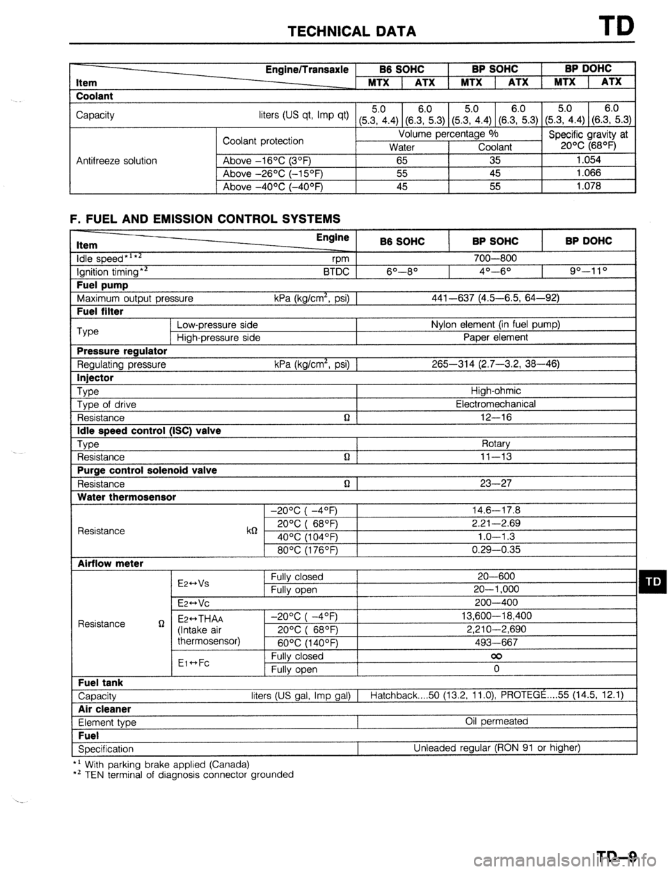
TECHNICAL DATA TD
Item
Coolant Engine/Transaxle B6 SOHC BP SOHC BP DOHC
MTX 1 ATX 1 MTX 1 ATX 1 MTX 1 ATX
Capacity
liters tus qt, Imp qt) (5Z.4) (8.E.3) (5&4) (SE.3) (5.?i.4) (S.E.3)
Coolant protection Volume percentage %
Specific gravity at
Water Coolant 20% (68OF)
Antifreeze solution Above -16OC (3OF)
65 35 1.054
Above -26OC (-15OF) 55 45 1.066
I Above -4OOC (-40°F) 45 55
1.078
F. FUEL AND EMISSION CONTROL SYSTEMS Item
idle speed*‘**
Ignition timing** Fuel pump
Maximum output pressure Fuel filter Engine
B6 SOHC BP SOHC BP DOHC
vm 700-800
BTDC 6O--8O 4O---6O 90-l 10
kPa (kg/cm*, psi) 1 441-637 (4.5-6.5, 64-92) ‘Type
Low-pressure side Nylon element (in fuel pump)
High-pressure side Paper element Pressure regulator
Regulating pressure kPa (kg/cm*, psi) 1 265-314 (2.7-3.2, 38-46) Injector
Type
High-ohmic
Type of drive Electromechanical
Resistance n 12-16 Idle speed control (ISC) valve
Type
Rotary
Resistance n ] 11-13 Purge control solenoid valve
Resistance n 1 23-27 Water thermosensor
-20°C( -4OF) 14.6-17.8
Resistance k6 20°C( 68QF) 2.21-2.69
40% (104OF) 1.0-l .3
80°C(1760F) 0.29-0.35 Airflow meter
E2++Vs Fully closed 20-600 q D Fully open 20-l ,000
E~HVC 200-400
Resistance g Ez++THAA -2O%(-4OF) 13,600-18,400
(Intake air 20%( 68OF) 2,210-2,690
thermosensor)
60°C(1400F) 493-667
Eic*Fc Fully closed 00
Fully open 0 Fuel tank
Capacity liters (US gal, Imp gal) I
Hatchback 50 (13.2, 11.0) PROTEGE . . . . 55 (14.5, 12.1) Air cleaner
Element type Oil permeated Fuel
Specification Unleaded regular (RON 91 or higher)
*’ With parking brake applied (Canada)
*’ TEN terminal of diagnosis connector grounded
TD-9
Page 1028 of 1164
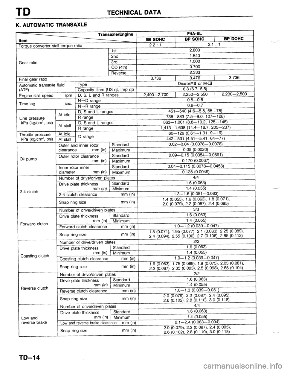
TD TECHNICAL DATA
K. AUTOMATIC TRANSAXLE
TransaxlelEngine F4A-EL
Item
66 SOHC
I BP SOHC
I BP DOHC Torque converter stall torque ratio
2.2 : 1
2.1 : 1
I 1st
2.800
Gear ratio .-.
2nd
1.540
3rd 1 .ooo
nn /“a..
n 7nn
I f-8 ^. .^ _^^ I
3 ,a?? I
Engine stall speed rpm D, S, L and A
Time lag -iOf I 7 Ann-3 7nn
I 7 7.513-7 550 I ran+ L,7”” +,I “V , -,--- . . ..--- , ,,200-2,500
0.5-0.6
, .
I 0.6-0.7
( D, S and L ranges
~-t- -r” I
&L :-I,- “7” \T.” V.“, “i)---,a,
nr IUlt:
I k :^^ -I ^^^.._^ Llllt: p,txis”ra R range 736---c-- . 983 17.5-9.0, 107-l 28)
I l/PI Ilsnlrm2 nci 1\1 u \‘.y,Y”’ , y-8, I n c lrw-4 I *n”nPc Y, ” UI I” L I UI ‘yvu I I FWA-1 no1 ma- ---
At stall ,_ - \-._ -10.2, 125-145)
R range I,41 3-1,638 (14.4-l 6.7, 205-237)
At idle 60-129 (0.61-1.31, 9-19)
At stall D range
I All.3 E?, ,A E,
Outer and inner rotor Standard “.“_ “... \-.-... - -v.vvru,
clearance
mm (in) Maximum
I n n!i (I7 nn7rv
.,.-- - . _ - - -,
Outer rotor clearance Standard n no-n 1.5 m mid- n n=m Y,YY “. * - \~ .--- -v.v.Jil I)
mm (in) Maximum 0.170 (0.0067)
Inner rotor inner Standard 0.04-0.115 (0.0078-0.0453)
diameter
mm (in) Maximum 0.125 (0.0049)
Number of drive/driven plates 414 I
Lt-+c---,,c) , \-t.d , -5.41, 64-77)
n n7-n n4 fn nn78- n finTQ
I I
T I Throttle pressure
kPa (kg/cm2, psi)
Oil pump
3-4 clutch
I Drive plate thickness 1.6 (0.063)
. ..I.. \‘..I , ,“,III,IIIUI,I
3-4 clutch clearance mm (in) 1.4 (0.055)
1.3-l .6 (0.051-0.063)
’ A ‘Ant==’ ’ C ‘“.063), 1.8 (0.071).
I Snan rim-7 ciza
mm fin I I.-t \“.“Qd,, I.” \”
^ ^ ,^ ^_... ,. ,. I,. “1 ,-I-’ I II ,y VI+...
.““’ \‘..I z.u (UUIY), z.z (U.O87j, 2.4 (0.095j.
1 Number of drive/driven plates
I 313
1.6 (0.063)
Drive plate thickness 1 Standard
mm (in) Minimum
Forward clutch clearance mm (in) ,
1.0-I .2 (0.039-n ’ 1.4 io.05si
I
“.347)
(0.071) 1.95 (0.07;), 2.1 (0.083) 2.25 (0.089)
I--’ ^^_ ,^ .,^
Snap ring size mm (in) 1.8 I
2.4
(u.uY~), L.CCJ (u. IUU), L.I
Number of drive/driven plates 2/z
Drive plate thickness Standard 1.6 (0.063)
mm (in) Minimum 1.4 (0.055)
Coasting clutch clearance mm (in) 1.0-l .2 (0.039-0.047)
4 c In Yj3), 1.75 (0.069), 1.9 (0.075) 2.05 (0.081)
.
L.C (u.u87), 2.35 (0.093) 2.5 (0.098), 2.65 (0.104)
1 Number of drive/driven plates I
2/z
1.6 (0.063) Forward clutch
Coasting clutch
IS nao rina size
Drive plate thickness Standard
I
mm (in) Minimu
Reverse clutch clearance mm (in) 1.0-l .3 (0.031
Snap ring size mm (in) 2.0 (0.079), 2.
2.6 (0.102) 2.” ,v., ,v,, J.V \v. g
Number of drive/driven elates 414
m- I i .4 io.055j
3-0.051)
2 (0.087) 2.4 (0.095),
cth3i1n Qn~n*~o
-=----I
Reverse clutch t
1 Drive plate thickness 1 Standard 1 1.6 (0.063)
mm (in) 1 Minimum 1.4 (0.055)
Low and reverse brake clearance mm (in) 2.1-2.4 (0.08: 3-0.094)
I
2.0
(0.079), 2.2 (0.087) 2.4 (0.095)
I I 2.6 (0.102), 2.8 (0.110)
3.0 (0.118) Snap ring size mm (in) 1 Low and
reverse brake
TO-I 4
Page 1030 of 1164
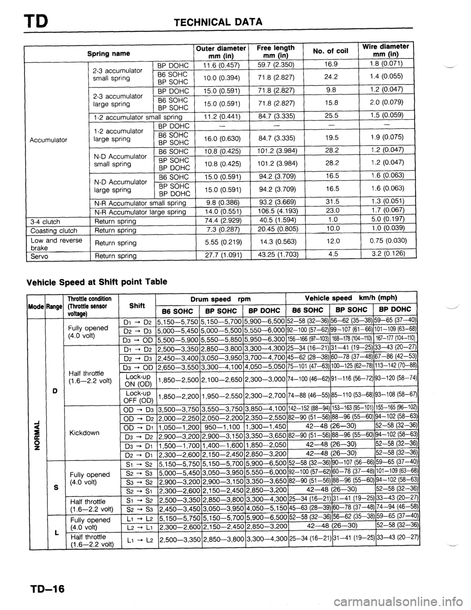
TD TECHNICAL DATA
Spring name
2-3 accumulator
small spring Outer diameter Free length Wire diameter
mm (in) mm (in) No. of coil
mm (in) BP DOHC 11.6 (0.457)
59.7 (2.350)
16.9 1.8 (0.071)
56 SOHC
BP SOHC 10.0 (0.394) 71.8
(2.827) 24.2 1.4 (0.055)
2-3 accumulator BP DOHC 15.0
(0.591) 71.8 (2.827) 9.8
1.2 (0.047)
large spring B6 SOHC
BP SOHC 15.0 (0.591)
71.8 (2.827)
15.8 2.0 (0.079)
l-2 accumulator small spring
11.2 (0.441)
84.7 (3.335)
25.5 1.5 (0.059)
BP DOHC
- - -
-
l-2 accumulator
Accumulator large spring B6 SOHC
BP SOHC 16.0 (0.630)
84.7 (3.335) 19.5
1.9 (0.075)
B6 SOHC 10.8 (0.425) 101.2 (3.984)
28.2
1.2 (0.047)
N-D Accumulator
small spring BP SOHC
BP DOHC
10.8 (0.425) 101.2 (3.984)
28.2
1.2 (0.047)
B6 SOHC
15.0 (0.591) 94.2 (3.709)
16.5
1.6 (0.063)
N-D Accumulator
large spring BP SOHC
BP DOHC 15.0 (0.591) 94.2
(3.709) 16.5
1.6 (0.063)
N-R Accumulator small spring
9.8 (0.386)
93.2 (3.669) 31.5
1.3 (0.051)
N-R Accumulator large spring
14.0 (0.551) 106.5 (4.193)
23.0 1.7 (0.067)
3-4 clutch
Return spring
74.4 (2.929)
40.5 (1.594) 1 .o
5.0 (0.197)
Coasting clutch
Return spring
7.3 (0.287) 20.45 (0.805)
10.0 1 .o (0.039)
Low and reverse
brake Return
spring 5.55 (0.219)
14.3 (0.563)
12.0 0.75 (0.030)
Servo
Return spring
27.7 (1.091) 43.25 (1.703)
4.5
3.2 (0.126)
Vehicle Speed at Shift point Table -
lode
- -
angc
-
D Throttle condition
(Throttle sensor
voltage)
Fully opened
(4.0 volt)
Half throttle
(1.6-2.2 volt)
/ &%L) j 3 1 850-2,500 2,100-2,650 2,300-3,000 74-100 (46-62) 91-116 (56-72) 93-120 (58-74
Lock-up
[1,850-2,20011,950-2.550(2,300-2,700/74-88 (46--55)185-110 (53-68)(93-108 (58-67)1
Kir.kdnwn OD -+ DI
1,05U
%lly opened
i4.0 volt)
Half throttle
s2 -+ s3 5,000-5,45c
s3 -+ s2 2,900
S2 -+ ST 2,300-2,6OC
SI * 52
2.500-3.35C
(1.6-2.2 volt)
s2 -+ s3 v, v...
Fully opened Ll + L2 5,150-5,75(
w-dt I7w-ln
nlf throttle 6-7 7 vnltl I Ll + L2 (2.500-3.350(2,850-3,8OOj3.300-4.300125-34 (16-21$1-41 (19-25)j33-43 (20-27)1
TD-16
Page 1032 of 1164
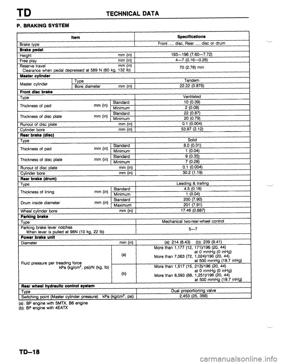
TD TECHNICAL DATA
P. BRAKING SYSTEM
Item
3rake type
Brake pedal
Height mm (in)
Free play mm (in)
Reserve travel mm (in)
Clearance when pedal depressed at 589 N (60 kg, 132 lb)
Master cylinder
Type
Master cylinder
Bore diameter mm (in) 1
Front disc brake
We
Thickness of pad
mm (in) Standard
Minimum
Thickness of disc plate
mm (in) Standard
Minimum
Runout of disc plate mm (in)
Cylinder bore
mm (in) Specifications
Front . . . . . disc, Rear . . . . . disc or drum
193-196 (7.60-7.72)
4-7 (0.16-0.28)
70 (2.76) min
Tandem
22.22 (0.875)
Ventilated
10 (0.39)
2 (0.08)
22 (0.87)
20 (0.79)
0.1 (0.004)
53.97 (2.12)
Rear brake (drum)
We
Thickness of lining
I Drum inside diameter
1
tiheel cylinder bore
I Parking brake
Type
Parking brake lever notches Leading & trailing
mm (in) Standard 4.5 (0.18)
Minimum 1 (0.04)
mm (in) Standard 200 (7.90)
Maximum 201 (7.91)
mm (in) 17.46 (0.687)
Mechanical two-rear-wheel control
When lever is pulled at 98N (10 kg, 22 lb)
Power brake unit
Diameter mm (in) 5-7
(a): 214 (8.43) (b): 239 (9.41)
More than 1,177 (12, 171)/196 (20, 44)
Fluid pressure per treading force
kPa (kg/cm’, psi)/N (kg, lb) (4
@I at 0 mmHg (0 inHg)
More than 7,063 (72, 1,024)/l 96 (20, 44)
at 500 mmHg (19.7 inHg)
More than 1,517 (15, 213)/196 (20, 44)
at 0 mmHg (0 inHg)
More than 8,593 (88, 1,261)/196 (20, 44)
at 500 mmHg (19.7 inHg)
Rear wheel hydraulic control rystem
Type Dual proportioning valve
_-_.
. .- ,. . . . !
P.IF
Switching point (Master cylinder pressure)
KPa (kg/cm-, PSI) ) z,4~j3 (25, 356)
(a): BP engine with SMTX, B6 engine
(b): BP engine with 4EATX ..-
-’
TD-18
Page 1034 of 1164
TD TECHNICAL DATA
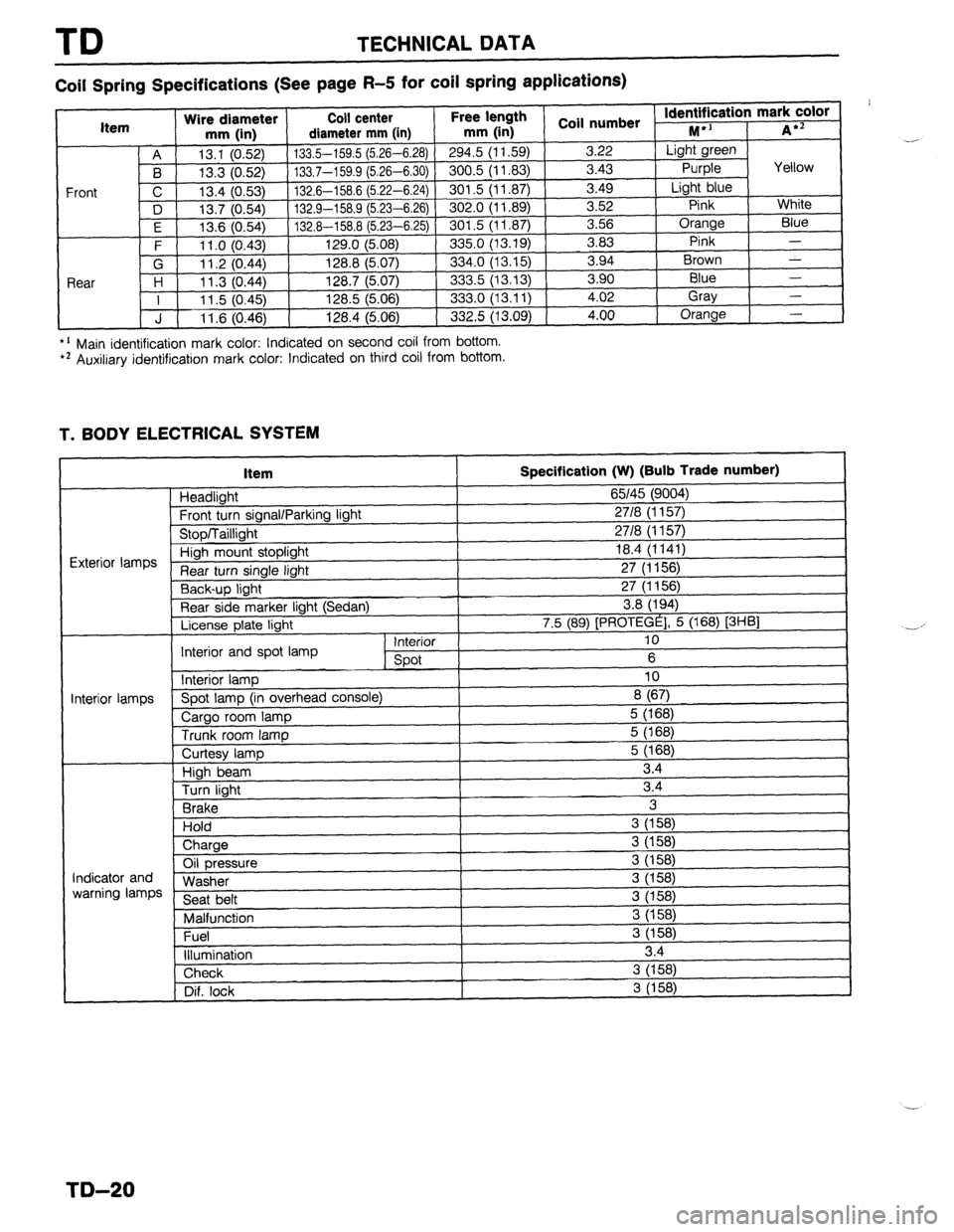
Coil Spring Specifications (See page R-5 for coil spring applications)
*’ Main identification mark color: Indicated on second coil from bottom. l * Auxiliary identification mark color: Indicated on third coil from bottom.
T. BODY ELECTRICAL SYSTEM
Item
Headlight
Frnnt tl wn sinnnl/Pnrkinn linht
Specification (W) (Bulb Trade number)
65145 (9004)
2718 II I 571
I
“‘VW, I u”“y’ 1. I” \’ ‘V’,
uinh mount stoplight 18.4 (1141)
turn single light 27 (1156)
Y-,-~p light 27 (1156)
Rear side marker light (Sedan) 3.8 (194)
License plate light 7.5 (89) [PROTEGE], 5 (168) [3HBl
Interior 10
Interior and spot lamp
spot 6
Interior lamp 10
‘i--” Spot lamp (in overhead console)
8 (67)
Cargo room lamp 5 (168)
Trunk room lamp 5 (168)
I I
ntminr Iamnc
I
Curtesy lamp
High beam
Turn light
Brake
Hold
) Charge 5 (168)
3.4
3.4
3
3 (158)
i
Oil pressure
Washer
Seat belt
Malfunction
Fuel
illumination 3 (158)
3 (158)
3 (158)
3 (158)
3 (158)
3 (158)
3.4 Indicator and
warning lamps
Check 3 (158)
Dif. lock
I 3 (158) .-
,
-.-’
I
I
TD-20
Page 1045 of 1164
SPECIAL TOOLS ST
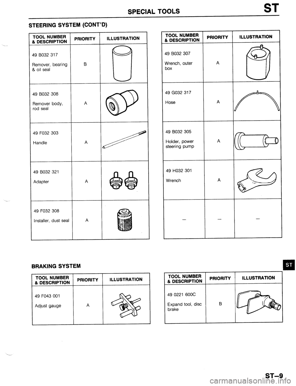
STEERING SYSTEM (CONT’D)
PRIORITY ILLUSTRATION I-OOL NUMBER
i DESCRIPTION PRIORITY ILLUSTRATION 1OOL NUMBER
h DESCRIPTION
-9 8032 307
19 8032 317
A
Yrench, outer
)0X ?emover, bearing
1 oil seal
19 GO32 317
-lose 19 B032 308
qemover body,
,od seal
49 F032 303 $9 8032 305
iolder, power
steering pump Handle A
A 49 HO32 301
Wrench A 49 B032 321
Adapter . .
49 F032 308
Installer. dust seal A - -
-
BRAKING SYSTEM
TOOL NUMBER
PRIORITY ILLUSTRATION TOOL NUMBER
& DESCRIPTION PRIORITY ILLUSTRATION
& DESCRIPTION
49 F043 001
Adjust gauge A 49 0221 600C
Expand tool, disc B
brake
ST-9