Page 1010 of 1164
AIR CONDITIONER
REFRIGERANT LINES
On-vehicle Inspection
Check for leakage at connections. (Refer to page U-32.)
Repair or replace as necessary.
Replacement
1. Discharge the refrigeration system. (Refer to page U-32.)
2. Replace the faulty pipe or hose.
Note
l Immediately plug the open fittings to keep moisture out of the system.
l Apply clean compressor oil to the O-rings before connecting the fittings.
l Do not apply compressor oil to the fitting nuts.
Tightening torque (fittings):
Location Tightening torque
0 9.8-20 N.m
(1.0-2.0 m-kg, 7.2-14 ft-lb)
0 15-25 N-m (1.5-2.5 m-kg, 11-18 ft-lb)
0 9.8-16 N.m (1.0-1.6 m-kg, 7.2-12 ft-lb)
fa 20-29 N.m
(2.0-3.0 m-ka 15-21 ft-lb)
3. Evacuate, charge, and test the refrigeration system.
1. High-pressure hose
2. Low-pressure hose
3. Cooler pipe No.1 4. Cooler pipe No.2 6. Cooler pipe No.4
5. Cooler
pipe No.3 7. Cooler pipe No.5
u-54
Page 1011 of 1164

AIR CONDITIONER U
REFRIGERANT PRESSURE
2.0 f 0.2 kg/cm* 27 f 2 kg/cm’
4.1 f 0.5 kg/cm* 21 * 4 kg/cm*
03uoux-09
9
23UOUX-050
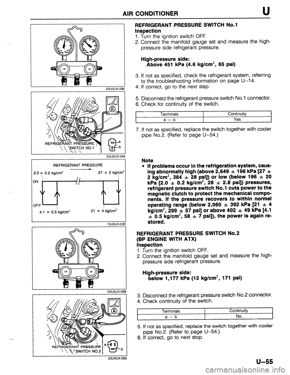
REFRIGERANT PRESSURE SWITCH No.1
Inspection
1. Turn the ignition switch OFF.
2. Connect the manifold gauge set and measure the high-
pressure side refrigerant pressure.
High-pressure side:
Above 451 kPa (4.6 kg/cm2, 65 psi)
3. If not as specified, check the refrigerant system, referring
to the troubleshooting information on page U-14.
4. If correct, go to the next step.
5. Disconnect the refrigerant pressure switch No.1 connector.
6. Check for continuity of the switch.
Terminals
1 Continuity
a-b
Yes I
7. If not as specified, replace the switch together with cooler
pipe No.2. (Refer to page U-54.)
Note
l If problems occur in the refrigeration system, caus-
ing abnormally high (above 2,649 SL: 196 kPa [27 f
2 kg/cm2, 384 f 28 PSI]) or low (below 196 f 20
kPa [2.0 f 0.2 kg/cm2, 28 & 2.8 psi]) pressures,
refrigerant pressure switch No.1 cuts power to the
magnetic clutch to protect the mechanical compo-
nents. If the pressure recovers to within normal
operating range (below 2,080 f 392 kPa [21 f 4
kg/cm2, 299 f 57 psi] or above 402 f. 49 kPa t4.1
f 0.5 kg/cm2, 58 f 7 psi]), the power is again re-
stored.
REFRIGERANT PRESSURE SWITCH No.2
(BP ENGINE WITH ATX)
Inspection
1. Turn the ignition switch OFF.
2. Connect the manifold gauge set and measure the high-
pressure side refrigerant pressure.
High-pressure side:
below 1,177 kPa (12 kg/cm2, 171 psi)
3. Disconnect the refrigerant pressure switch No.2 connector.
4. Check continuity of the switch.
Terminals
a-b I Continuity
No
5. If not as specified, replace the switch together with cooler
pipe No.2. (Refer to page U-54.)
6. If correct, go to next stop.
u-55
Page 1012 of 1164

AIR CONDITIONER
23UOUX-051
23UOUX-05
23UOUX-05
U-56
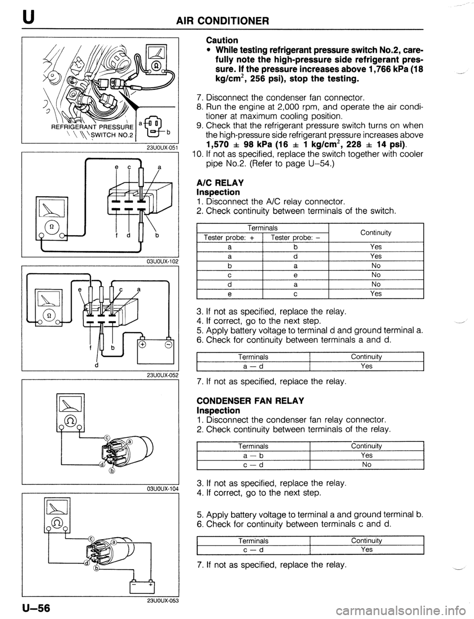
Caution
l While testing refrigerant pressure switch No.2, care-
fully note the high-pressure side refrigerant pres-
sure. If the pressure increases above 1,766 kPa (18
kg/cm2, 256 psi), stop the testing. _,
7. Disconnect the condenser fan connector.
8. Run the engine at 2,000 rpm, and operate the air condi-
tioner at maximum cooling position.
9. Check that the refrigerant pressure switch turns on when
the high-pressure side refrigerant pressure increases above
1,570 f 98 kPa (16 f 1 kg/cm2, 228 f 14 psi).
IO. If not as specified, replace the switch together with cooler
pipe No.2. (Refer to page U-54.)
A/C RELAY
Inspection
1. Disconnect the A/C relay connector.
2. Check continuity between terminals of the switch.
Terminals
Tester probe: + 1 Tester probe: -
a b Continuity
Yes
3. If not as specified, replace the relay.
4. If correct, go to the next step.
5. Apply battery voltage to terminal d and ground terminal a.
6. Check for continuity between terminals a and d.
Terminals
a-d Continuity
Yes
7. If not as specified, replace the relay.
CONDENSER FAN RELAY
Inspection
1. Disconnect the condenser fan relay connector.
2. Check continuity between terminals of the relay.
Terminals Continuity
I a-b Yes I
2
I c-d I No I
A 3. If not as specified, replace the relay.
4. If correct, go to the next step.
5. Apply battery voltage to terminal a and ground terminal b.
6. Check for continuity between terminals c and d.
Terminals Continuity
c-d Yes
7. If not as specified, replace the relay.
Page 1013 of 1164
AIR CONDITIONER U
CONDENSER FAN
Removal / Installation
1. Remove the radiator grille. (Refer to Section S.)
2. Disconnect the condenser fan connector.
3. Remove the bolts and remove the condenser fan.
4. Install in the reverse order of removal.
I 03uoux-106
I
23UOUX-05
I
r 23UOUX-OE
a
19
Inspection
1. Disconnect the condenser fan connector.
2. Apply battery voltage to terminal a and ground terminal b,
and verify that the condenser fan operates.
3. If not as specified, replace the condenser fan.
A/C SWITCH
Inspection
1. Remove the A/C switch and check continuity between ter-
minals.
0-O: Indicates continuity
G-k0 Indicates diode
2. If not as specified, replace the A/C switch.
u-57
Page 1015 of 1164

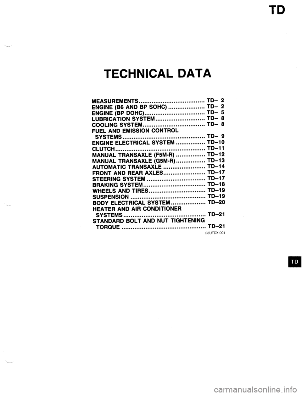
TD
TECHNICAL DATA
MEASUREMENTS .................................... TD- 2
ENGINE (B6 AND BP SOHC)
ENGINE (BP DOHC) ... .................................................. ;;- f
LUBRICATION SYSTEM ........................... TDI 6
COOLING SYSTEM .................................. TD- 6
FUEL AND EMISSION CONTROL
SYSTEMS ............................................. TD- 9
ENGINE ELECTRICAL SYSTEM ................ TD-10
CLUTCH ................................................. TD-11
MANUAL TRANSAXLE (F5M-R) ................ TD-12
MANUAL TRANSAXLE (GSM-R) ................ TD-13
AUTOMATIC TRANSAXLE ....................... TD-14
FRONT AND REAR AXLES.. .....................
STEERING SYSTEM ................................ ;;-;;
-
BRAKING SYSTEM .................................. TD-16
WHEELS AND TIRES ............................... TD-19
SUSPENSION ......................................... TD-19
BODY ELECTRICAL SYSTEM ................... TD-20
HEATER AND AIR CONDITIONER
SYSTEMS ............................................. TD-21
STANDARD BOLT AND NUT TIGHTENING
TORQUE .............................................. TD-21
23UTDX-001
Page 1035 of 1164

TECHNICAL DATA TD
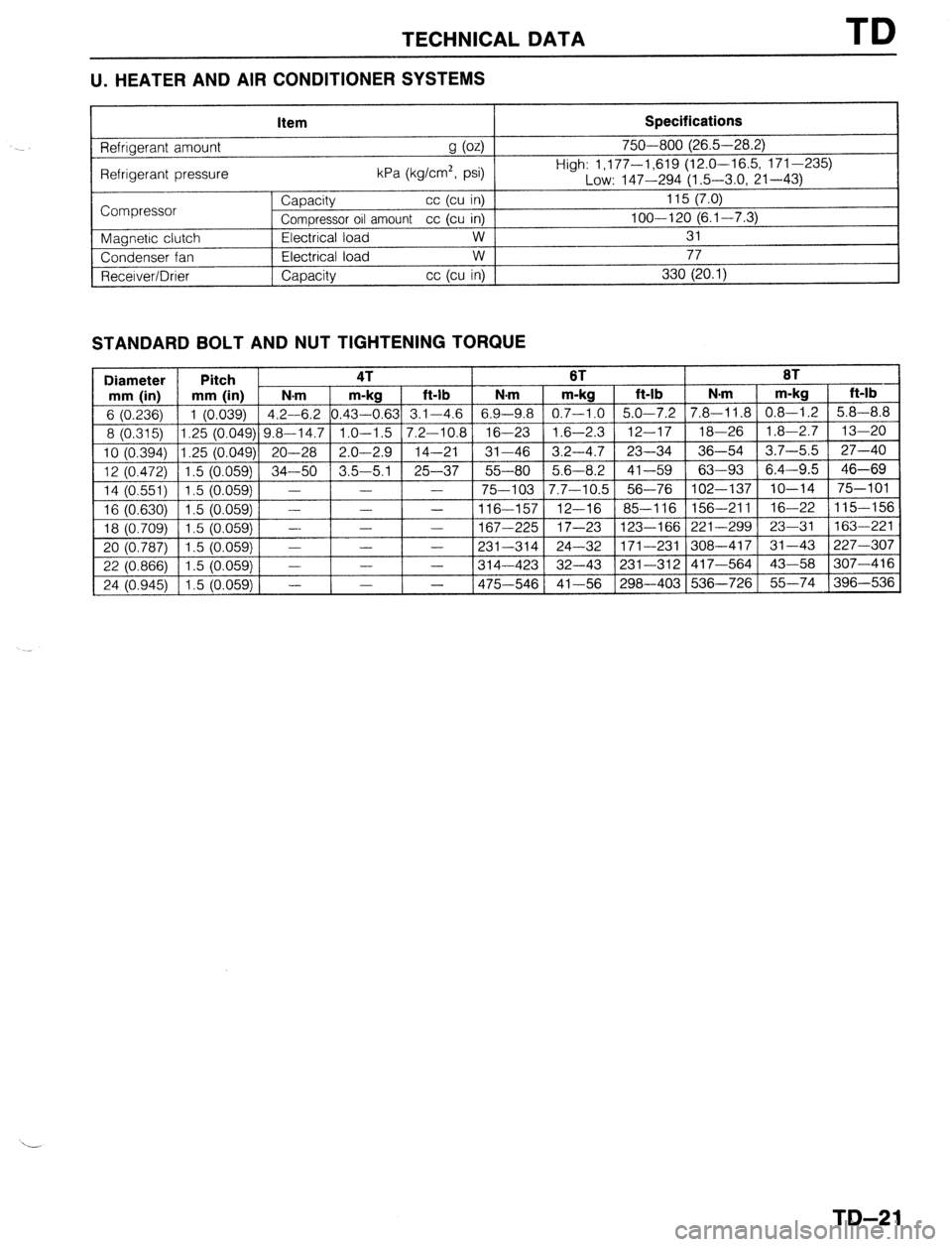
U. HEATER AND AIR CONDITIONER SYSTEMS
Item Specifications
Refrigerant amount
g (04
Refrigerant pressure kPa (kg/cm2, psi) 750-800 (26.5-28.2)
High: 1,177-1,619 (12.0-16.5, 171-235)
Low: 147-294 (1.5-3.0, 21-43)
Compressor
Magnetic clutch
Condenser fan
Recerver/Drier Capacity cc (cu in)
Compressor oil amount cc (cu in)
Electrical load w
Electrical load w
Capacity cc (cu in) 115 (7.0)
loo---120 (6.1-7.3)
31
77
330 (20.1)
STANDARD BOLT AND NUT TIGHTENING TORQUE
Diameter Pitch 4T 6T 8T
mm (in) mm (in) N-m m-kg ft-lb N.m m-kg ft-lb N.m m-kg ft-lb
6 (0.236) 1 (0.039) 4.2-6.2 0.43-0.63 3.1-4.6 6.9-9.8 0.7-1.0 5.0-7.2 7.8-11.8 0.8-1.2 5.8-8.8
8 (0.315) 1.25 (0.049) 9.8-14.7 1.0-1.5
7.2-10.8 16-23 1.6-2.3 12-17 18-26 1.8-2.7 13-20
10 (0.394) 1.25 (0.049) 20-28 2.0-2.9
14-21 31-46 3.2-4.7 23-34 36-54 3.7-5.5 27-40
12 (0.472) 1.5 (0.059) 34-50 3.5-5.1 25-37 55-80 5.6-8.2
41-59 63-93 6.4-9.5 46-69
14 (0,551) 1.5 (0.059)
- - - 75-103 7.7-10.5 56-76 102-137
lo-14 75-101
1 16 (0.630) 1 1.5 iO.059j 1 - 1 - - 116-157 12-16 85-116 156-211 16-22 115-156
1 18 ;0.709j Il.5 iO.O59 1 - 1 -
167
1 20 i0.787; Il.5 iO.059i 1 - 1 - 1 - 12:
31 _..
22 (0.866) 1 1.5 io.059j 1 - 1 - 1 - 1314-423 __ ._ ,--. -._,
1 I
24 (0.945) 1 1.5
(0.059) 1 -
- 1475-546 41-56 (298-4031536-7261 55-74 1396-536 -2251 17-23 123-166 221-299 23-31 163-221
-3141 24-32 171-231 308-417 31-43 227-307
37-43 331-312 417-564 43-58 307-416
TD-21
Page 1037 of 1164
SPECIAL TOOLS
GENERAL INFORMATION ........................
ENGINE .................................................. i;-
- ‘3
CLUTCH AND MANUAL TRANSAXLE.. ...... ST- 4
AUTOMATIC TRANSAXLE.. ...................... ST- 5
FRONT AND REAR AXLES.. ..................... ST- 7
STEERING SYSTEM ................................ ST- 8
BRAKING SYSTEM .................................. ST- 9
FRONT AND REAR SUSPENSIONS.. ......... ST-10
HEATER AND AIR CONDITIONER
SYSTEMS ............................................. ST-l 0
CHECKER AND OTHER EQUIPMENT.. ....... ST-10
23USTX-001
Page 1046 of 1164
ST SPECIAL TOOLS
FRONT AND REAR SUSPENSIONS
TOOL NUMBER
& DESCRIPTION PRIORITY ILLUSTRATION
49 8034 2A0
Replacer set,
rubber bush A
49 1243 785
Installer, dust
boot A TOOL NUMBER
81 DESCRIPTION PRIORITY ILLUSTRATION
49 GO34 1AO
Compressor, coil A
spring
49 0208 701A
Air-out tool, boot B
HEATER AND AIR CONDITIONER SYSTEMS
TOOL NUMBER
PRIORITY ILLUSTRATION TOOL NUMBER
i? DESCRIPTION & DESCRIPTION PRIORITY ILLUSTRATION
49 BO61 005
Replacer, seal
plate A 0000-41-0809-06
Remover &
installer, seal
CHECKER AND OTHER EQUIPMENT
TOOL NUMBER
81 DESCRIPTION
49 0839 285
Checker, fuel &
thermometer
49 GO19 901A
EC-AT tester
49 BO19 904
Panel
(EC-AT tester) PRIORITY
A
A ILLUSTRATION
49 GO19 901
EC-AT tester
49 HO19 902
(EC-AT tester)
49 BO19 905
ST-10