Page 136 of 1333

system is in operation. This high pressure could rupture can
or fitting at safety can valve, resulting in damage and
personal injury.
CONNECTING LINES & FITTINGS
A new "O" ring should be used in all instances when
connecting lines and fittings (dip "O" ring in clean refrigeration oil
and make certain it is not twisted during installation). Always use
two wrenches to avoid twisting or distorting lines and fittings,
tighten coupling nuts securely.
PLACING SYSTEM IN OPERATION
After component replacement and/or system servicing has been
completed and all connections have been made, proceed as follows:
1) Evacuate the system using a vacuum pump.
2) Charge the system with new R-12 (refrigerant) according t\
o
each individual vehicle as outlined in the
GENERAL COOLING SYSTEM SERVICING article. Also see Refrigerant
Capacity in this Section.
3) Leak test the system, with particular attention to all new
connections and components.
4) Make a performance test of the system. Never assume that a
recharging has automatically corrected a problem.
COMPRESSOR REMOVAL INFORMATION - ISOLATION METHOD
On systems which have compressors equipped with stem-type
service valves (Tecumseh), it is possible to isolate the compressor
for removal.
Isolating
Turn both high and low pressure manual valves to extreme
clockwise (front seat) position. Loosen cap on high pressure manual
valve connection to compressor and allow gas to escape until
compressor is relieved of pressure.
COMPRESSOR REMOVAL INFORMATION - DISCHARGE METHOD
This procedure is to be used on vehicles which have
compressor equipped with Schrader service valves. In these cases, the
compressor cannot be isolated and the system must be discharged, using
approved refrigerant recovery/recycling equipment, prior to compressor
removal.
Page 147 of 1333
ALTE R NATO R & R EG ULA TO R
�
1991 M it s u bis h i M onte ro
1991 ELECTRICAL
Alternators & Regulators
Colt, Colt Vista, Colt 200, Ram-50, Stealth, Summit;
Eclipse, Galant, Mirage, Montero, Pickup, Precis, 3000GT
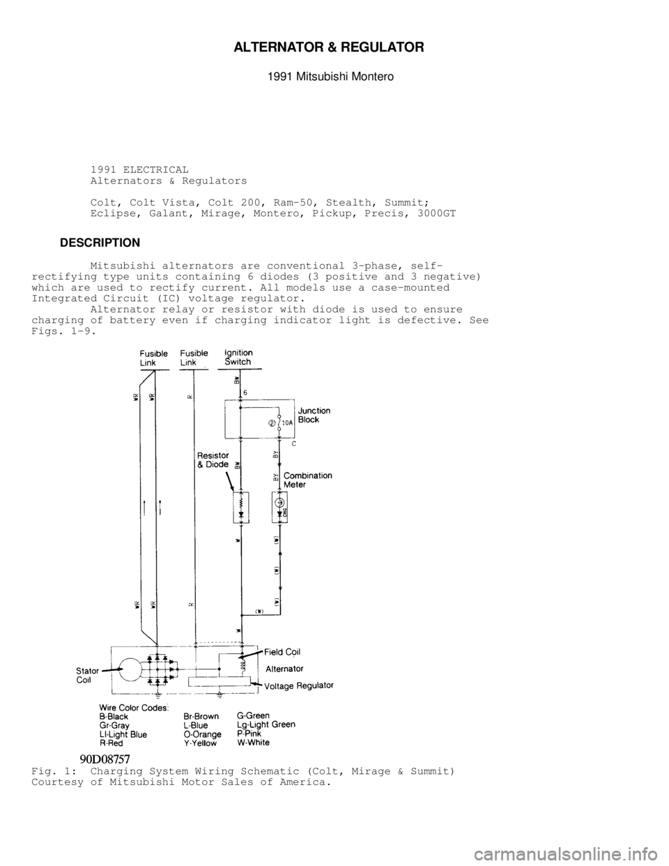
DESCRIPTION
Mitsubishi alternators are conventional 3-phase, self-
rectifying type units containing 6 diodes (3 positive and 3 negative)
which are used to rectify current. All models use a case-mounted
Integrated Circuit (IC) voltage regulator.
Alternator relay or resistor with diode is used to ensure
charging of battery even if charging indicator light is defective. See
Figs. 1 -9.
Fig. 1: Charging System Wiring Schematic (Colt, Mirage & Summit)
Courtesy of Mitsubishi Motor Sales of America.
Page 148 of 1333
Fig. 2: Charging System Wiring Schematic (Colt Vista)
Courtesy of Chrysler Motors.
Page 149 of 1333
Fig. 3: Charging System Wiring Schematic (Eclipse)
Courtesy of Mitsubishi Motor Sales of America.
Page 150 of 1333
Fig. 4: Charging System Wiring Schematic (Galant)
Courtesy of Mitsubishi Motor Sales of America.
Page 151 of 1333
Fig. 5: Charging System Wiring Schematic (Montero)
Courtesy of Mitsubishi Motor Sales of America.
Page 152 of 1333
Fig. 6: Charging System Wiring Schematic (Pickup & Ram-50)
Courtesy of Mitsubishi Motor Sales of America.
Page 153 of 1333
Fig. 7: Charging System Wiring Schematic (Precis)
Courtesy of Mitsubishi Motor Sales of America.

Courtesy of Chrysler Motors.")

Courtesy of Mitsubishi Motor Sales of America.")

Courtesy of Mitsubishi Motor Sales of America.")

Courtesy of Mitsubishi Motor Sales of America.")

Courtesy of Mitsubishi Motor Sales of America.")

Courtesy of Mitsubishi Motor Sales of America.")