Page 1312 of 1333

Model & Ground Apply Voltage
Application Terminal No. To Terminal No.
Low Speed Operation
Montero ...................... 3 ............................. 1
Pickup & Ram-50 .............. 1 ............................. 3
High Speed Operation
Montero ...................... 4 ............................. 1
Pickup & Ram-50 .............. 2 ............................. 3
������������������\
������������������\
������������������\
������������������\
������������������\
������������������\
������������������\
�������������
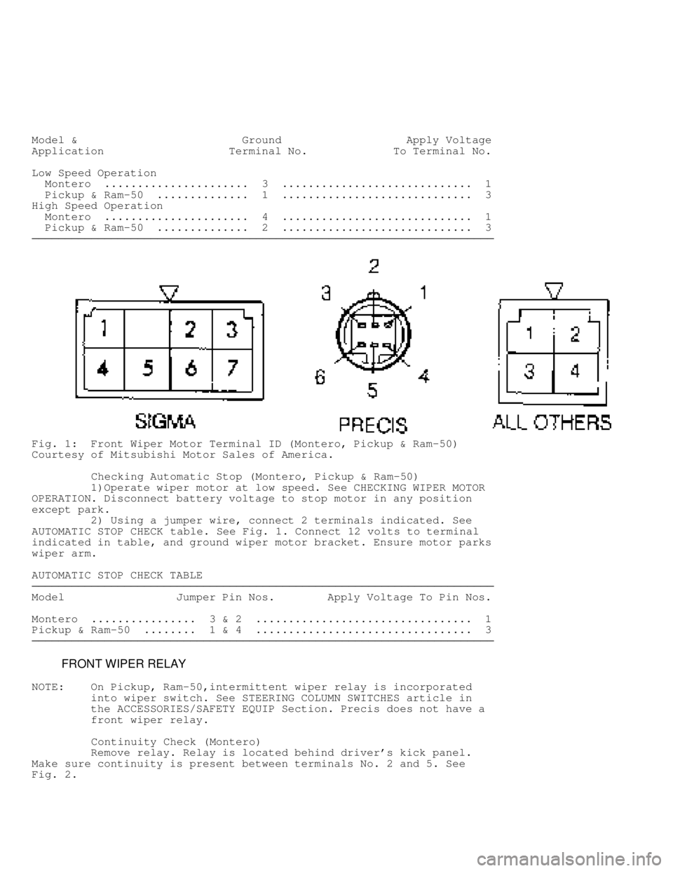
Fig. 1: Front Wiper Motor Terminal ID (Montero, Pickup & Ram-50)
Courtesy of Mitsubishi Motor Sales of America.
Checking Automatic Stop (Montero, Pickup & Ram-50)
1)Operate wiper motor at low speed. See CHECKING WIPER MOTOR
OPERATION. Disconnect battery voltage to stop motor in any position
except park.
2) Using a jumper wire, connect 2 terminals indicated. See
AUTOMATIC STOP CHECK table. See Fig. 1. Connect 12 volts to terminal
indicated in table, and ground wiper motor bracket. Ensure motor parks
wiper arm.
AUTOMATIC STOP CHECK TABLE
������������������\
������������������\
������������������\
������������������\
������������������\
������������������\
������������������\
�������������
Model Jumper Pin Nos. Apply Voltage To Pin Nos.
Montero ................ 3 & 2 ................................. 1
Pickup & Ram-50 ........ 1 & 4 ................................. 3
������������������\
������������������\
������������������\
������������������\
������������������\
������������������\
������������������\
�������������
FRONT WIPER RELAY
NOTE: On Pickup, Ram-50,intermittent wiper relay is incorporated
into wiper switch. See STEERING COLUMN SWITCHES article in
the ACCESSORIES/SAFETY EQUIP Section. Precis does not have a
front wiper relay.
Continuity Check (Montero)
Remove relay. Relay is located behind driver's kick panel.
Make sure continuity is present between terminals No. 2 and 5. See
Fig. 2 .
Page 1313 of 1333

Fig. 2: Identifying Front Wiper Relay Terminals (Montero)
Courtesy of Mitsubishi Motor Sales of America.
Intermittent Operation Check (Montero)
1) Connect battery voltage to terminal No. 1 and ground
terminal No. 6. See Fig. 2. Connect a jumper wire with test light
between battery positive and terminal No. 2.
2) Connect one end of a jumper wire to terminal No. 3 and
touch the other end to negative terminal on battery. Test light should
illuminate briefly and then go out after terminal No. 3 is touched to
battery ground.
FRONT WIPER SWITCH
NOTE: Front wiper switch is located on steering column.
See STEERING COLUMN SWITCHES article in the
ACCESSORIES/SAFETY EQUIP Section.
REAR WIPER MOTOR
Operation Check (Montero)
Disconnect wiring connector from wiper motor. Connect battery
voltage to one terminal and ground to other terminal to ensure
automatic operation. See REAR WIPER MOTOR OPERATION CHECK table for
terminal numbers and model application. See Fig. 3.
REAR WIPER MOTOR OPERATION CHECK TABLE
������������������\
������������������\
������������������\
������������������\
������������������\
������������������\
������������������\
�������������
Model Ground Pin No. Apply Voltage To Pin Nos.
Montero ................. 3 .................................... 1
������������������\
������������������\
������������������\
������������������\
������������������\
������������������\
������������������\
�������������
Page 1315 of 1333
Montero
Remove wiper switch from instrument panel and disconnect
wiring connector. Place wiper switch in OFF position. Continuity
should exist between terminals No. 2 and 5. See Fig. 5. Place wiper
switch in ON position. Continuity should exist between terminals No. 2
and 7. Place wiper switch in INT position. Continuity should exist
between terminals No. 2 and 5, and 3 and 8. Depress washer switch.
Continuity should exist between terminals No. 6 and 7.
Fig. 5: Identifying Rear Wiper Switch Terminals
Courtesy of Mitsubishi Motor Sales of America.
REMOVAL & INSTALLATION
FRONT WIPER MOTOR
Removal & Installation
Remove wiper motor attaching bolts. Pull motor out just
slightly. Disconnect wiper linkage from motor assembly and remove
motor. To install, reverse removal procedure.
FRONT WIPER SWITCH
NOTE: Front wiper switch is integral with combination switch on
steering column. See appropriate STEERING COLUMN SWITCHES