1991 MITSUBISHI ECLIPSE engine coolant
[x] Cancel search: engine coolantPage 523 of 1216
![MITSUBISHI ECLIPSE 1991 Service Manual FUEL SYSTEM - MPI System Inspection <2.0L DOHC Engine>
EGR control solenoid valve
[Calif. only]
Purge control solenoid valve
1
/AF--Y:rIgnition coil, Power transistor
Oxygen sensorPower
steering flu MITSUBISHI ECLIPSE 1991 Service Manual FUEL SYSTEM - MPI System Inspection <2.0L DOHC Engine>
EGR control solenoid valve
[Calif. only]
Purge control solenoid valve
1
/AF--Y:rIgnition coil, Power transistor
Oxygen sensorPower
steering flu](/manual-img/19/57104/w960_57104-522.png)
FUEL SYSTEM - MPI System Inspection <2.0L DOHC Engine>
EGR control solenoid valve
[Calif. only]
Purge control solenoid valve
1
/AF--Y:rIgnition coil, Power transistor
Oxygen sensorPower
steering fluid Dressure switch
Coolant temDerature sensor
Page 526 of 1216

14-72FUEL SYSTEM - MPI Svstem InsDection <2.0L DOHC Engine>
MALFUNCTION INDICATOR LIGHTAmong the self-diagnosis items, a malfunction indicator light
comes on to notify the driver of the emission control items
when an irregularity is detected.
However, when an irregular signal returns to normal and the
engine control unit judges that it has returned to normal. the
malfunction indicator light goes out.
Moreover, when the ignition switch is turned off, the light goes
out. Even if the ignition switch is turned on again, the light doesnot come on until the irregularity is detected.
Here, immediately after the ignition switch is turn on, the
malfunction indicator light is lit for 5 seconds to indicate that
the malfunction indicator light operates normally.
I--l
klfunctionindicator light
Items indicated by the lightening malfunction light
Engine control unit
Oxygen sensor
Air flow sensor
Intake air temperature sensor
Throttle positron sensor
Engrne coolant temperature sensor
Crank angle sensor
Top dead center sensor
Barometric pressure sensor
Detonatron sensor
Injector
Fuel pump
EGR
Ignition co11
/
iMALFUNCTION INDICATOR LIGHT INSPECTION
When turning on the ignition switch, check that the light comes
on.
NOTEIf the light does not come on, check the harness and light for
breakage.
Page 528 of 1216

FUEL SYSTEM- MPI Svstem InsDection <2.0L DOHC Engine>
MPI
diagnosis
I Ground
INSPECTION PROCEDURE - USING VOLTMETERN14PCAGZ
(1) Connect an analogue voltmeter to the self-diagnosis con-
nector.(2) Turn ignition switch to ON, and indication of engine control
unit memory contents will immediately start. If the system
is in normal condition, pointer of voltmeter indicates normalpattern. If any abnormality is in memory, the pointer of
voltmeter will deflect, indicating abnormal item as de-
scribed in “Diagnosis Chart”.
After recording the abnormal item, check and repair each
part according to the check items in “Diagnosis Chart”.
(3) If the defective parts have been repaired, disconnect the
negative terminal of battery cable for
10 seconds or more
and connect it again to make sure that the abnormal code
has been erased.
DIAGNOSIS CHART (FAULT TREE)NlQPRADoutputDiagnosis codeIreference
Dragnosrs Item- Check item (Remedy)
orderOutput signal patternNo.Memory
1Engine controlunit- - W$$ace engine control: I
12A0104
2Oxygen sensor11Retainedl Harness and connector:-J-l-J-0 Oxygen sensor
o Fuel pressure
0 Injectors(Replace if defective)
12A0104l Intake air leaks
3Air flow sensor
:-rLJL ‘*
Retainedl Harness and connector
(If harness and connector
are normal, replace airflow sensor assembly.)
12A0104
4Intake au
J--lNlL l3
Retarnedl Harness and connectortemperature sensor Hl Intake air temperature
sensor
12A0104
5Throttle postron
:n l4
Retainedl Harness and connector
sensorl Throttle position sensorl Idle position switch
17A0104
6Engine coolant
:nn 2’
Retainedl Harness and connectortemperature sensorl Engine coolant temper-
ature sensor
12A0107
Page 530 of 1216

14-76FUEL SYSTEM - MPI Svstem InsDection <2.0L DOHC Enaine>
Air flow sensorsrde connector
6FUO622
6FUO623
16Rl251
INTAKE AIR TEMPERATURE SENSOR
INSPECTION
Nl4OHAB
(1) Disconnect the air flow sensor connectors.
(2) Measure resistance between terminals
@ and @I
(3) Measure resistance between terminals @and @I
Temperature “C (“F)Resistance kR
0 (32)6.0
20
(68)2.7
80 (176)
0.4(4) Measure resistance while heating the sensor using a hair
drier.
Temperature “C (“F)
Higher
Resistance k0
Smaller(5) If the value deviates from the standard value or the
resistance remains unchanged, replace the air flow sensor
assembly.
ENGINE COOLANT TEMPERATURE SENSOR
NlMABEl
INSPECTION
(1) Remove engine coolant temperature sensor from the
intake manifold.
(2) With temperature sensing portion of engine coolant
temperature sensor immersed in hot water, check resist-
ance.
Temperature
“C (“F)
0 (32)
Resistance kfl
5.9
20 (68)2.5
40 (I 04)2.7
80
(I 76)0.3
(3) If the resistance deviates from the standard value greatly,
replace the sensor.
Page 532 of 1216

FUEL SYSTEM - MPI System Inspection <2.0L DOHC Engine>
6FUO999
Accelerator pedal
DepressedContinuity .
Non-conductive
(03 fl)
ReleasedIConductive (0 fl)I(4) Replace the idle position switch if faulty.
NOTE
For replacement procedure, refer to the idle position switch(fixed speed adjusting screw) adjustment section
(P.14-
52.).OXYGEN SENSOR
NllQDeJ
INSPECTION(1) Disconnect the oxygen sensor connector.
(2) Check that there is continuity [approx. 12
52 at 20°C (68”F)l
between oxygen sensor connector terminal @ and terminal
GO.(3) If there is no continuity, replace the oxygen sensor.
(4) Warm up the engine until the engine coolant temperature
exceeds
80°C (176°F).(5) Use jumper wires to connect oxygen sensor terminal
@and terminal
@ to the battery @ terminal and 0 terminal.
Caution
Be very careful when connecting the jumper wires
because the oxygen sensor will be damaged if a
mistake is made in the connecting terminals.
(6) Connect a digital voltmeter between terminal
@ and
terminal
0.(7) While repeatedly racing the engine, measure the ‘output
voltage of the oxygen sensor.
When racing
engineWhen the
air/fuel mixture raticINSTALLATION
1. For removal and installation of oxygen sensor, refer to
GROUP 11
- Exhaust Manifold.
2. Oxygen sensor tighten to specified torque.
Specified torque: 40
- 50 Nm (29 - 36 ft.lbs.)
Page 896 of 1216

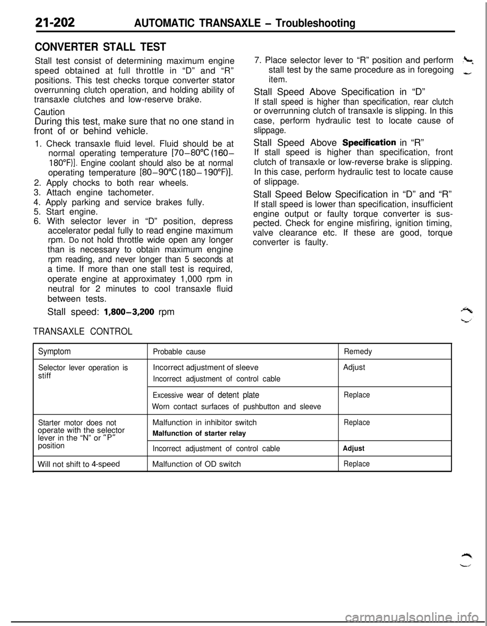
21-202AUTOMATIC TRANSAXLE - Troubleshooting
CONVERTER STALL TESTStall test consist of determining maximum engine
speed obtained at full throttle in “D” and “R”
positions. This test checks torque converter stator
overrunning clutch operation, and holding ability of
transaxle clutches and low-reserve brake.
CautionDuring this test, make sure that no one stand in
front of or behind vehicle.
1. Check transaxle fluid level. Fluid should be at
normal operating temperature
[70-80°C (160-
18O”F)]. Engine coolant should also be at normaloperating temperature
[80-90°C (180- 19O”F)l.2. Apply chocks to both rear wheels.
3. Attach engine tachometer.
4. Apply parking and service brakes fully.
5. Start engine.
6. With selector lever in “D” position, depress
accelerator pedal fully to read engine maximum
rpm. Do not hold throttle wide open any longer
than is necessary to obtain maximum engine
rpm reading, and never longer than 5 seconds ata time. If more than one stall test is required,
operate engine at approximatey 1,000 rpm in
neutral for 2 minutes to cool transaxle fluid
between tests.
Stall speed:
1,800-3,200 rpm
TRANSAXLE CONTROL7. Place selector lever to “R” position and perform
?+stall test by the same procedure as in foregoing
-,
item.Stall Speed Above Specification in “D”
If stall speed is higher than specification, rear clutchor overrunning clutch of transaxle is slipping. In this
case, perform hydraulic test to locate cause of
slippage.Stall Speed Above Specifjcation in “R”
If stall speed is higher than specification, front
clutch of transaxle or low-reverse brake is slipping.
In this case, perform hydraulic test to locate cause
of slippage.
Stall Speed Below Specification in “D” and “R”
If stall speed is lower than specification, insufficient
engine output or faulty torque converter is sus-
pected. Check for engine misfiring, ignition timing,
valve clearance etc. If these are good, torque
converter is faulty.
Symptom
Selector lever operation isstiff
Probable causeIncorrect adjustment of sleeve
Incorrect adjustment of control cable
Excessive wear of detent plate
Worn contact surfaces of pushbutton and sleeveRemedyAdjust
Replace
Starter motor does notoperate with the selector
lever in the “N” or
“P”position
Will not shift to
4-speedMalfunction in inhibitor switch
Malfunction of starter relay
Incorrect adjustment of control cableMalfunction of OD switch
Replace
Adjust
Replace
Page 1145 of 1216

24-l
HEATERS ANDAIR CONDITIONING
CONTENTSN24M--AIR CONDITIONER SWITCH
..........................30BLOWER ASSEMBLY
.....................................33
COMPRESSOR.................................................37CONDENSER AND CONDENSER FAN
MOTOR............................................................45ENGINE COOLANT TEMPERATURE
-‘-.,SWITCH............................................................51
EVAPORATOR.................................................
34
HEATERCONTROLASSEMBLY....................
26HEATER UNIT
.................................................31
REFRIGERANTLINE........................................47
RESISTOR........................................................29SAFETY PRECAUTIONS
.................................10SERVICE ADJUSTMENT PROCEDURES..
.....11Compressor Drive
Belt Adjustment
.............
23
CompressorNoise........................................24
Handling
TubingandFittings.......................22Idle-up
OperationCheck..............................25Manifold
GaugeSetInstallation..................11Performance Test
.........................................16Power Relay Check
......................................24Refrigerant Leak Repair Procedure
.............17
TestingSystemforLeaks...........................15Test Procedures
...........................................11
SPECIFICATIONS.............................................2
General Specifications..................................2
Lubricants......................................................3Sealant and Adhesives
.................................3Service Specifications
...................................2
TorqueSpecifications...................................2
TROUBLESHOOTING. . . ..a................................3
VENTILATORS(AIR INLET AND AIR OUTLET)
..,....s............. 50
VENTILATORS(INSTRUMENT PANEL)
..,...................*...........49
Page 1146 of 1216

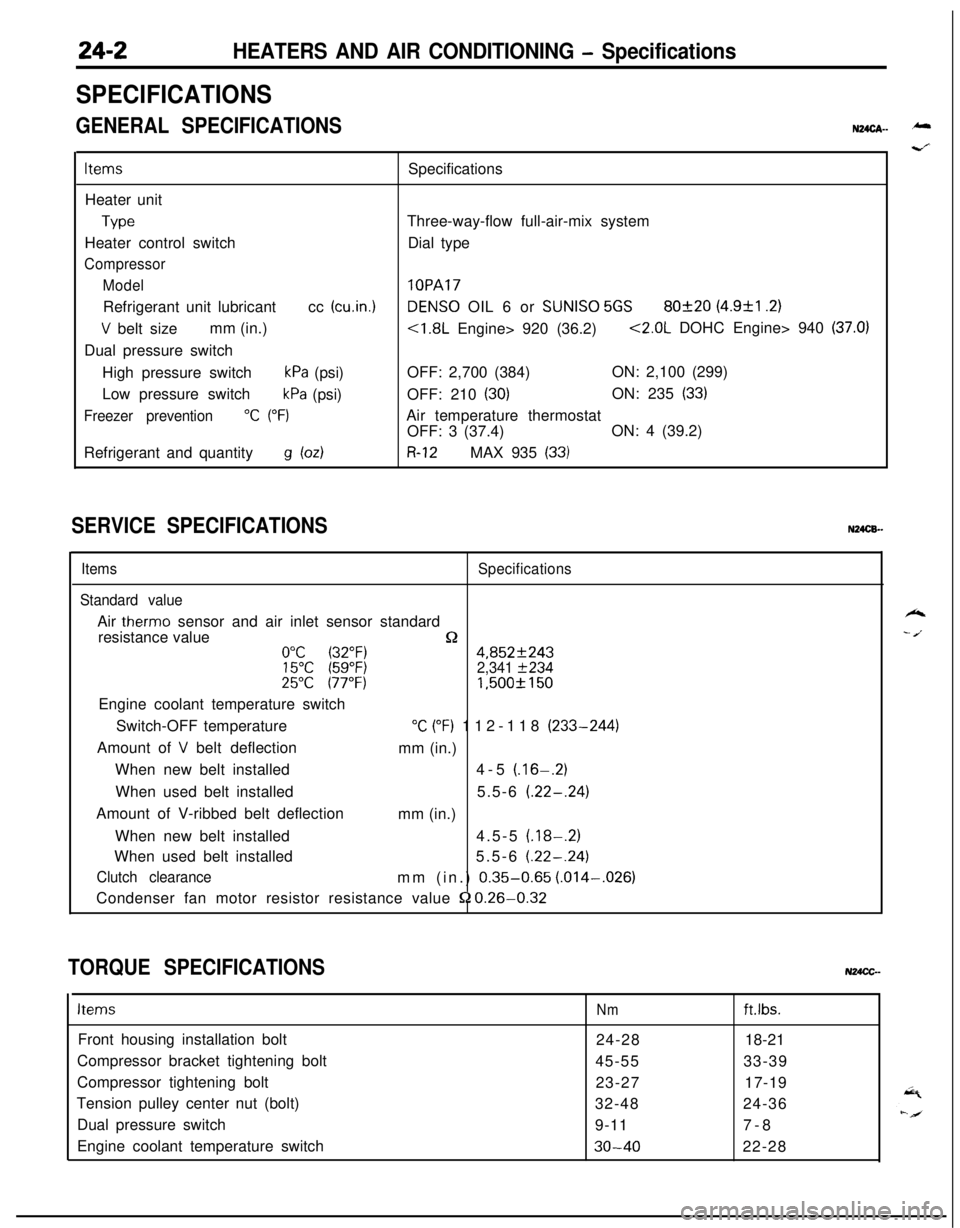
24-2HEATERS AND AIR CONDITIONING - Specifications
SPECIFICATIONS
GENERAL SPECIFICATIONSN24cA- -
ItemsSpecifications
Heater unit
TypeThree-way-flow full-air-mix system
Heater control switchDial type
Compressor
Model
lOPARefrigerant unit lubricantcc
(cu.in.1DENS0 OIL 6 or SUNISO 5GS80f20 (4.9&l .2)
V belt sizemm (in.)<1.8L Engine> 920 (36.2)<2.0L DOHC Engine> 940 (37.0)Dual pressure switch
High pressure switch
kPa (psi)OFF: 2,700 (384)ON: 2,100 (299)
Low pressure switch
kPa (psi)OFF: 210 (30)ON: 235 (33)
Freezer prevention“C (“F)Air temperature thermostat
OFF: 3 (37.4)ON: 4 (39.2)
Refrigerant and quantity
g bdR-12MAX 935 (33)
SERVICE SPECIFICATIONSN24CB.-
ItemsSpecifications
Standard valueAir
therm0 sensor and air inlet sensor standard
resistance value
n0°C (32°F)4,852f24315°C (59°F)2,341 f23425°C 177°F)1,500f 150Engine coolant temperature switch
Switch-OFF temperature
“C (“F) 112-118 (233-244)
Amount of
V belt deflection
mm (in.)
When new belt installed4-5
(.16-.2)When used belt installed5.5-6
(.22-.24)Amount of V-ribbed belt deflection
mm (in.)
When new belt installed4.5-5
(.18-.2)When used belt installed5.5-6
(.22-.24)
Clutch clearancemm (in.) 0.35-0.65 (.014-,026)
Condenser fan motor resistor resistance value
52 0.26-0.32
TORQUE SPECIFICATIONSN24CC-
ItemsNmft.lbs.Front housing installation bolt
24-2818-21
Compressor bracket tightening bolt
45-5533-39
Compressor tightening bolt
23-2717-19
Tension pulley center nut (bolt)
32-4824-36
Dual pressure switch
9-117-8
Engine coolant temperature switch
30-4022-28
k
- /.