1991 MITSUBISHI ECLIPSE check engine
[x] Cancel search: check enginePage 327 of 1216
ENGINE <1.8L Engine> - Timing Belt9-43
-
.
4iJ
:
,000008
7EN206
Crack
7EN207Abnormal wear
(fluffy canvas fiber)7EN2013
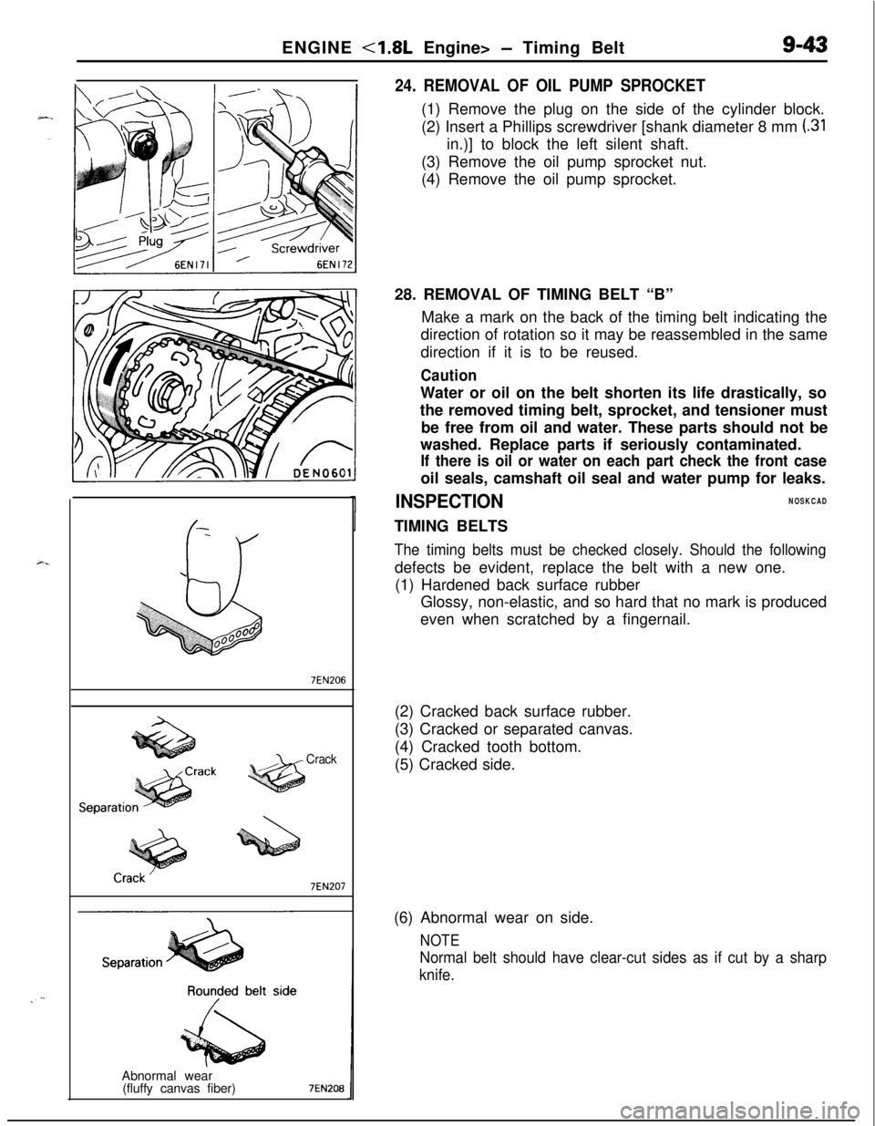
24. REMOVAL OF OIL PUMP SPROCKET(1) Remove the plug on the side of the cylinder block.
(2) Insert a Phillips screwdriver [shank diameter 8 mm
(.31in.)] to block the left silent shaft.
(3) Remove the oil pump sprocket nut.
(4) Remove the oil pump sprocket.
28. REMOVAL OF TIMING BELT “B”
Make a mark on the back of the timing belt indicating the
direction of rotation so it may be reassembled in the same
direction if it is to be reused.
CautionWater or oil on the belt shorten its life drastically, so
the removed timing belt, sprocket, and tensioner must
be free from oil and water. These parts should not be
washed. Replace parts if seriously contaminated.
If there is oil or water on each part check the front caseoil seals, camshaft oil seal and water pump for leaks.
INSPECTIONNOSKCADTIMING BELTS
The timing belts must be checked closely. Should the followingdefects be evident, replace the belt with a new one.
(1) Hardened back surface rubber
Glossy, non-elastic, and so hard that no mark is produced
even when scratched by a fingernail.
(2) Cracked back surface rubber.
(3) Cracked or separated canvas.
(4) Cracked tooth bottom.
(5) Cracked side.
(6) Abnormal wear on side.
NOTE
Normal belt should have clear-cut sides as if cut by a sharp
knife.
Page 328 of 1216
9-44ENGINE <1.8L Engine> - Timing Belt
Rubber
exposedTooth missing and
1 EN0002
Crankshaftsprocket “6
Crankshaft 6EN304
Spacer
Chamfered
6EN009
J
TiGGrnmarkCrankshaft
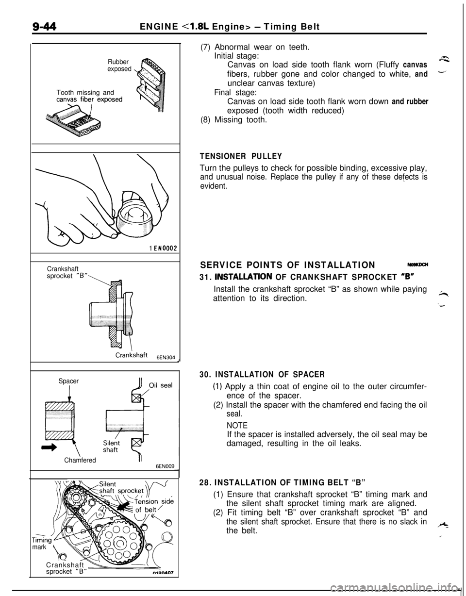
\vsprocket “B”(7) Abnormal wear on teeth.
Initial stage:
Canvas on load side tooth flank worn (Fluffy canvas
afibers, rubber gone and color changed to white, and
-unclear canvas texture)
Final stage:Canvas on load side tooth flank worn down and rubber
exposed (tooth width reduced)
(8) Missing tooth.
TENSIONER PULLEYTurn the pulleys to check for possible binding, excessive play,
and unusual noise. Replace the pulley if any of these defects is
evident.”
SERVICE POINTS OF INSTALLATION
31. INSTALLATlON OF CRANKSHAFT SPROCKET “6”Install the crankshaft sprocket “B” as shown while paying
attention to its direction.
~,
‘d
30. INSTALLATION OF SPACER
(1) Apply a thin coat of engine oil to the outer circumfer-
ence of the spacer.
(2) Install the spacer with the chamfered end facing the oil
seal.
NOTEIf the spacer is installed adversely, the oil seal may be
damaged, resulting in the oil leaks.
28. INSTALLATION OF TIMING BELT “B”(1) Ensure that crankshaft sprocket “B” timing mark and
the silent shaft sprocket timing mark are aligned.
(2) Fit timing belt “B” over crankshaft sprocket “B” and
the silent shaft sprocket. Ensure that there is no slack inthe belt.+
a.
Page 330 of 1216
9-46ENGINE <1.8L Engine> - Timing Belt
Timing mark
Q1hQS4.9
3EN005
OlA0549
c
::
OlAO550-(3) Move tensioner fully toward water pump and tempor-
arily secure tensioner.
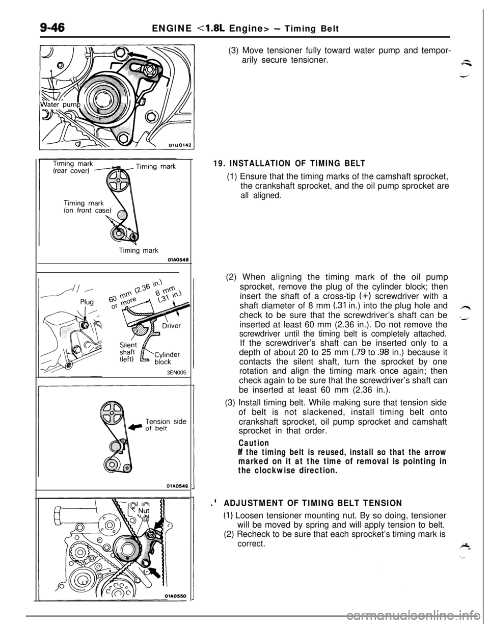
19. INSTALLATION OF TIMING BELT(1) Ensure that the timing marks of the camshaft sprocket,
the crankshaft sprocket, and the oil pump sprocket are
all aligned.(2) When aligning the timing mark of the oil pump
sprocket, remove the plug of the cylinder block; then
insert the shaft of a cross-tip (+) screwdriver with a
shaft diameter of 8 mm
(.31 in.) into the plug hole and
check to be sure that the screwdriver’s shaft can be
inserted at least 60 mm (2.36 in.). Do not remove the
screwdriver until the timing belt is completely attached.If the screwdriver’s shaft can be inserted only to a
depth of about 20 to 25 mm
(.79 to .98 in.) because it
contacts the silent shaft, turn the sprocket by one
rotation and align the timing mark once again; then
check again to be sure that the screwdriver’s shaft can
be inserted at least 60 mm (2.36 in.).
(3) Install timing belt. While making sure that tension side
of belt is not slackened, install timing belt onto
crankshaft sprocket, oil pump sprocket and camshaft
sprocket in that order.
Caution
If the timing belt is reused, install so that the arrow
marked on it at the time of removal is pointing in
the clockwise direction..
ADJUSTMENT OF TIMING BELT TENSION
(1) Loosen tensioner mounting nut. By so doing, tensioner
will be moved by spring and will apply tension to belt.
(2) Recheck to be sure that each sprocket’s timing mark is
correct.
Page 331 of 1216
ENGINE <1.8L Engine> - Timing Belt9-47
Timing mark
Nut
;olt diameter x lengthim (in.)
6x50(.23 x 1.97)
6
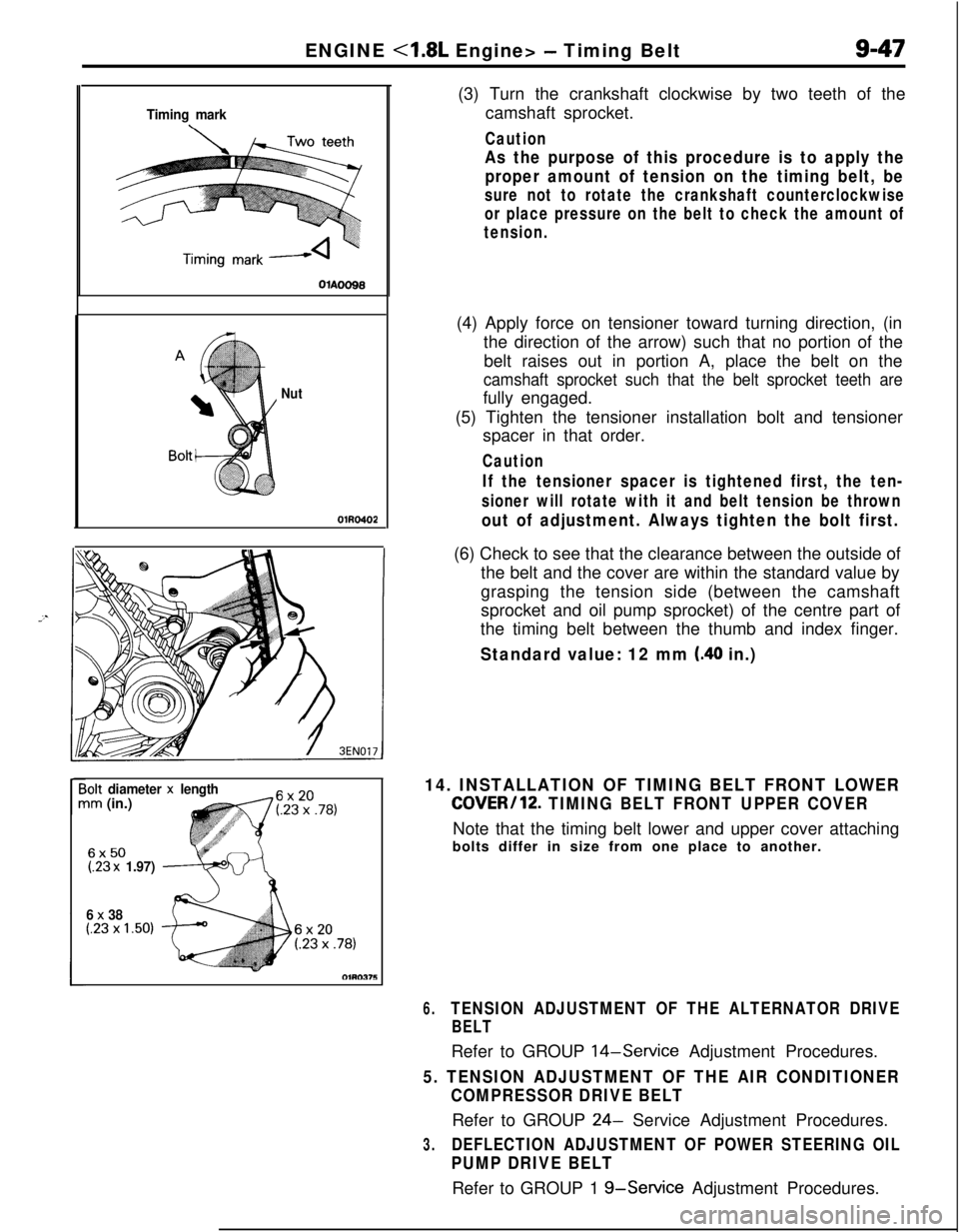
x 38(.23 x 1.50)(3) Turn the crankshaft clockwise by two teeth of the
camshaft sprocket.
Caution
As the purpose of this procedure is to apply the
proper amount of tension on the timing belt, be
sure not to rotate the crankshaft counterclockwise
or place pressure on the belt to check the amount of
tension.(4) Apply force on tensioner toward turning direction, (in
the direction of the arrow) such that no portion of the
belt raises out in portion A, place the belt on the
camshaft sprocket such that the belt sprocket teeth arefully engaged.
(5) Tighten the tensioner installation bolt and tensioner
spacer in that order.
Caution
If the tensioner spacer is tightened first, the ten-
sioner will rotate with it and belt tension be thrown
out of adjustment. Always tighten the bolt first.(6) Check to see that the clearance between the outside of
the belt and the cover are within the standard value by
grasping the tension side (between the camshaft
sprocket and oil pump sprocket) of the centre part of
the timing belt between the thumb and index finger.
Standard value: 12 mm (.40 in.)
14. INSTALLATION OF TIMING BELT FRONT LOWER
COVER/12. TIMING BELT FRONT UPPER COVERNote that the timing belt lower and upper cover attaching
bolts differ in size from one place to another.
6.TENSION ADJUSTMENT OF THE ALTERNATOR DRIVE
BELTRefer to GROUP
14-Service Adjustment Procedures.
5. TENSION ADJUSTMENT OF THE AIR CONDITIONER
COMPRESSOR DRIVE BELTRefer to GROUP
24- Service Adjustment Procedures.
3.DEFLECTION ADJUSTMENT OF POWER STEERING OIL
PUMP DRIVE BELTRefer to GROUP 1
g-Service Adjustment Procedures.
Page 333 of 1216
ENGINE <1.8L Ennine> -Rocker Arms, Rocker Arm Shafts and Camshaft&49
MD9984431
6EN245
IFuel pump
3EN287
r
0
Camheight6EN0184
hl,
3EN153, Oil seal
MD998364
DEN632
SERVICE POINTS OF DISASSEMBLYNWLFM.
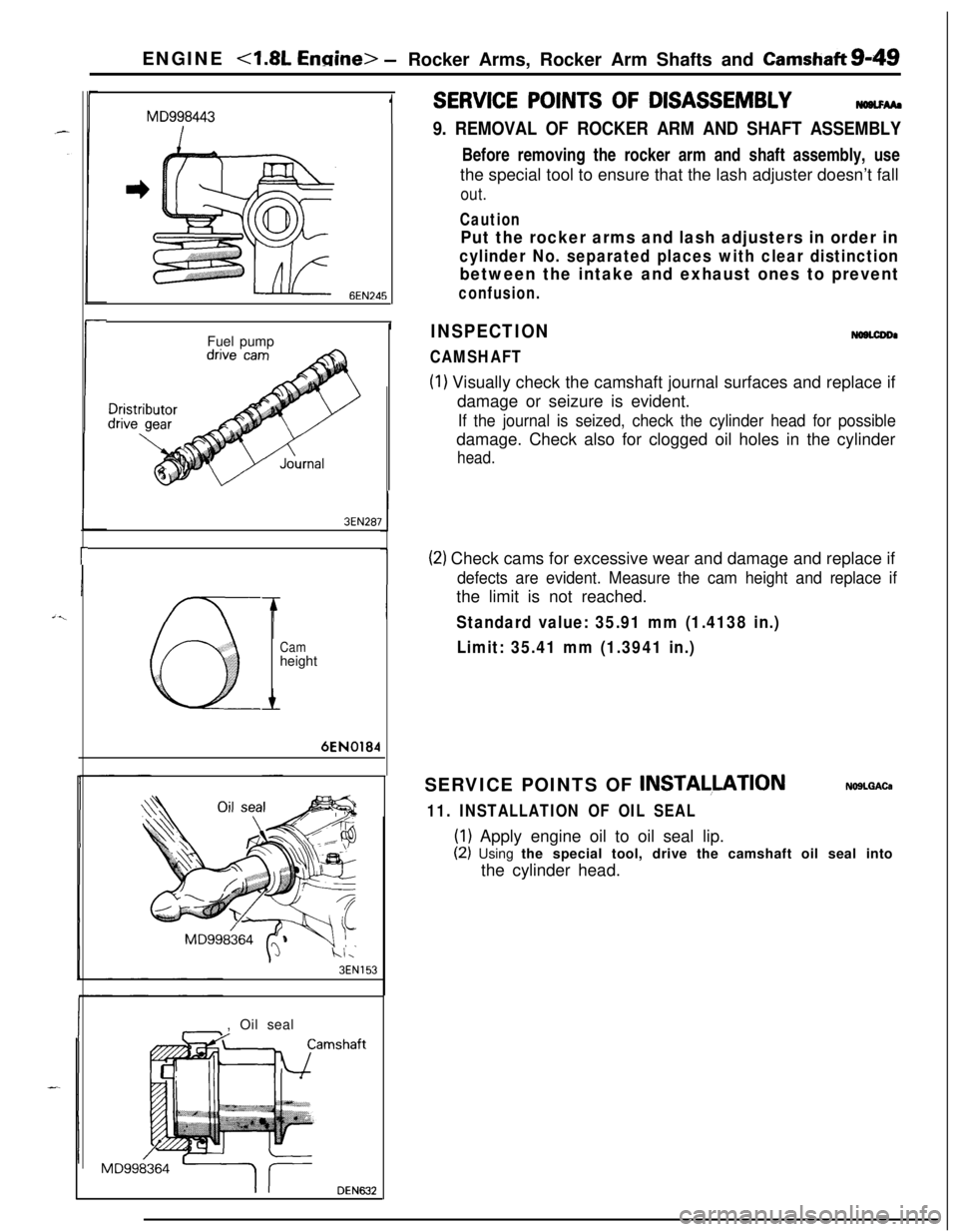
9. REMOVAL OF ROCKER ARM AND SHAFT ASSEMBLYBefore removing the rocker arm and shaft assembly, use
the special tool to ensure that the lash adjuster doesn’t fall
out.
Caution
Put the rocker arms and lash adjusters in order in
cylinder No. separated places with clear distinction
between the intake and exhaust ones to prevent
confusion.
INSPECTION
CAMSHAFT
NOBLCDDI
(1) Visually check the camshaft journal surfaces and replace if
damage or seizure is evident.
If the journal is seized, check the cylinder head for possibledamage. Check also for clogged oil holes in the cylinder
head.
(2) Check cams for excessive wear and damage and replace if
defects are evident. Measure the cam height and replace ifthe limit is not reached.
Standard value: 35.91 mm (1.4138 in.)
Limit: 35.41 mm (1.3941 in.)SERVICE POINTS OF
INSTALLATIONNOSLQACa
11. INSTALLATION OF OIL SEAL
(1) Apply engine oil to oil seal lip.
(2) Using the special tool, drive the camshaft oil seal into
the cylinder head.
Page 336 of 1216
7EN0064
IIENGINE
<1.8L Engine> -Rocker Arms and Rocker Shafts
SERVICE POINTS OF DISASSEMBLY
NOTEBefore disassembly, mark the rocker arm for
indentificahon.
INSPECTIONNoaNGAG
ROCKER ARM(1) Visually check the roller and replace if dent, damage, or
seizure is evident.
(2) Check roller for smooth rotation. Replace if it is binds or
there is an excessive play.
ICuts in rocker shafts(3) Check the inside diameter and replace the rocker arm if
damage or seizure is observed.SERVICE POINTS OF REASSEMBLYNOBNHBC
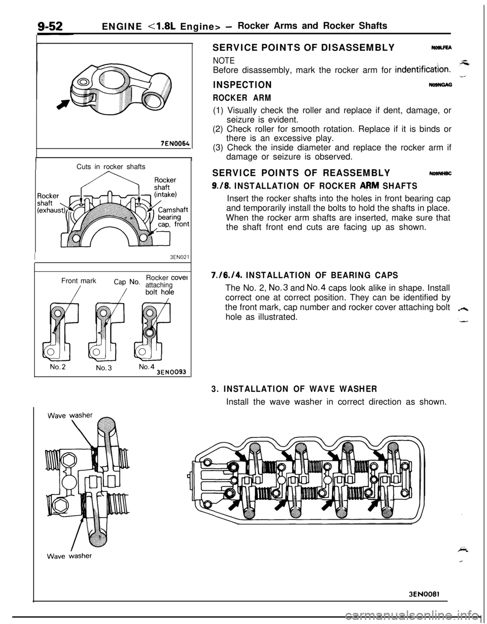
9./8. INSTALLATION OF ROCKER AeM SHAFTSInsert the rocker shafts into the holes in front bearing cap
and temporarily install the bolts to hold the shafts in place.
When the rocker arm shafts are inserted, make sure that
the shaft front end cuts are facing up as shown.
I3EN021Front mark
Cap No.Rocker cove1attaching
No.2No.3No.43EN0093
7./6./4. INSTALLATION OF BEARING CAPSThe No. 2, No.3 and No.4 caps look alike in shape. Install
correct one at correct position. They can be identified by
the front mark, cap number and rocker cover attaching bolt
hole as illustrated.
3. INSTALLATION OF WAVE WASHERInstall the wave washer in correct direction as shown.
3EN0081
Page 339 of 1216
ENGINE - Cylinder Head and Valve9-55
3EN026
w -w===j=Margin , EN034
Squareness
IFree length
INSPECTION
CYLINDER HEADNosocAMl Check the cylinder head for cracks, damage and engine
coolant leakage.l
Remove the scale, sealing compound and carbon deposits
completely. After cleaning oil passages, apply compressedair to make certain that the passages are clear.
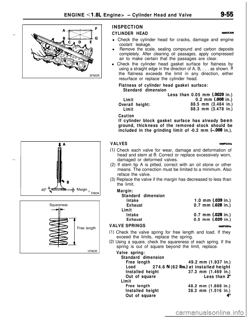
l Check the cylinder head gasket surface for flatness by
using a straight edge in the direction of A, B, . . . as shown. Ifthe flatness exceeds the limit in any direction, either
resurface or replace the cylinder head.
Flatness of cylinder head gasket surface:
Standard dimension
Limit
Overall height:
Limit
Caution
Less than 0.05 mm (0020 in.)
0.2 mm (008 in.)
88.5 mm (3.484 in.)
88.3 mm (3.478 in.)
If cylinder block gasket surface has already been
ground, thickness of the removed stock should be
included in the grinding limit of -0.2 mm
(-,008 in.).
VALVESNo9PGMa
(1) Check each valve for wear, damage and deformation of
head and stem at
B. Correct or replace excessively worn,
damaged or deformed valves.
(2) If stem tip A is pitted, correct with an oil stone or other
means. The correction must be limited to a minimum. Also
reface the valve.
(3) Replace the valve if the margin has decreased to less than
the limit.
Margin:
Standard dimension
Intake1.0 mm (.039 in.)
Exhaust0.7 mm (028 in.)
Limit
Intake0.7 mm (.028 in.)
Exhaust0.5 mm LO20 in.)
VALVE SPRINGSNOWGh
(1) Check the valve spring for free length and load. If they
exceed the limits, replace the spring.
(2) Using a square, check the squareness of each spring. If thespring is out of square beyond the limit, replace.
Valve spring:
Standard dimension
Free length
49.2 mm (1.937 in.)
Load274.6 N (62 Ibs.) at installed height
Installed height37.3 mm (1.469 in.)
Out of square
Less than 2”
Limit
Free length48.2 mm (1.888 in.)
Installed height38.3 mm (1.516 in.)
Out of square4”
Page 340 of 1216
9-56ENGINE <1.8L Engine> - Cylinder Head and ValveStem O.D.
YEN323
3EN0039
-I
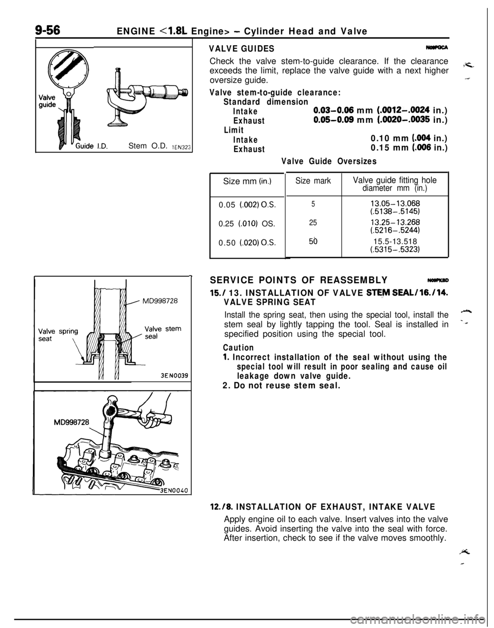
VALVE GUIDESCheck the valve stem-to-guide clearance. If the clearance
exceeds the limit, replace the valve guide with a next higher
7-c.oversize guide.“I
Valve stem-to-guide clearance:
Standard dimension
Intake0.03-0.06 mm (.0012-.0024 in.)
Exhaust0.05-0.08 mm (.0020-.0035 in.)
Limit
Intake0.10 mm (004 in.)
Exhaust0.15 mm (.006 in.)
Valve Guide OversizesSize mm
(in.)0.05
l.002) OS.0.25
LOlO) OS.
0.50
i.020) OS.
Size markValve guide fitting holediameter mm (in.)
513.05-13.068(.5138-.5145)
2513.25-13.268(.5216-.5244)
5015.5-13.518(.5315-.5323)
SERVICE POINTS OF REASSEMBLY
15./ 13. INSTALLATION OF VALVE STE,M SEAL/l6./14.
VALVE SPRING SEAT
Install the spring seat, then using the special tool, install the-stem seal by lightly tapping the tool. Seal is installed in
-dspecified position using the special tool.
Caution
1. Incorrect installation of the seal without using the
special tool will result in poor sealing and cause oil
leakage down valve guide.
2. Do not reuse stem seal.
12.18. INSTALLATION OF EXHAUST, INTAKE VALVEApply engine oil to each valve. Insert valves into the valve
guides. Avoid inserting the valve into the seal with force.
After insertion, check to see if the valve moves smoothly.PL