Page 1190 of 1216
24-46HEATERS AND AIR CONDITIONING - c donenser and Condenser Fan Motor
20A0407-INSPECTION
ntarTual Check the condenser fin for crushing or other damage.,
l Check the condenser’s high-pressure hose and pipe in-
stallation parts for damage or deformation.
l Check the condenser fan shroud for damage.
CONDENSER FAN MOTOR CHECK
(1) Disconnect the connection of the connector for the
condenser fan motor.
(2) Check to be sure that the condenser fan motor operates
when battery voltage is applied to terminal
@I and terminal
@ is grounded.
RESISTOR CHECK(1) Disconnect the connection of the connector for the
resistor, and then measure the resistance between termi-
nals.(2) The condition can be considered satisfactory if the mea-
sured resistance is within the range noted below.
Standard value:
0.26-0.32 52SERVICE POINTS OF
INSTALLATtONN24lVAE8. CONNECTION OF LIQUID PIPE/7. DISCHARGE PIPE
Refer to
P.24-23.
Page 1191 of 1216
HEATERS AND AIR CONDITIONING - Refrigerant Line24-47
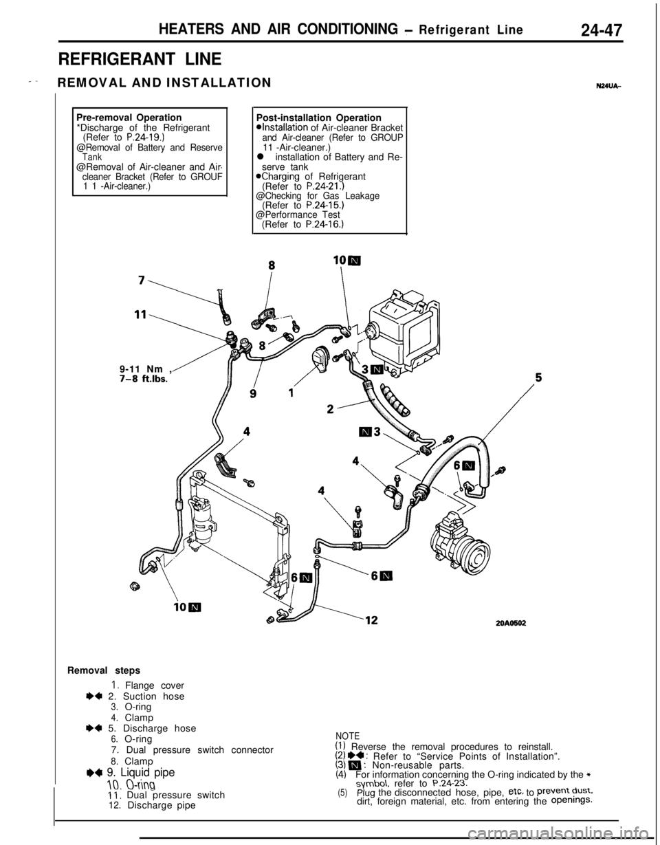
REFRIGERANT LINE
- -REMOVAL AND INSTALLATIONN24UA-Pre-removal Operation
*Discharge of theRefrigerant
(Refer to
P.24-19.)@Removal of Battery and ReserveTank@Removal of Air-cleaner and Aircleaner Bracket (Refer to GROUF
1 1 -Air-cleaner.)Post-installation Operation
@Installation of Air-cleaner Bracketand Air-cleaner (Refer to GROUP11 -Air-cleaner.)
l installation of Battery and Re-
serve tank
Kharging of Refrigerant
(Refer to P.24-21.)@Checking for Gas(Refer to P.24-15.)Leakage
@Performance Test(Refer to
P.24-16.)9-11 Nm ,
7-8 ft.lbs.
20AO502Removal steps
I. Flange cover
I)+ 2. Suction hose3.O-ring
4.ClampI)* 5. Discharge hose6.O-ring
7. Dual pressure switch connector
8.Clamp
e+ 9. Liquid pipe
10.O-ring11, Dual pressure switch12.Dischargepipe
NOTE(1) Reverse the removal procedures to reinstall.(2) I)4 : Refer to “Service Points of Installation”.(3) N : Non-reusable parts.(4)For information concerning the O-ring indicated by the *symbo\. refer to P.24.23.(5)plug the disconnected hose, pipe, etc, to Prevent dust.dirt, foreign material, etc. from entering the Openings.
Page 1192 of 1216
24-48HEATERS AND AIR CONDITIONING - Refrigerant Line
SERVICE POINTS OF INSTALLATION9. INSTALLATION OF LIQUID PIPE
Caution
1. Keep the gap more than 5 mm
(.2 in.) between
liquid pipe and clutch tube.
2. Keep the gap more than 15 mm
(.6 in.) betWeenliquid pipe connected condenser and body.
5. INSTALLATION OF DISCHARGE HOSE
Caution
Keep the gap more than 25 mm (1
in.1 between
accelerator cable and discharge hose.
2. INSTALLATION OF SUCTION HOSE
Caution
Make sure that suction hose does not interfere with
heater hose and mission cable.
Page 1193 of 1216
HEATERS AND AIR CONDITIONING- Ventilators (Instrument Panel)24-49
16
VENTILATORS (INSTRUMENT PANEL)
I- -REMOVAL AND INSTALLATION
,’ !‘\
19< !.an
6. Lap cooler duct (B)
2OAO420
a*7. Center air outlet assembly8. Shower duct
R’H.+* l a9. Instrument panel10. Distribution foot duct
11. Center duct assembly
12. Lao cooler duct IA)13. AiFduct (A)14. Air duct (B)15. Distribution duct16. Side defroster hoses
17. Defroster nozzle assembly
18. Side defroster grilles
19. Side air outlet assemblyRemoval steps
1. Plug2. Knee protecter
3. Hood lock release handle
4. Lap cooler grilleNOTE(1) Reverse the removal procedures to reinstall.
(2) l * : Refer to “Service Points of Removal”.
5. Shower duct L.H.(3) l a : Refer to “Service Points of Installation”.
SERVICE POINTS OF REMOVAL
NZNBAG7. REMOVAL OF CENTER AIR OUTLET ASSEMBLY/
9. INSTRUMENT PANEL
Refer to GROUP
23-Instrument Panel.
SERVICE POINTS OF INSTAUAT-ION9. INSTALLATION OF INSTRUMENT PANEL
Refer to GROUP
23-Instrument Panel.
Page 1194 of 1216
24-50HEATERS AND AIR CONDITIONING -Ventilators (Air Inlet and Air Outlet)
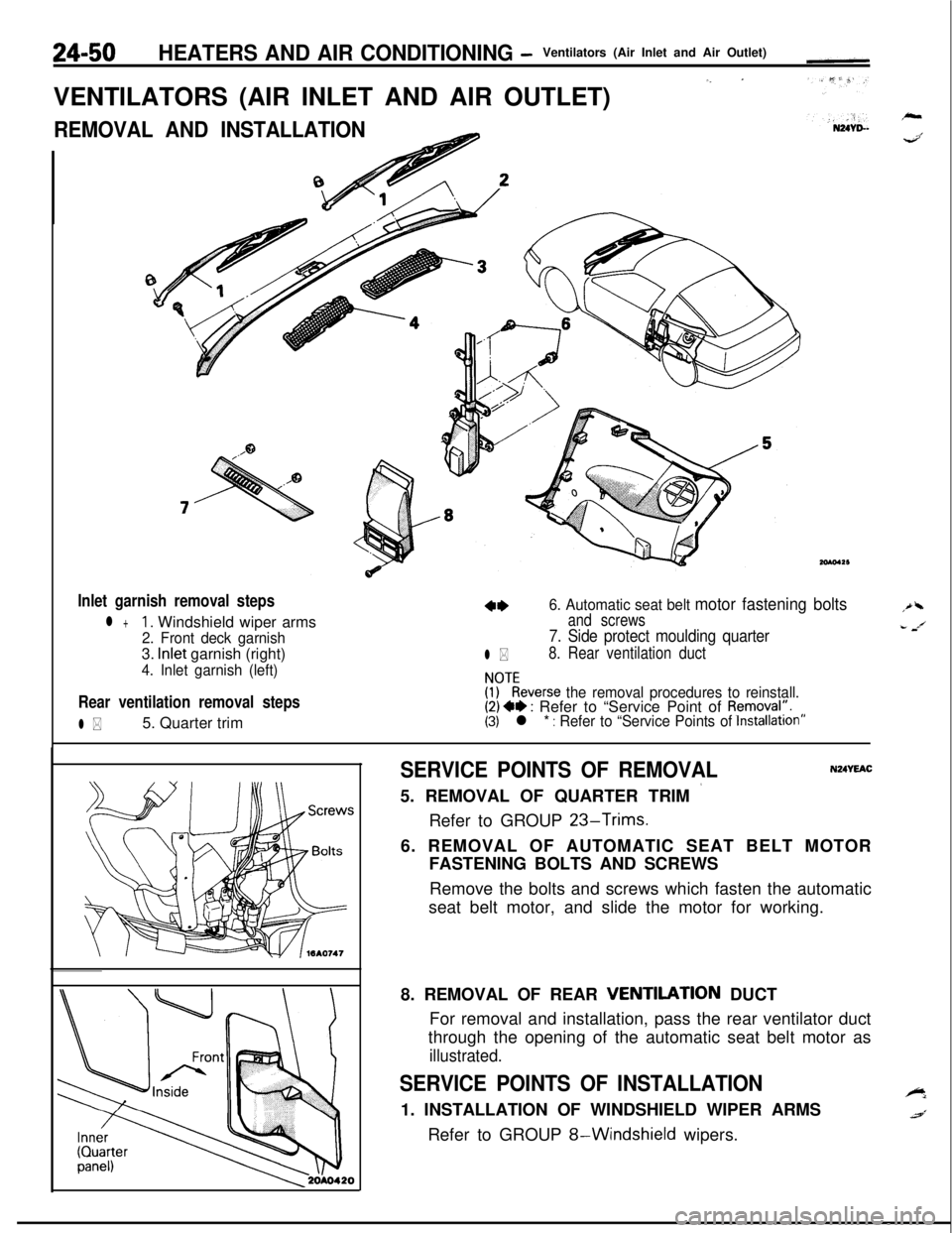
VENTILATORS (AIR INLET AND AIR OUTLET)
‘- ’
REMOVAL AND INSTALLATION
Inlet garnish removal steps
l +1. Windshield wiper arms
2. Front deck garnish3.
Inlet garnish (right)
4. Inlet garnish (left)
Rear ventilation removal steps
l *5. Quarter trim
6. Automatic seat belt motor fastening bolts
and screws
l *
7. Side protect moulding quarter
8. Rear ventilation duct
!PTkeverse the removal procedures to reinstall.(2) +* : Refer to “Service Point of Removal:.(3) l * : Refer to “Service Points of Installation”
SERVICE POINTS OF REMOVAL5. REMOVAL OF QUARTER TRIM
’Refer to GROUP
23-Trims.
N24YEAC6. REMOVAL OF AUTOMATIC SEAT BELT MOTOR
FASTENING BOLTS AND SCREWS
Remove the bolts and screws which fasten the automatic
seat belt motor, and slide the motor for working.
8. REMOVAL OF REAR
VENTllATlON DUCT
For removal and installation, pass the rear ventilator duct
through the opening of the automatic seat belt motor as
illustrated.
SERVICE POINTS OF INSTALLATION1. INSTALLATION OF WINDSHIELD WIPER ARMS
Refer to GROUP
8-Windshield wipers.
Page 1195 of 1216
HEATERS AND AIR CONDITIONING- Engine Coolant Temperature Switch24-51
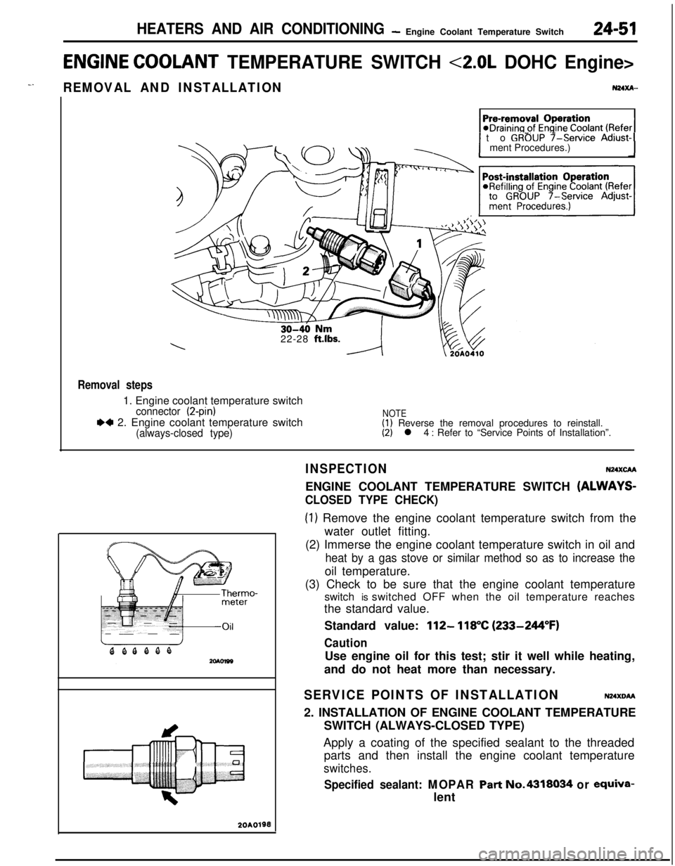
ENGINE COOLANT TEMPERATURE SWITCH <2.0L DOHC Engine>
-.REMOVAL AND INSTALLATIONN24xA-
1 to GROUP f-service Adjust-1ment Procedures.)
22-28
ft.lbs.
Removal steps1. Engine coolant temperature switch
connector (2-pin)
.4 2. Engine coolant temperature switch(always-closed type)
NOTE(1) Reverse the removal procedures to reinstall.(2) l 4 : Refer to “Service Points of Installation”.
20A0190I
INSPECTIONN24XcAAENGINE COOLANT TEMPERATURE SWITCH
(ALWAYS-
CLOSED TYPE CHECK)
(1) Remove the engine coolant temperature switch from the
water outlet fitting.
(2) Immerse the engine coolant temperature switch in oil and
heat by a gas stove or similar method so as to increase theoil temperature.
(3) Check to be sure that the engine coolant temperature
switch is switched OFF when the oil temperature reaches
the standard value.
Standard value:
112- 118°C (233-244°F)
CautionUse engine oil for this test; stir it well while heating,
and do not heat more than necessary.
SERVICE POINTS OF INSTALLATIONN24XDM2. INSTALLATION OF ENGINE COOLANT TEMPERATURE
SWITCH (ALWAYS-CLOSED TYPE)
Apply a coating of the specified sealant to the threaded
parts and then install the engine coolant temperature
switches.
Specified sealant: MOPAR Part No.4318034 or ewiva-lent
Page 1197 of 1216
.^
EMISSION CONTROL
SYSTEMS
CONTENTSN25AA-
CATALYTICCONVERTER...............................20CRANKCASE EMISSION CONTROL
SYSTEM...........................................................7Components Location
...................................7Crankcase Ventilation System
Inspection......................................................8Positive Crankcase Ventilation Valve
...........8EVAPORATIVE EMISSION CONTROL
SYSTEM...........................................................9
AirConditionerSwitch.................................14Air Flow Sensor, Engine Coolant
Temperature Sensor and Intake Air
Temperature Sensor
.....................................14
Canister.........................................................14Components Location
...................................9
FuelFillerCapInspection............................14Overfill Limiter (Two-way Valve)
..................14
PurgeControlSolenoidValve......................13Purge Control
SystemInspection................11
PurgeControlValve.....................13EXHAUST GAS RECIRCULATION (EGR)
SYSTEM...........................................................15Air-fuel Ratio Control (MPI) System
............20Components Location
...................................15EGR Control Solenoid Valve
.................................................19
EGR
SystemInspection...............................17EGR Temperature Sensor
......19
EGR Valve.....................................................18
Therm0 Valve
2.0L DOHC Engine>...................................18
SPECIFICATIONS.............................................2General Specifications
..................................2
Sealant..........................................................2Service Specifications
...................................2
TorqueSpecifications...................................2
TROUBLESHOOTING......................................3
VACUUMHOSES...........................................4
VacuumHosesRouting...............................4
Page 1198 of 1216
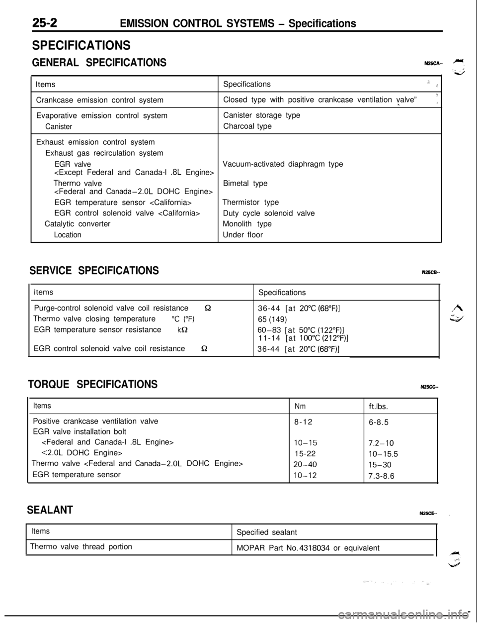
EMISSION CONTROL SYSTEMS - Specifications
SPECIFICATIONS
GENERAL SPECIFICATIONSN25CA-ItemsSpecifications
.,:..rCrankcase emission control systemClosed type with positive crankcase ventilation valve”I
‘:Evaporative emission control systemCanister storage type
CanisterCharcoal type
Exhaust emission control system
Exhaust gas recirculation system
EGR valveVacuum-activated diaphragm type
.8L Engine>
Therm0 valveBimetal type
EGR temperature sensor Thermistor type
EGR control solenoid valve
Duty cycle solenoid valve
Catalytic converterMonolith type
LocationUnder floor
SERVICE SPECIFICATIONSN25CB-
ItemsSpecifications
Purge-control solenoid valve coil resistance
&236-44 [at 20°C (68”F)I
Therm0 valve closing temperature“C (“F)65 (149)
EGR temperature sensor resistance
kQ60-83 [at 50°C (122”F)]11-14 [at
100°C (212”F)]EGR control solenoid valve coil resistance
S236-44 [at 20°C (68”F)]
TORQUE SPECIFICATIONSN25CC-
ItemsPositive crankcase ventilation valve
EGR valve installation bolt
.8L Engine>
<2.0L DOHC Engine>
Therm0 valve
EGR temperature sensor
Nmftlbs.8-12
6-8.5
IO-157.2-1015-22
10-15.5
20-4015-30
10-127.3-8.6
SEALANT
Items
Therm0 valve thread portionSpecified sealant
MOPAR Part No.4318034 or equivalent