Page 439 of 1216

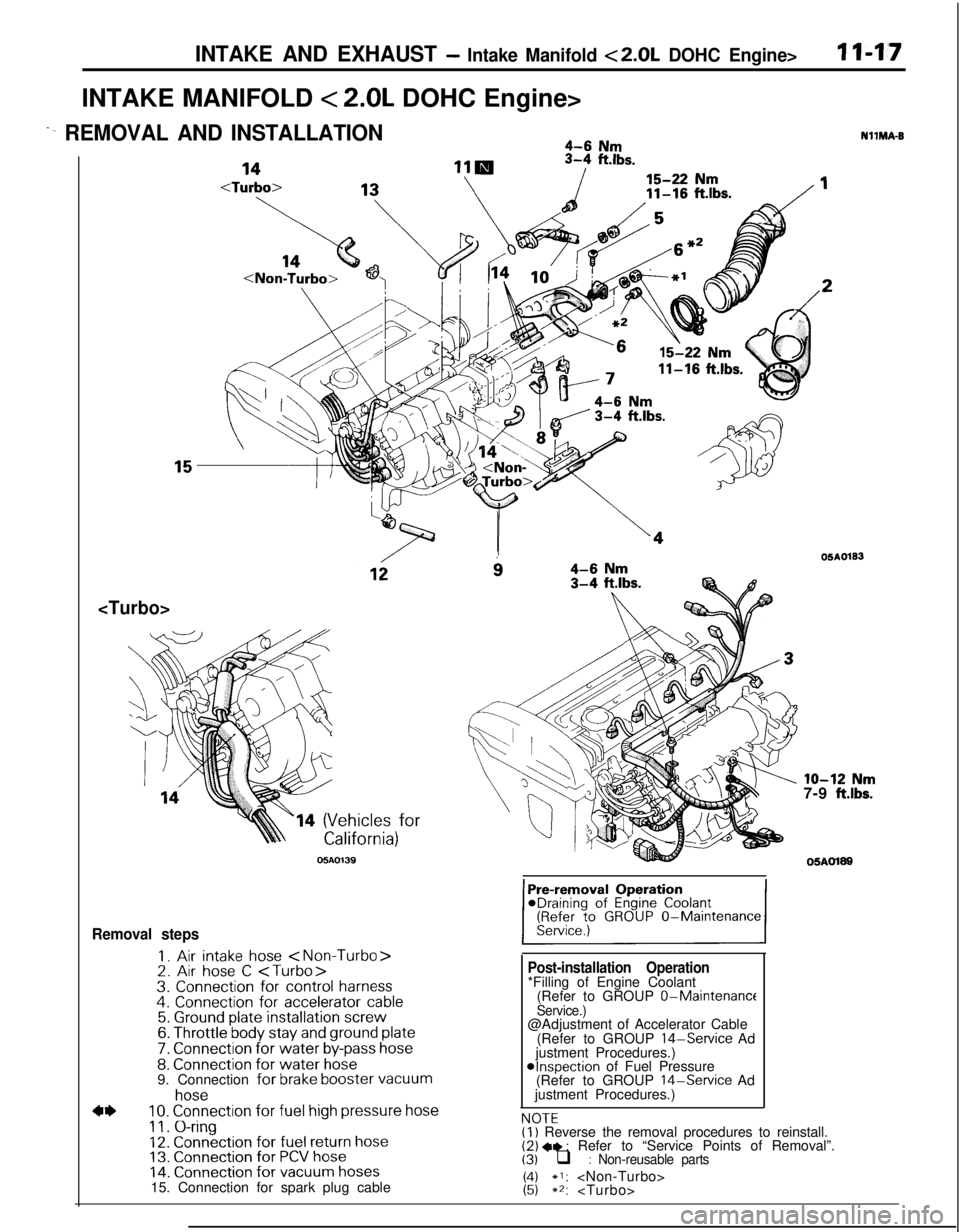
INTAKE AND EXHAUST - Intake Manifold <2.0L DOHC Engine>I I-1.7INTAKE MANIFOLD
< 2.0L DOHC Engine>
^- REMOVAL AND INSTALLATION4-6 Nm
11-16
ft.lbs.
14 (Vehicles for
05AO139
i34-6 Nm3-4 ftlbs.
Removal steps
I. Air intake hose 2. Air hose C 3. Connection for control harness4. Connection for accelerator cable5. Ground plate installation screw6. Throttle body stay and ground plate
7. Connection for water by-pass hose8. Connection for water hose9. Connection for brake booster vacuum
4*
hose10. Connection for fuel high pressure hose
11. O-ring12. Connection for fuel return hose13. Connection for PCV hose14. Connection for vacuum hoses15. Connection for spark plug cable
Post-installation Operation*Filling of Engine Coolant
(Refer to GROUP 0-Maintenance
Service.)@Adjustment of Accelerator Cable
(Refer to GROUP
14-Service Ad
justment Procedures.)
@Inspection of Fuel Pressure
(Refer to GROUP 14-Service Ad
justment Procedures.)
NOTFNllMA-B
OSAO133
lo-12 Nm7-9 ft.lbs.
05AOl89
,.-.-(I) Reverse the removal procedures to reinstall.(2) +e : Refer to “Service Points of Removal”.(3) q : Non-reusable parts
1:;*I: **:
Page 612 of 1216

17-2REAR SUSPENSION - SpecificationsSPECIFICATIONS
GENERAL SPECIFICATIONS
LN17CAA
ItemsVehicles with 1.8L EngineVehicles with 2.0L DOHC
Engine
jSuspension system
3-link, torsion axle with coil spring type
Coil spring
Wire dia.
x O.D. x free length
mm (in.) 10.1 x 105.1 x 336.510.2 x 105.2 x 316.5
(40 x 4.14 x 13.25)(40 x 4.14 x 12.46)
[Coil spring identification color]
[Light Blue
x 11[Orange x 11Spring constant
N/mm
(Ibs./in.) 20 (112.0)23 (128.8)
Shock absorber
TypeHydraulic, cylindrical, double-acting type
Max. length
mm (in.) 495 (19.5)485 (19.1)
Min. length
mm (in.) 315 (12.4)315 (12.4)
Strokemm (in.) 180 (7.1)170 (6.7)Damping force [at 0.3 m/set. (0.9
ft./set.)]
ExpansionN (Ibs.)800 (176)
ContractionN (Ibs.)300 (66)
Wheel bearing
TypeUnit ball bearing
SERVICE SPECIFICATIONS
Items
Standard valueToe-in (Left-right difference)
Camber
LimitWheel bearing end play
Rear hub rotary-sliding resistance
Rear hub rotary-sliding torque
NOTEToe-in and camber cannot be adjusted.mm (in.)
mm (in.)
N (Ibs.)
Nm
(ftlbs.)
TORQUE SPECIFICATIONS
Specifications
0+3 (Of.1 18)
-45’
f 30’
0.01 (004) or less
31
(7) or less
1.8
(1.30) or lessNI’ICB-A
ItemsNmft.lbs.
Wheel bearing nut
Shock absorber upper mounting nut
Shock absorber lower mounting nut
Lateral rod mounting nut (body side)
Lateral rod mounting bolt (axle beam side)
Trailing arm mounting bolt
Piston rod tightening nut
Brake hose and tube bracket mounting bolt
Caliper assembly mounting nut
Rear speed sensor mounting bolt
200-260
40-50
80- 100
80-100
100-120
100-120
20-2517-26
50-609-14144-188
29-36
58-72
58-72
72-87
72-87
14-18
12-19
36-43
I7-10
Nl7CGA
Page 615 of 1216

REAR SUSPENSION - Rear Suspension Assembly17-5
REAR SUSPENSION ASSEMBLYu
-%. REMOVAL AND INSTALLATIONN17GAA
---i
--..17-26 Nm12-19
ft.lbs.9-14 Nm
7- 10 ft.lbs.
Pre-removal Operationl Removal of the Hole Cover(Refer to GROUP 23-Trims.)
Post-installation Operation@Installation of the Hole Cover
(Refer to GROUP
23-Trims.)l Checking and Adiustment of BrakeDisc De‘ilection ’(Refer to GROUP 5-Service Adjust-ment Procedures.)
l Checking and Adjustment of RearDisc Brake Dragging Torque
(Refer to GROUP &Service Adjust-ment Procedures.)
l Parking Brake Lever Stroke Adjust-ment
(Refer to GROUP 5-Service Adjust-ment Procedures.)
Removal steps
W l1. Rear speed sensor
2. Parking brake cable3. Brake hose and tube bracket
4.
Calioer assemblv
200-280 Nm144-168 ftlbs.
llAO293
40-50 Nm
29-36 ltlbs.80-100
Nm*58-72 ft.lbs.*5. Brake disc
’6.Hubcapl +7. Wheel bearing nut8.Tongued washer9. Rear hub bearing unit
10.Dust shield
4*11. Lateral rod mounting bolt (body side)12.Cap
t:
13. Shock absorber upper mounting nut
14. Trailing arm mounting bolt
4*15. Rear suspension assembly
NOTE(I) Reverse the removal procedures to reinstall.
(2) +e : Refer to “Service Points of Removal”.(31 ~~ : Refer to “Service Points of Installation”.
(4) q : Non-reusable parts
(5)
*: Indicates parts which should be temporarily tight-ened, and then fully tightened with the vehicle Inthe unladen condition.12AO336
Page 622 of 1216

17-12REAR SUSPENSION - Torsion Axle and Arm AssemblyTORSION AXLE AND ARM ASSEMBLY
REMOVAL AND INSTALLATIONNl’IPA-.
17-26
Nm12-19 ft.lbs.350-60 Nm2/I
/36-23 ft.lbs./
Nm1’200-260 Nm144-188 ft.lbs.
b1 lA0293
Post-installation Operationl Checking and Adjustment of Brake DiscDeflection
(Refer to GROUP
5-Service AdjustmentProcedures.)achecking and Adjustment of Rear Disc
Brake Dragging Torque
(Refer to GROUP
5-Service AdjustmentProcedures.)
80-100 Nm*58-72 ft.lbs.*
l Parking Brake Lever Stroke Adjustment
(Refer to GROUP 5 -Service AdjustmentProcedures.)
100-120 Nm*72-87 ft.lbs.*4@100-120 Nm*72-87 ft.lbs.*
Removal steps
+I) ++1. Rear speed sensor 2. Parking brake cable
12*0334
l *
3. Brake hose and tube bracket
4. Caliper assembly
5. Brake disc
6. Hub cap
e+ 7. Wheel bearing nut
8. Tongued washer
+I) *+ 9. Rear hub bearing unitIO. Dust shield
l 11. Lateral rod mounting bolt (axle beam side)
*I)12. Shock absorber lower mounting bolt
13. Trailing arm mounting bolt
14. Torsion axle and arm assembly
NOTE(I) Reverse the removal procedures to reinstall.(2) ~~ : Refer to “Service Points of Removal”.(3j W+ : Refer to “Service Points of Installation”.(4) m : Non-reusable parts
(51 *: Indicates parts which should be temporarily tight-
ened, and then fully tightened with the vehicle in
the unladen condition.
Page 869 of 1216

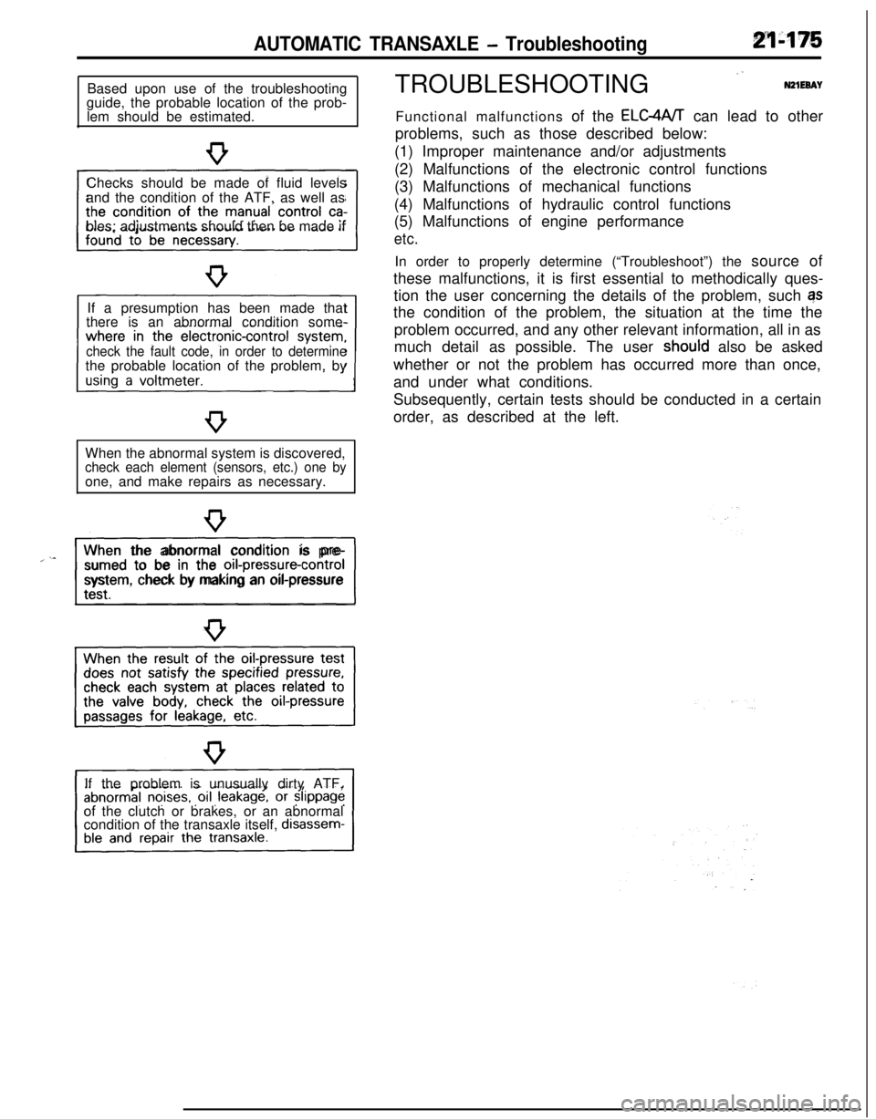
AUTOMATIC TRANSAXLE - TroubleshootingBased upon use of the troubleshooting
guide, the probable location of the prob-
lem should be estimated.
Checks should be made of fluid levels
and the condition of the ATF, as well as
bles; adjustments should then be made if
If a presumption has been made that
there is an abnormal condition some-
check the fault code, in order to determinethe probable location of the problem, by
When the abnormal system is discovered,
check each element (sensors, etc.) one byone, and make repairs as necessary.
“~^II_When the abnormal condition is pre-
sumed to be in the
orI-pressure-controlsystem, check by making an oil-pressure
If the problem is unusually dirty ATF,
of the clutch or brakes, or an abnormal
condition of the transaxle itself,
disassem-TROUBLESHOOTING
”N21EeAYFunctional malfunctions of the ELC4A/T can lead to other
problems, such as those described below:
(1) Improper maintenance and/or adjustments
(2) Malfunctions of the electronic control functions
(3) Malfunctions of mechanical functions
(4) Malfunctions of hydraulic control functions
(5) Malfunctions of engine performance
etc.In order to properly determine (“Troubleshoot”) the source of
these malfunctions, it is first essential to methodically ques-
tion the user concerning the details of the problem, such qs
the condition of the problem, the situation at the time the
problem occurred, and any other relevant information, all in as
much detail as possible. The user
shoutd also be asked
whether or not the problem has occurred more than once,
and under what conditions.
Subsequently, certain tests should be conducted in a certain
order, as described at the left.
Page 1182 of 1216

24-38HEATERS AND AIR CONDITIONING - Compressor
2OAOO87
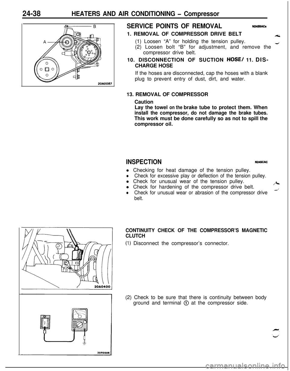
SERVICE POINTS OF REMOVALN248BACa1. REMOVAL OF COMPRESSOR DRIVE BELT
A;i(1) Loosen “A” for holding the tension pulley.
(2) Loosen bolt “B” for adjustment, and remove the
4compressor drive belt.
10. DISCONNECTION OF SUCTION
HOSE/ 11. DIS-
CHARGE HOSE
If the hoses are disconnected, cap the hoses with a blank
plug to prevent entry of dust, dirt, and water.
13. REMOVAL OF COMPRESSOR
Caution
Lay the towel on the brake tube to protect them. When
install the compressor, do not damage the brake tubes.This work must be done carefully so as not to spill the
compressor oil.
INSPECTIONN248CACl Checking for heat damage of the tension pulley.
lCheck for excessive play or deflection of the tension pulley.l Check for unusual wear of the tension pulley.
l Check for hardening of the compressor drive belt.
/J+-
lCheck for unusual wear or abrasion of the compressor drive&’
belt.
CONTINUITY CHECK OF THE COMPRESSOR’S MAGNETIC
CLUTCH
(1) Disconnect the compressor’s connector.
(2) Check to be sure that there is continuity between body
ground and terminal
@ at the compressor side.