Page 921 of 1216
AUTOMATIC TRANSAXLE - Transaxle Assemblv
-MB991 11312K513Pry bar
*Transaxle
llK611
SERVICE POINTS OF REMOVALN2llEAK
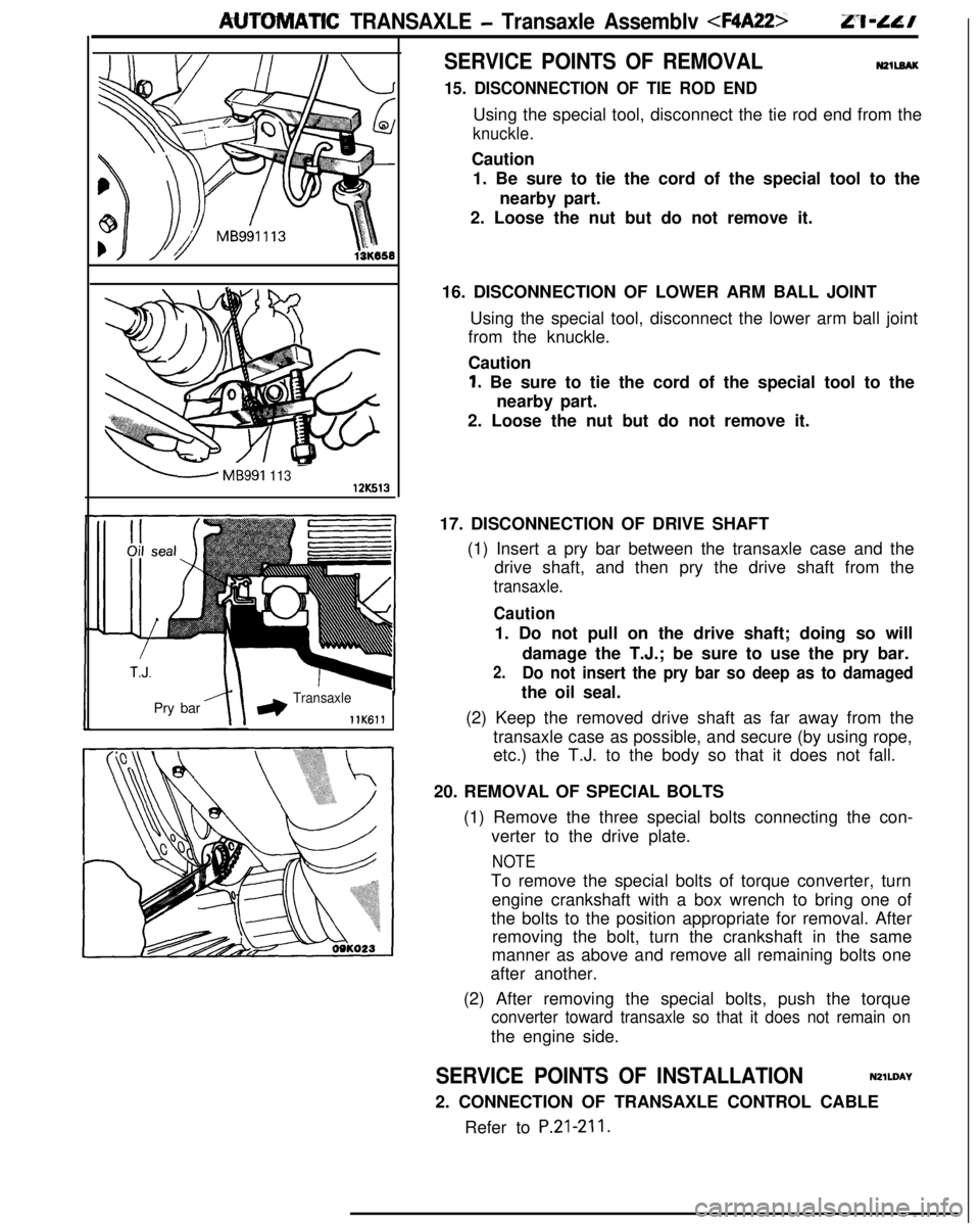
15. DISCONNECTION OF TIE ROD ENDUsing the special tool, disconnect the tie rod end from the
knuckle.Caution
1. Be sure to tie the cord of the special tool to the
nearby part.
2. Loose the nut but do not remove it.
16. DISCONNECTION OF LOWER ARM BALL JOINT
Using the special tool, disconnect the lower arm ball joint
from the knuckle.
Caution
1. Be sure to tie the cord of the special tool to the
nearby part.
2. Loose the nut but do not remove it.
17. DISCONNECTION OF DRIVE SHAFT
(1) Insert a pry bar between the transaxle case and the
drive shaft, and then pry the drive shaft from the
transaxle.
Caution1. Do not pull on the drive shaft; doing so will
damage the T.J.; be sure to use the pry bar.
2.Do not insert the pry bar so deep as to damagedthe oil seal.
(2) Keep the removed drive shaft as far away from the
transaxle case as possible, and secure (by using rope,
etc.) the T.J. to the body so that it does not fall.
20. REMOVAL OF SPECIAL BOLTS
(1) Remove the three special bolts connecting the con-
verter to the drive plate.
NOTETo remove the special bolts of torque converter, turn
engine crankshaft with a box wrench to bring one of
the bolts to the position appropriate for removal. After
removing the bolt, turn the crankshaft in the same
manner as above and remove all remaining bolts one
after another.
(2) After removing the special bolts, push the torque
converter toward transaxle so that it does not remain onthe engine side.
SERVICE POINTS OF INSTALLATIONN2lWAY
2. CONNECTION OF TRANSAXLE CONTROL CABLE
Refer to
P.21-211.
Page 953 of 1216
AUTOMATIC TRANSAXLE - Transaxle Assembly 21-259
TRANSAXLE ASSEMBLY
- REMOVAL AND INSTALLATION N2ll.kB
Pre-removal OperationPost-installation Operation*Removal of Battery*Installation of Air Cleaner, Intercooler and Air Hose@Draining of Transaxle Fluid
A (Refer to GROUP II-Intercooler.)(Refer to GROUP O-Maintenance Service.)
@Removal of Air Cleaner, Intercooler and Air Hose A*Supplying of Transaxle Fluid
(Refer to GROUP O-Maintenance Service.)
(Refer to GROUP II-Intercooler.)*Installation of Battery20-27 Nm
15-19
ft.lbs.
/ IO-14 Nm
43-55 Nm31-40
ft.lbs.
lo-12 Nm
7-9 f?.lbs.
___.Ibs.
lo-12 Nm-7-9 fi.lbs.27-34 Nm20-25
ft.lbs.30-35 Nm
22-25
ft.lbs.
09A0175
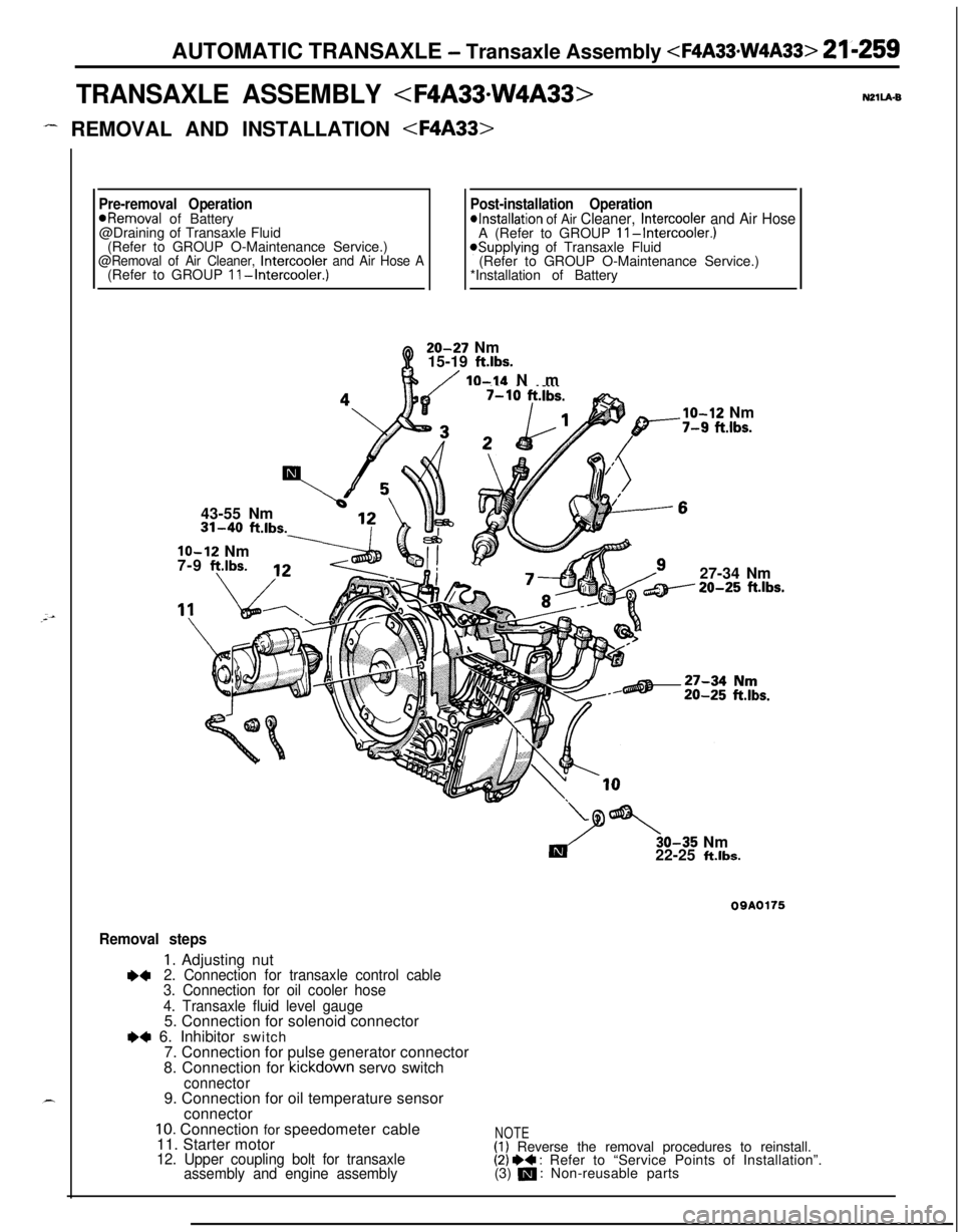
Removal steps
1. Adjusting nut+42. Connection for transaxle control cable
3. Connection for oil cooler hose
4. Transaxle fluid level gauge5. Connection for solenoid connector
e+ 6. Inhibitor switch
7. Connection for pulse generator connector
8. Connection for kickdown servo switch
connector9. Connection for oil temperature sensor
connector
10. Connection for speedometer cable
11. Starter motor
12. Upper coupling bolt for transaxle
assembly and engine assembly
NOTE(1) Reverse the removal procedures to reinstall.(2) I)+ : Refer to “Service Points of Installation”.
(3) m : Non-reusable parts
Page 955 of 1216
AUTOMATIC TRANSAXLE - Transaxle Assembly 21 kz6’1
REMOVAL AND INSTALLATION N2llA-C
(Refer to GROUP
II-Intercooler.)43-55 Nm
\i 513 \20-27 Nm
Q15-19 ft.lbs.
lo-14 NmIO-12 Nm10 ft.lbs.7-9 ftlbs.
/27-34 Nm
ft.lbs.
Y
Es.
Removal steps1. Adjusting nut
l 42. Connection for transaxle control cable3. Connection for oil cooler hose
4. Transaxle fluid level gauge5. Connection for solenoid connector
l +6. Connection for inhibitor switch connector7. Connection for pulse generator connector8. Connection for kickdown servo switch
connector9. Connection for oil temperature sensor
OQAOl63connector
10. Connection for speedometer cable11. Starter motor12. Upper coupling bolt for transaxle
assembly and engine assembly
irkeverse the removal procedures to reinstall.
(2) I)+ : Refer to “Service Points of Installation”
(3) m : Non-reusable parts
Page 1040 of 1216
5 22-2WHEELS AND TIRES - Specifications
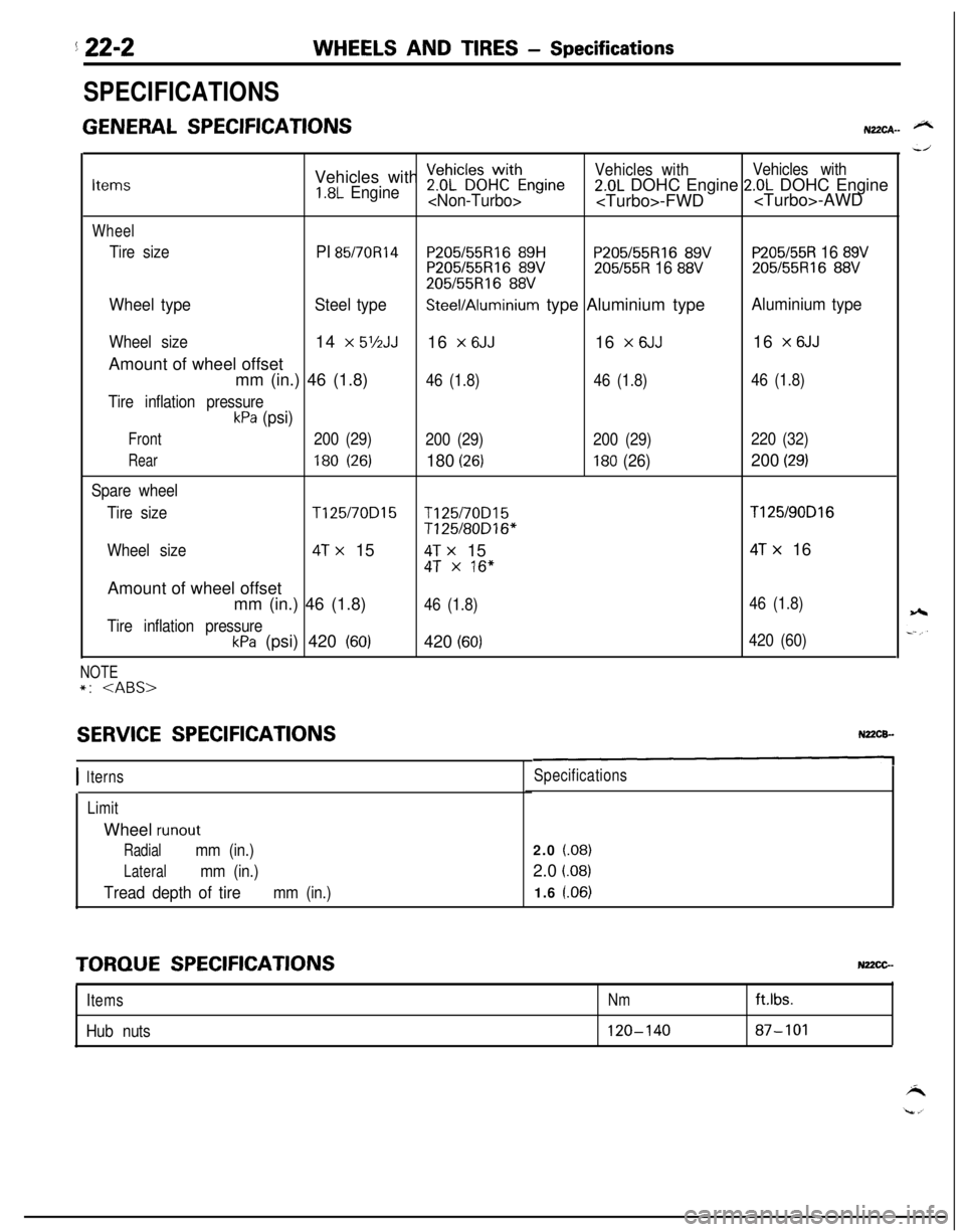
SPECIFICATIONS
GENERAL SPECIFICATIONSN22CA- @NVehicles with
~eDhL”~~HWCthEngineVehicles withVehicles withItems1.8L Engine2.0L DOHC Engine 2.0L DOHC Engine-FWD-AWD
Wheel
Tire sizePI 85/70R14P205155Rl6 89HP205/55R16 89VP205/55R 16 89VP205155R16 89V205/55R 16 88V205/55R16 88V
205/55R16 88V
Wheel typeSteel typeSteel/Aluminium type Aluminium typeAluminium type
Wheel size14 x 5’/2JJ16 x 6JJ16 x 6JJ16 x 6JJAmount of wheel offset
mm (in.) 46 (1.8)
46 (1.8)46 (1.8)46 (1.8)
Tire inflation pressure
kPa (psi)
Front200 (29)
200 (29)200 (29)220 (32)
Rear180 (26)180 (26)180 (26)200 (29)
Spare wheel
Tire size
T125/70D15T125/70D15T125/90D16
T125/80D16*
Wheel size
4T x 154T x 154T x 16
4T x 16”Amount of wheel offset
mm (in.) 46 (1.8)
46 (1.8)46 (1.8)
Tire inflation pressure
kPa (psi) 420 (60)420 (60)420 (60)
NOTE*:
SERVICE SPECIFICATIONS
I 1terns
LimitWheel
runout
Radialmm (in.)
Lateralmm (in.)
Tread depth of tiremm (in.)
Specifications2.0
(.08)2.0
i.08)1.6 l.06)
TORQUE SPECIFICATIONSNz2cG-
ItemsNm
Hub nuts120-140ftlbs.87-101
Page 1145 of 1216
24-l
HEATERS ANDAIR CONDITIONING
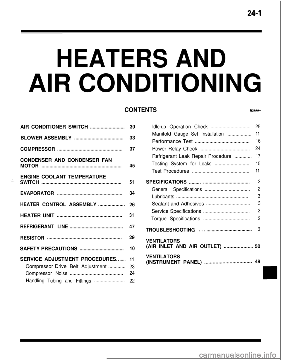
CONTENTSN24M--AIR CONDITIONER SWITCH
..........................30BLOWER ASSEMBLY
.....................................33
COMPRESSOR.................................................37CONDENSER AND CONDENSER FAN
MOTOR............................................................45ENGINE COOLANT TEMPERATURE
-‘-.,SWITCH............................................................51
EVAPORATOR.................................................
34
HEATERCONTROLASSEMBLY....................
26HEATER UNIT
.................................................31
REFRIGERANTLINE........................................47
RESISTOR........................................................29SAFETY PRECAUTIONS
.................................10SERVICE ADJUSTMENT PROCEDURES..
.....11Compressor Drive
Belt Adjustment
.............
23
CompressorNoise........................................24
Handling
TubingandFittings.......................22Idle-up
OperationCheck..............................25Manifold
GaugeSetInstallation..................11Performance Test
.........................................16Power Relay Check
......................................24Refrigerant Leak Repair Procedure
.............17
TestingSystemforLeaks...........................15Test Procedures
...........................................11
SPECIFICATIONS.............................................2
General Specifications..................................2
Lubricants......................................................3Sealant and Adhesives
.................................3Service Specifications
...................................2
TorqueSpecifications...................................2
TROUBLESHOOTING. . . ..a................................3
VENTILATORS(AIR INLET AND AIR OUTLET)
..,....s............. 50
VENTILATORS(INSTRUMENT PANEL)
..,...................*...........49
Page 1146 of 1216
24-2HEATERS AND AIR CONDITIONING - Specifications
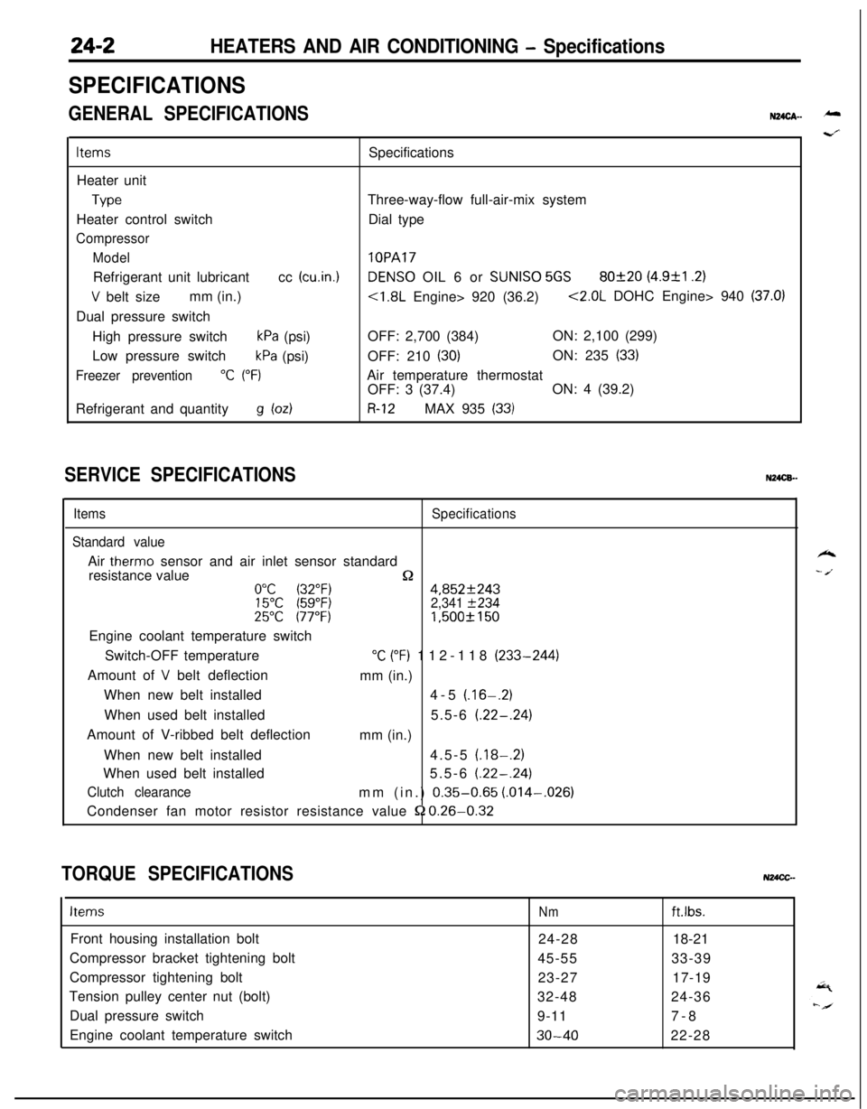
SPECIFICATIONS
GENERAL SPECIFICATIONSN24cA- -
ItemsSpecifications
Heater unit
TypeThree-way-flow full-air-mix system
Heater control switchDial type
Compressor
Model
lOPARefrigerant unit lubricantcc
(cu.in.1DENS0 OIL 6 or SUNISO 5GS80f20 (4.9&l .2)
V belt sizemm (in.)<1.8L Engine> 920 (36.2)<2.0L DOHC Engine> 940 (37.0)Dual pressure switch
High pressure switch
kPa (psi)OFF: 2,700 (384)ON: 2,100 (299)
Low pressure switch
kPa (psi)OFF: 210 (30)ON: 235 (33)
Freezer prevention“C (“F)Air temperature thermostat
OFF: 3 (37.4)ON: 4 (39.2)
Refrigerant and quantity
g bdR-12MAX 935 (33)
SERVICE SPECIFICATIONSN24CB.-
ItemsSpecifications
Standard valueAir
therm0 sensor and air inlet sensor standard
resistance value
n0°C (32°F)4,852f24315°C (59°F)2,341 f23425°C 177°F)1,500f 150Engine coolant temperature switch
Switch-OFF temperature
“C (“F) 112-118 (233-244)
Amount of
V belt deflection
mm (in.)
When new belt installed4-5
(.16-.2)When used belt installed5.5-6
(.22-.24)Amount of V-ribbed belt deflection
mm (in.)
When new belt installed4.5-5
(.18-.2)When used belt installed5.5-6
(.22-.24)
Clutch clearancemm (in.) 0.35-0.65 (.014-,026)
Condenser fan motor resistor resistance value
52 0.26-0.32
TORQUE SPECIFICATIONSN24CC-
ItemsNmft.lbs.Front housing installation bolt
24-2818-21
Compressor bracket tightening bolt
45-5533-39
Compressor tightening bolt
23-2717-19
Tension pulley center nut (bolt)
32-4824-36
Dual pressure switch
9-117-8
Engine coolant temperature switch
30-4022-28
k
- /.
Page 1147 of 1216
HEATERS AND AIR CONDITIONING - Specifications/Troubleshooting24-3LUBRICANTS
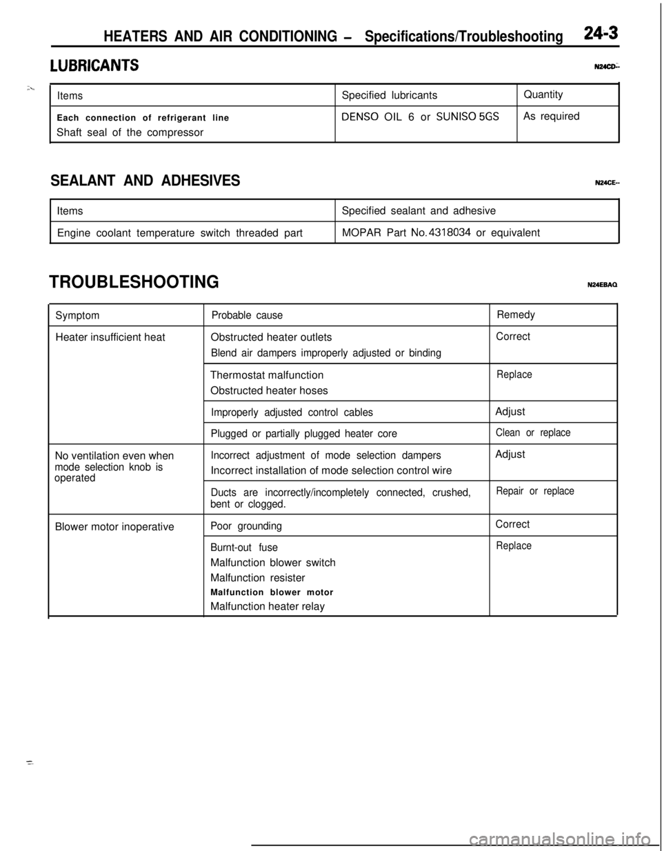
u24as-
;xiItemsSpecified lubricantsQuantity
Each connection of refrigerant lineDENS0 OIL 6 or
SUNISO 5GSAs required
Shaft seal of the compressor
SEALANT AND ADHESIVES, Items
Engine coolant temperature switch threaded partSpecified sealant and adhesive
MOPAR Part No.4318034 or equivalentN24CE-
TROUBLESHOOTINGN24EBAQ
SymptomHeater insufficient heat
No ventilation even when
mode selection knob is
operatedBlower motor inoperative
Probable causeObstructed heater outlets
Blend air dampers improperly adjusted or bindingThermostat malfunction
Obstructed heater hoses
Improperly adjusted control cables
Plugged or partially plugged heater core
Incorrect adjustment of mode selection dampersIncorrect installation of mode selection control wire
Ducts are incorrectly/incompletely connected, crushed,
bent or clogged.
Poor grounding
Burnt-out fuseMalfunction blower switch
Malfunction resister
Malfunction blower motor
Malfunction heater relay
Remedy
Correct
ReplaceAdjust
Clean or replaceAdjust
Repair or replace
Correct
Replace
Page 1149 of 1216
HEATERS AND AIR CONDITIONING - Troubleshooting24-5
From previoys page.
When the resistance of the air-
therm0 sensor is measured[with the air conditioner switch
OFF and when the ambient
temperature of the
air-therm0sensor is
25°C (77“F)], is the
measured resistance approx.
1.5f0.15 kP?
INoMalfunction of tha air-therm0Refer to P.24-6.-sensor.
Refer to P.24-6.
1Yes
When the resistance of the air-
inlet sensor is measured [with the
air conditioner switch OFF andwhen the ambient temperature of
the air-inlet sensor is 25°C (77”F)l
is the measured resistanceapprox.
1.5f0.15 k&2?I
1 Yes
Does idle-up occur immediatelyNo Malfunction of the DC motor
after the air conditioner switch is
cl800 Engine>
switched ON?Malfunction of the stepper motor
Yes~2000 DOHC Engine>
Malfunction of the MPI control unit
* Malfunction of the air conditioner
control unit.Refer to P.24-6.