Page 734 of 1216

21-40 MANUAL TRANSAXLE - Transaxle Assembly Amount
1-2 mm
J
33. INSTALLATION OF OIL SEALInstall the drive shaft oil seal using the special tool.
.‘p,
/
27. INSTALLATION OF OIL GUIDEInstall the oil guide to the transaxle case as illustrated.
26. INSTALLATION OF TRANSAXLE CASE(1) Place the selected spacers on the intermediate gear
and the differential’s bearing outer race. Also insert the
selected spacer between the output shaft bearing outerrace and the transaxle case.
(2) Set so that the threaded hole of the reverse idler gear
hshaft’s head is facing in the direction indicated in the
.-
illustration.
NOTEIf there is a great deviation in the direction in which the
threaded hole is facing, it will be impossible to align thethreaded hole and the hole in the case after the
transaxle case is installed.
(3) Apply specified sealant to the clutch housing side of the
transaxle case.
Specified sealant: MITSUBISHI Genuine
Part No.
MD997740
or equivalent
Caution
Squeeze out sealant from the tube uniformly with-
out excess or discontinuity.(4) Install the transaxle case onto the clutch housing.
(5) Insert a Phillips screwdriver
18 mm (32 in.) shaft
diameter] into the bolt hole in the case, as shown in thefigure, and use it to align the threaded hole of the
reverse idler gear shaft with the bolt hole in the
transaxle case.(6) Install the reverse idler gear shaft bolt and tighten the
bolt by fingers.
(7) Tighten the all transaxle tightening bolts to specified
*
torque.,-(8) Tighten the reverse idler gear shaft bolt to specified
torque.
Page 741 of 1216

MANUAL TRANSAXLE -Input Shaft Assembly
lamiNear20105:
Springprotrusion2010018TFM0021
MD998320/
SPEED GEARS
lCheck the bevel gear and clutch gear teeth for damage and
wear.l Check the synchronizer cone for rough
surface, damage
and wear.
lCheck the gear ‘bore and front and rear ends for damage
and wear.
SERVICE POINTS OF REASSEMBLY
12. INSTALLATlON OF SYNCHRONIZER SPRING
Install the synchronizer spring so that its protrusion fits intothe groove in the synchronizer key. Make sure that the
protrusions in the front and rear springs are not in the
groove of the same key.
11. INSTALLATION OF 3RD-4TH SPEED SYNCHRONIZER
ASSEMBLY(1) Install the synchronizer assembly so that the part that
has the small round indentation is in the oil groove at
the hub end.
NOTEIf the installation is in the opposite way, press-in might
not be possible. This is because the edge of the hub
inner diameter
spline at the part that has the small
round indentation is made to facilitate pressing in.
(2) Press the
3rd-4th speed synchronizer assembly onto
the input shaft using the special tool as illustrated.
Caution
When installing the synchronizer assembly, make
sure that three synchronizer keys are seated cor-rectly in respective grooves of the synchronizer
ring.(3) Check the
3rd speed gear rotates smoothly.
9. INSTALLATION OF BEARING SLEEVEUse the special tool as illustrated.
Page 743 of 1216
MANUAL TRANSAXLE -Input Shaft Assemblv 21-49
20105t
2. INSTALLATION OF BALL BEARING
Install the ball bearing over the input shaft using the sdecial
tool..e,*
1.INSTALLATION OF SNAP RINGSnap rings are available in three different thickness. Select
the thickest one that fits in the snap ring groove.
CautionDo not cause damage to the input shaft oil seal
contacting portion.Standard value: 0.01-0.12 mm
(.0004-,005 in.)
Page 747 of 1216

MANUAL TRANSAXLE -Incut Shaft Assembly
Key
2010018
2ndgearTFM0024
MD998320
20105f
SPEED GEARS
lCheck the bevel gear and clutch gear teeth for damage andw.wear.l Check the synchronizer cone for rough surface, damage
and wear.
lCheck the gear bore and front and rear ends for damage
and wear.
SERVICE POINTS OF REASSEMBLY
13. INSTALLATION OF SYNCHRONIZER SPRINGAssemble the synchronizer spring so that its projection
may be engaged in the groove of the synchronizer key.
Take care to prevent the projections of the front and rear
spring from sitting in the groove of the same key.
12. INSTALLATION OF 3RD-4TH SPEED SYNCHRONIZER
ASSEMBLY
(1) Install the synchronizer assembly so that the part that
has the small round indentation is in the oil groove at
the hub end.
NOTEIf the installation is in the opposite way, press-in might
not be possible. This is because the edge of the hub
inner diameter spline at the part that has the small
round indentation is made to facilitate pressing in.
(2) Press the
3rd-4th speed synchronizer assembly onto
the input shaft using the special tool as illustrated.
Caution
When installing the synchronizer assembly, make
sure that three synchronizer keys are seated cor-rectly in respective grooves of the synchronizer
ring.(3) Check the
3rd speed gear rotates smoothly.
10. INSTALLATION OF BEARING SLEEVEUse the special tool as illustrated.
j
Page 759 of 1216

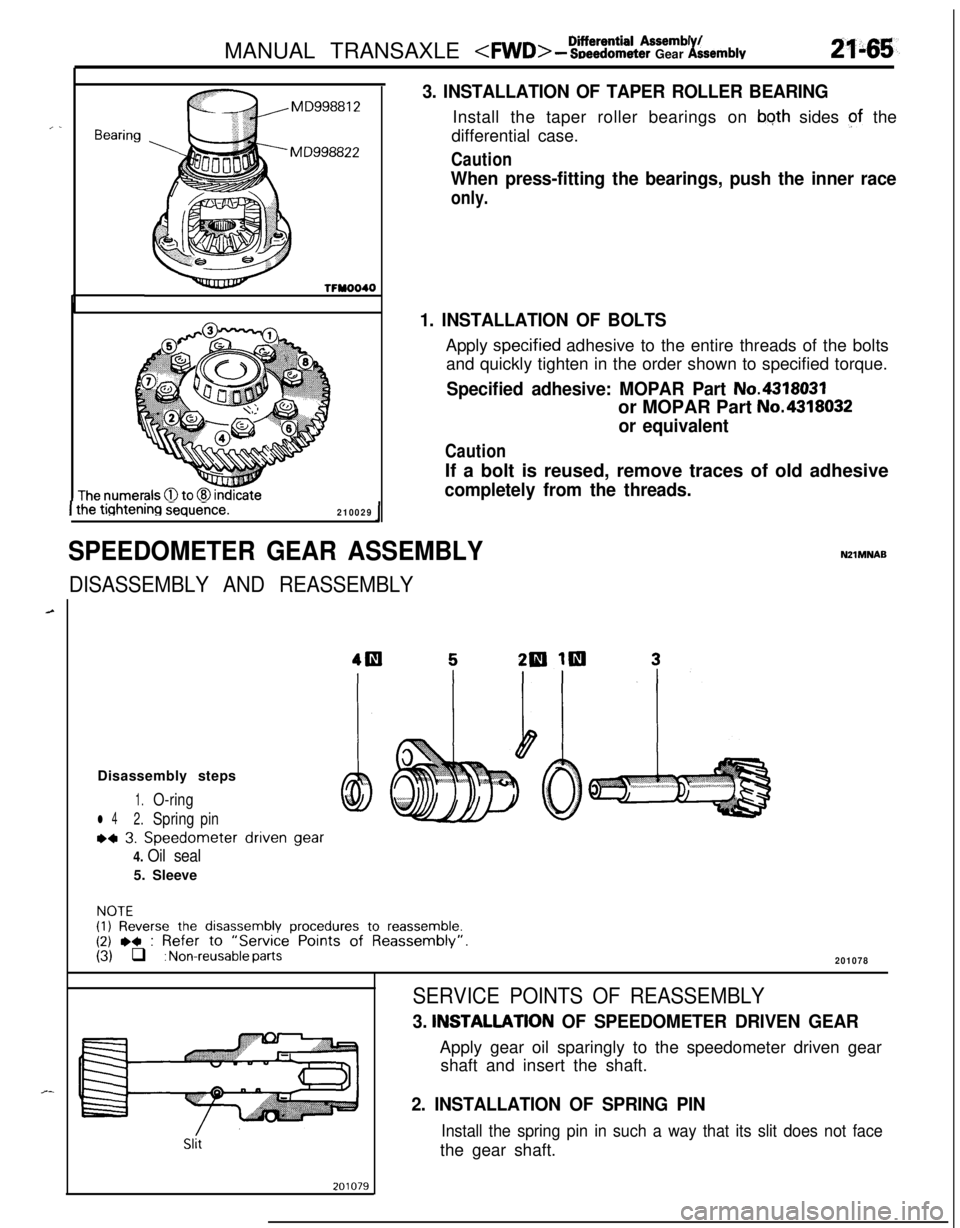
bierential Assembl /MANUAL TRANSAXLE - SDeedometer Gear ksemblv
, .Bearing
TFYOOIO
The numerals 0 to (8 indicate1 the tiqhtening Gequeice.210029I
SPEEDOMETER GEAR ASSEMBLY
3. INSTALLATION OF TAPER ROLLER BEARINGInstall the taper roller bearings on
bqth sides of the
differential case.
Caution
When press-fitting the bearings, push the inner race
only.
1. INSTALLATION OF BOLTSApply
spec.ified adhesive to the entire threads of the bolts
and quickly tighten in the order shown to specified torque.
Specified adhesive: MOPAR Part No.4318031or MOPAR Part
No.4318032
or equivalent
CautionIf a bolt is reused, remove traces of old adhesive
completely from the threads.
DISASSEMBLY AND REASSEMBLY
NZlMNABDisassembly steps
1.O-ring
l 42.Springpin
~4 3. Speedometer driven gear
4. Oil seal5. Sleeve
NOTE(1) Reverse the disassembly procedures to reassemble.(2) ,+ : Refer to “Service Points of Reassembly”.(3) q : Non-reusable parts201078
Slit
SERVICE POINTS OF REASSEMBLY
3. INSTALLATlON OF SPEEDOMETER DRIVEN GEARApply gear oil sparingly to the speedometer driven gear
shaft and insert the shaft.
2. INSTALLATION OF SPRING PIN
Install the spring pin in such a way that its slit does not facethe gear shaft.
Page 760 of 1216
21-66MANUAL TRANSAXLE - Clutch Housing Assembly
CLUTCH HOUSING ASSEMBLYNZlMPAL
DISASSEMBLY AND REASSEMBLY
2=
-,_
1
L--15-22 Nm
11-15 ftlbs.
20-27 Nm15-19 ft.lbs.
Disassembly steps
1.Bolt2. Select lever assembly
3. Select lever shoe
4. Interlock place bolt
5.Gasket+e l *6. Lock pinj\l * l *7. Spring pin
8. Neutral return spring
9.Stopper body10.Control finger11.Interlock plate
12. Neutral return spring assembly
13.Control shaft14. Control shaft boot
l 415.Oil seal
2100019
l * 16. Needle bearing
l a 17. Needle bearing;EJ. Fil;tch housing
20: Return spring
21. Stopper plate
22. Spring pin
NOTE(1) Reverse the disassembl procedures to reassemble.(2)~~ : Refer to “Service ornts of Disassembly”.6.(3)l + : Refer to “Service Points of Reassembly”.(4) q : Non-reusable parts
Page 761 of 1216

MANUAL TRANSAXLE - Clutch Housing Assembly
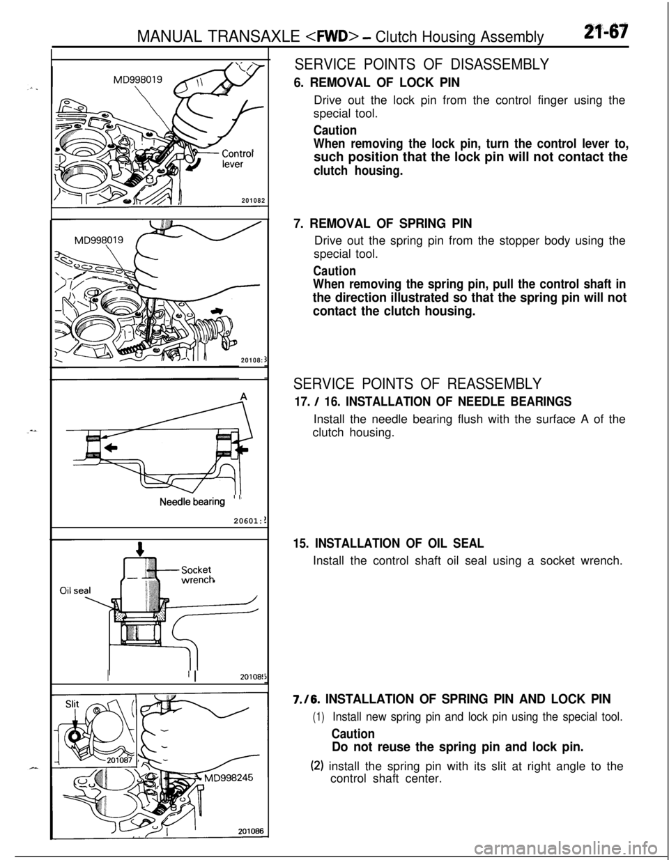
SERVICE POINTS OF DISASSEMBLY
2f-67
MD998019
\
\
- Control
J$p--lever
201082
MD998\�w
-
20108:
Needle bearing’ ’
20601:
Socketwrench
I’ I20108!
6. REMOVAL OF LOCK PINDrive out the lock pin from the control finger using the
special tool.
Caution
When removing the lock pin, turn the control lever to,such position that the lock pin will not contact the
clutch housing.
7. REMOVAL OF SPRING PINDrive out the spring pin from the stopper body using the
special tool.
Caution
When removing the spring pin, pull the control shaft in
the direction illustrated so that the spring pin will not
contact the clutch housing.
SERVICE POINTS OF REASSEMBLY
17. / 16. INSTALLATION OF NEEDLE BEARINGSInstall the needle bearing flush with the surface A of the
clutch housing.
15. INSTALLATION OF OIL SEALInstall the control shaft oil seal using a socket wrench.7./6.
INSTALLATION OF SPRING PIN AND LOCK PIN
(1)Install new spring pin and lock pin using the special tool.
Caution
Do not reuse the spring pin and lock pin.
(2) install the spring pin with its slit at right angle to the
control shaft center.
Page 763 of 1216

MANUAL TRANSAXLE 2 S~ecifCca?io’iik
2f.46g
\ ,...,
,,, .,
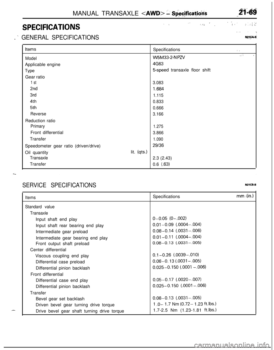
SPECIFICATIONS
1 L,‘S. / ,‘; ,< ’,f. : ,: ; .>r
“. . ..&
. ’ GENERAL SPECIFICATIONSNZ1.pA.B’
Items
ModelApplicable engine
TypeGear ratio
1 st
2nd
3rd
4th
5th
ReverseReduction ratio
PrimaryFront differential
TransferSpeedometer gear ratio (driven/drive)
Oil quantity
Transaxle
TransferSpecifications
(I
W5M33-2-N PZV.,A I
4G63
5-speed transaxle floor shift
3.083
I .684
1.115
0.833
0.666
3.166
1.275
3.866
1.090
29136lit.
(qts.)2.3 (2.43)
0.6
l.63)
SERVICE SPECIFICATIONSN21CB-B
d-...
Items
Standard value
TransaxleInput shaft end play
Input shaft rear bearing end play
Intermediate gear preload
Intermediate gear bearing end play
Front output shaft preload
Center differential
Viscous coupling end play
Differential case preload
Differential pinion backlash
Front differential
Differential case end play
Differential pinion backlash
TransferBevel gear set backlash
Driven bevel gear turning drive torque
Drive bevel gear shaft turning drive torqueSpecifications
o-0.05 (O-.002)
0.01-0.09 (.0004-,004)
0.08-0.14 (.0031-,006)
0.01-0.11 (.0004-,004)
0.08-0.13 (.0031-,005)
0.1-0.26 (.0039-.OlO)0.08-O. 13
LOO31 - ,005)
0.025-0.150 LOO01 -.006)
0.05-0.17 (.0020-,007)
0.025-0.150 (.OOOl-,006)
0.08-0.13 (.0031-.005)
1
.O- 1.7 Nm (0.72- 1.23 ft.lbs.11.7-2.5 Nm (1.23-1.81
ft.lbs.1
mm,.(in.)