Page 144 of 1216

5-4BRAKES - Specifications
SERVICE SPECIFICATIONS
NO5CB-
ItemsSpecifications
Standard value
Brake pedal heightmm (in.) 176-181 (6.9-7.1)
Brake pedal free playmm (in.) 3-8
(l-.3)Brake pedal to floorboard clearance
mm (in.) 80 (3.1) or more
Parking brake lever stroke
5-7 notches
Output pressure proportioning valve
MPa (psi)
Split point
3.95-4.45 (561-633)
3.45-3.95 (491-561)
Output pressure [input pressure]
5.15-5.65 (732-804) [8.2 (1 ,I 63)l
4.65-5.15 (661-732) (7.7 (1,095)1Disc brake dragging force at hub bolt
N (Ibs.) [Nm (ftlbs.)]70 (15) or less [4 (3) or less1Booster push rod to master cylinder piston clearance
mm (in.)
9 inch brake booster
0.8-l .O (.031-,039)
7
+8 inch brake booster0.5-0.7 (.020-.028)
Speed sensor’s internal resistance
kQ 0.8-l .2*
Clearance between the speed pole piece and
the toothed rotor
mm (in.)
0.3-0.9 (.012-,035)”Limit
Left/right proportioning valve out pressure difference
MPa (psi)0.4 (57)
Disc brake pad thickness
mm (in.) 2.0 (08)
Front disc thickness
mm (in.) 22.4 (882)
Rear disc thickness
mm (in.) 8.4
(.331)Disc
runoutmm (in.) 0.08 (.0031)Hub end play
mm (in.) 0.008
(.00031)
NOTE
*: Vehicles with ABS
TORQUE SPECIFICATIONS
ItemsNmft.lbs.
Pedal support bracket installation bolts
8-12
6-9
Pedal support bracket installation nut
IO-157-11
Pedal rod to pedal support bracket
17-26
12-19
Pedal rod to clutch pedal bracket
17-26
12-19
Clutch pedal bracket installation bolt
8-12
6-9
Turn-over spring mounting bolt
17-26
12-19
Stop lamp switch mounting nut
IO-157-l 1‘Clutch master cylinder installation nuts
10-157-11
Clutch pedal installation nut
20-2514-18
Lever assembly (A) installation nut
20-2514-18
Lever assembly
(B) installation nut20-2514-18
Page 145 of 1216

BRAKES - Specifications5-5Items
Nmftlbs.Master cylinder to brake booster
8-126-9
Piston stopper bolt
1.5-3.0l-2Nipple installation screw
1.5-3.0l-2Brake booster installation nuts
11-178-12
Fitting15-1811-13
Flared brake line nuts
13-179-12
Brake hose bracket installation bolts
17-2612-19
Front disc brake assembly installation bolts
80-10058-72
Lock pin (front)
64-8646-62
Guide pin (front)
64-8646-62
Bleeder screw
7-95-7
Wheel bearing nut
200-260144-188
Dust shield to axle beam
9-14
7-10Rear disc brake assembly installation bolts
50-6036-43
Drive shaft to companion flange
55-6539-47
companion flange to rear axle shaft160-200116-159
Brake hose to caliper body (rear)
25-35
18-25Lock
pin (rear)
22-3216-23
Guide pin (rear)
22-32
16-23Spindle lever to parking brake lever
40-5529-40
3ear speed sensor installation bolt
9-147-10Speed sensor bracket installation bolt
9-14
7-10
3otor to front hub
7-115-8
3otor to rear hub
9-147-10
LUBRICANTSNO5CP-
ItemsBrake fluidSpecified lubricant
MOPAR Brake
Fluid/Conforming to
DOT3Brake pedal bushing inner surface
Clevis pin and washer
Parking brake lever sliding parts
Bushing inner surfaceMOPAR Multi-mileage Lubricant
Part No. 2525035 or equivalent
Page 146 of 1216
5-6BRAKES - Specifications/Special Tools
ItemsBrake piston seal
Brake piston boot inner surfaces
Brake lock pin boot inner surfaces
Guide pin boot inner surfaces
Guide pin and caliper support contact surface
Lock pin and caliper support contact surface
Spindle lever, lever boot, connecting link,
O-ring and auto adjuster spindle
SPECIAL TOOLSSpecified lubricant
Repair kit grease (orange)
Rear disc brake
Pressing of the rear disc brake pistons
Sliding hammer set
Page 231 of 1216

6-I
CLUTCH
CONTENTS
CLUTCH CONTROL. . . . . . . . . . . . . . . . . . . . . . . . . . . . . . . . . . . . . . . . .9SPECIFICATIONS. . . . . . . . . . . . . . . . . . ..m........................2
GeneralSpecifications..................................2CLUTCH COVER AND DISC..........................16Lubricants......................................................3
CLUTCH MASTER CYLINDER........................11Service Specifications...................................2Torque Specifications
...................................3
CLUTCH PEDAL..............................................7
TROUBLESHOOTING. . . . . . . . . . . . . . . . . . . . . . . ..*............4
CLUTCHRELEASE CYLINDER . . . . . . . ..a.............13Clutch chatters
SERVICE ADJUSTMENT PROCEDURES . . . . . . .5Clutch noise
Bleeding. . . . . . . . . . . . . . . . . . . . . . . . . . . . . . . . . . . . . . . . . . . . . . . . . . . . . . . .6Clutch pedal feels “heavy”
Clutch Pedal Inspection and Adjustment . . . .
5Clutch slips
SPECIAL TOOL,.,#mmm,.*......B......................*........3Gear shift malfunctionCAUTIONWhen
servicing clutch assemblies or com-
ponents for vehicles with 1.8L engine, doNOT
create dust by sanding or by cleaning
clutch parts with a dry brush or with
compressed air. (A water dampened cloth
should be used). The clutch disc contains
“Asbestos Fibers” which can become air-
borne if dust is created during serviceoperations. Breathing dust containing
“Asbestos Fibers”may cause seriousbodily
harm.
Page 232 of 1216

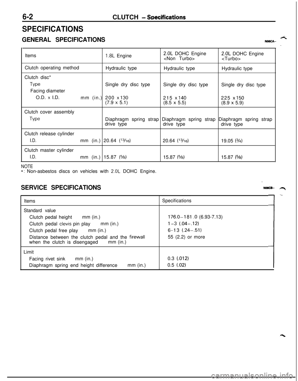
6-2CLUTCH - SDecifications
SPECIFICATIONS
GENERAL SPECIFICATIONS
Items1.8L Engine2.0L DOHC Engine
2.0L DOHC Engine
Clutch operating method
Hydraulic type
Hydraulic type
Hydraulic type
Clutch disc*
TypeSingle dry disc type
Single dry disc type
Single dry disc type
Facing diameter
O.D.
x I.D.
mm (in.) 200 x 130215 x 140225 x 150(7.9 x 5.1)
(8.5 x 5.5)
(8.9 x 5.9)
Clutch cover assembly
TypeDiaphragm spring strap Diaphragm spring strap Diaphragm spring strap
drive type
drive type
drive type
Clutch release cylinder
I.D.mm (in.) 20.64 (13/16)20.64 (13/6)19.05 (3h)Clutch master cylinder
I.D.mm (in.) 15.87 (%)15.87 (%)15.87 (543)
NOTE*: Non-asbestos discs on vehicles with 2.0L DOHC Engine.
SERVICE SPECIFICATIONS
Items
Standard valueClutch pedal heightmm (in.)
Clutch pedal
clevis pin playmm (in.)
Clutch pedal free playmm (in.)
Distance between the clutch pedal and the firewall
when the clutch is disengagedmm (in.)
Limit
Facing rivet sinkmm (in.)
Diaphragm spring end height differencemm (in.)
NO6lX- .H,
Specifications
176.0-I 81 .O (6.93-7.13)
l-3 (.04-.12)6-13 (.24-.51)
55 (2.2) or more
0.3 (012)
0.5
(.02)L-
Page 233 of 1216

CLUTCH - Specifications/Special Tool6-3
TORQUE SPECIFICATIONSNMCC-Items
Nmftlbs.Clutch pedal to clutch pedal support bracket
20-2514-18
Clutch pedal support bracket
8-12
6-9
Clutch pedal support bracket to firewall
10-157-l 1Stop light switch
10-157-11
Brake booster installation nut
11-17
8-12
Master cylinder to firewall
10-157-11
Pedal rod to clutch pedal support bracket
17-2612-19
Clutch pedal bracket
8-l 26-9
Pedal rod to clutch pedal bracket
17-2612-19
Clutch tube flare nut
13-17
9-12
Air cleaner bracket
8-12
6-9
Clutch tube clamp to body
8-l 26-9
Reservoir band
5-7
4-5
Clutch release cylinder
15-22
11-16Clutch release cylinder to union bolt
2518Bleeder plug
9-13
7-9
Fulcrum35-4225-30Clutch cover assembly
15-22
11-16
- LUBRICANTSNOSCD-Items
Contact surface of release bearing and fulcrum of clutch
release fork
Inner surface of clutch release bearing
Inner surface of clutch disc splineSpecified lubricants
MOPAR Multi-mileage Lubricant
Part
No.2525035 or equivalent
Contact portion of release fork to release cylinder push rod
Bushing,
clevis pin, washer and bushing
Inner surface of clutch release cylinder and outer
circumference of piston and cupMOPAR Brake Fluid/Conforming to
DOT3Inner surface of clutch master cylinder and outer
circumference of piston assembly
SPECIAL TOOL
ToolNumber
MD9981 26
NameUse
Clutch disc center
guideClutch disc center hole alignment
\\
Page 249 of 1216

7-l
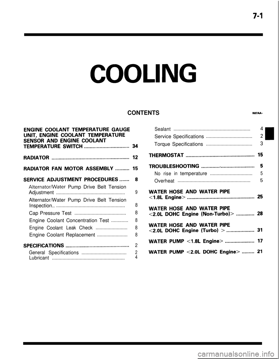
COOLING
CONTENTS
ENGINE COOLANT TEMPERATURE GAUGEUNIT,
ENGINE COOLANT TEMPERATURE
SENSOR AND ENGINE COOLANT
TEMPERATURE SWITCH................................34
RADIATOR.......................................................12
RADIATORFANMOTOR ASSEMBLY..........15
SERVICE ADJUSTMENT PROCEDURES.......8
Alternatormater Pump Drive Belt Tension
Adjustment
....................................................9Alternator/Water Pump Drive Belt Tension
Inspection..
....................................................8Cap Pressure Test
.......................................8Engine Coolant Concentration Test
.............8
EngineCoolantLeakCheck........................8Engine Coolant Replacement
.......................8
SPECIFICATIONS.............................................2
GeneralSpecifications..................................2
Lubricant.......................................................4
Sealant..........................................................4Service Specifications
...................................2Torque Specifications
...................................3THERMOSTAT
.................................................15
TROUBLESHOOTING......................................5
Noriseintemperature................................5
Overheat.......................................................5
WATER HOSE AND WATER PIPE
<1.8L Engine>................................................25
WATER HOSE AND WATER PIPE
<2.0LDOHCEngine(Non-Turbo)>.............28
WATER HOSE AND WATER PIPE
<2.0LDOHCEngine(Turbo)>....................31
WATERPUMP<1.8LEngine>.....................17
WATER PUMP <2.0L DOHC Engine>.........21
Page 250 of 1216

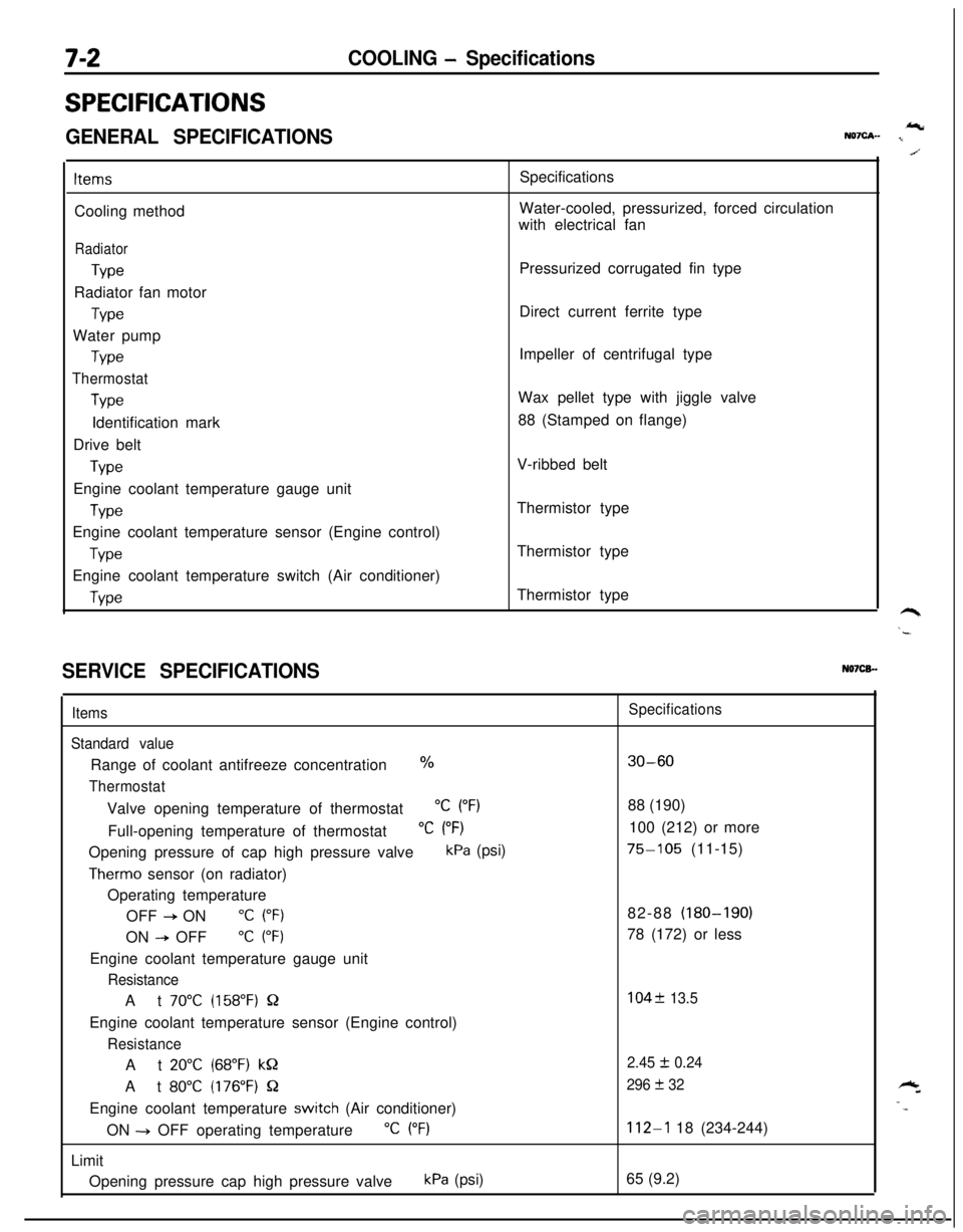
7-2COOLING - Specifications
SPECIFICATIONS
GENERAL SPECIFICATIONSIcNQ7cA- I
ItemsCooling method
Radiator
TypeRadiator fan motor
TypeWater pump
Type
Thermostat
TypeIdentification mark
Drive belt
TypeEngine coolant temperature gauge unit
WeEngine coolant temperature sensor (Engine control)
TypeEngine coolant temperature switch (Air conditioner)
WeSpecifications
Water-cooled, pressurized, forced circulation
with electrical fan
Pressurized corrugated fin type
Direct current ferrite type
Impeller of centrifugal type
Wax pellet type with jiggle valve
88 (Stamped on flange)
V-ribbed belt
Thermistor type
Thermistor type
Thermistor type
SERVICE SPECIFICATIONSN07CB.-
Items
Standard valueRange of coolant antifreeze concentration
%
ThermostatValve opening temperature of thermostat
“C (“F)Full-opening temperature of thermostat
“C (“F)Opening pressure of cap high pressure valve
kPa (psi)
Therm0 sensor (on radiator)
Operating temperature
OFF
+ ON“C (“F)ON
--P OFF“C (“F)Engine coolant temperature gauge unit
ResistanceAt
70°C (158°F) QEngine coolant temperature sensor (Engine control)
ResistanceAt
20°C (68°F) kQAt
80°C (176°F) QEngine coolant temperature
switch (Air conditioner)
ON -+ OFF operating temperature
“C (“F)Limit
Opening pressure cap high pressure valve
kPa (psi)
Specifications
30-6088 (190)
100 (212) or more
75-105 (11-15)
82-88 (180-190)
78 (172) or less
104f 13.5
2.45
I!I 0.24
296
+ 32
112-l 18 (234-244)
65 (9.2)