Page 269 of 1216

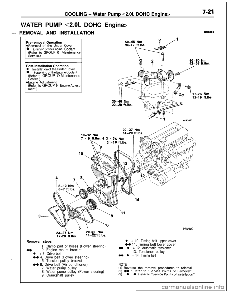
COOLING - Water Pump <2.0L DOHC Engine>7-21WATER PUMP <2.0L DOHC Engine>
--- REMOVAL AND INSTALLATION
No7Ms-B
_Pre-removal Operation
@Removal of the Under Coverl Draining of the Engine Coolant(Refer to GROUP O-MaintenanceService.)
50-65 Nm136-47 ft.lbs.
60-60 Nm
Post-installation Operation
l installation of the Under Coverl supplying of the Engine Coolant(Refer to GROUP O-MaintenanceService.)*Engine Adjustment
(Ri+&; to GROUP g-Engine Adjust-
lo-12 Nm
7-9 ft.lbs. 43-5
31-4
III-40 Nm!-29 ft.lbs.17-26
12-19OlAO560
20-27 Nm14-20 ft.lbs.
23-27 Nm
17-20 ft.lbs.
”20-’ 30 Nm” .““*wY--
-~ . .14-22 ft.ll3s.Removal steps
I. Clamp part of hoses (Power steering)
+*2. Engine mount bracket
l + 3. Drive belte+ 4. Drive belt (Power steering)5. Tension pulley bracket
I)4 6. Drive belt (Air conditioner)7. Water pump pulley
8. Water pump pulley (Power steering)
9. Crankshaft pulley
l + 10. Timing belt upper coverI)4 11. Timing belt lower cover+I) l + 12. Automatic tensioner13. Tensioner pulley
+I) l + 14. Timing belt
NOTE(1) Reverse the removal procedures to reinstall.(2) +e : Refer to “Service Points of Removal”.(3) l 4 : Refer to “Service Points of Installation”
,“k.
Page 276 of 1216
7-28COOLING- Water Hose and Water Pipe <2.0L DOHC Engine (Non-Turbo)>
<2.0L DOHC Engine (Non-Turbo)>
REMOVAL AND INSTALLATION
Post-installgtion Pperation@Supplying of the Engine Coolant(FF$efeet; GROUP O-Maintenance
6
/5
/l--5ia
225-30 Nm
18-22
ft.lbs.
12-1s Nrn9-11 ft.lbs.
Removal steps1 Air intake hose
2. Condenser fan motor assembly
3. Self-locking nut4. Gasket
5. Oxygen sensor harness connector
6. Exhaust manifold cover (A)7. Self-locking nut
8. Engine hanger
04A01059. Exhaust manifold
10. Exhaust manifold gasket11. Exhaust manifold cover(B)
NOTE(1) Reverse the removal procedures to reinstall.(21 m : Non-reusable parts
Page 282 of 1216

7-34 COOLINGWater Hose and Water Pipe <2.0L DOHC Engine (Turbo)>/Engine Coolant Temperature- Gauge Unit. Engine Coolant Temoerature Sensor and Enoine Coolant Temoerature Switch
05A0026
05K55734. INSTALLATION OF WATER HOSE
Install the water hose with the longer straight area
positioned on the turbo side.
27. INSTALLATION OF TURBOCHAGER ASSEMBLY
Clean the alignment surfaces shown in the illustration.
Caution
When cleaning, care must be taken so that a piece of
the gasket does not enter the oil passage hole.
18. INSTALLATION OF WATER PIPE
(B)Before installing to the water inlet pipe, apply machine oil to
the inner surface of the pipe flare.
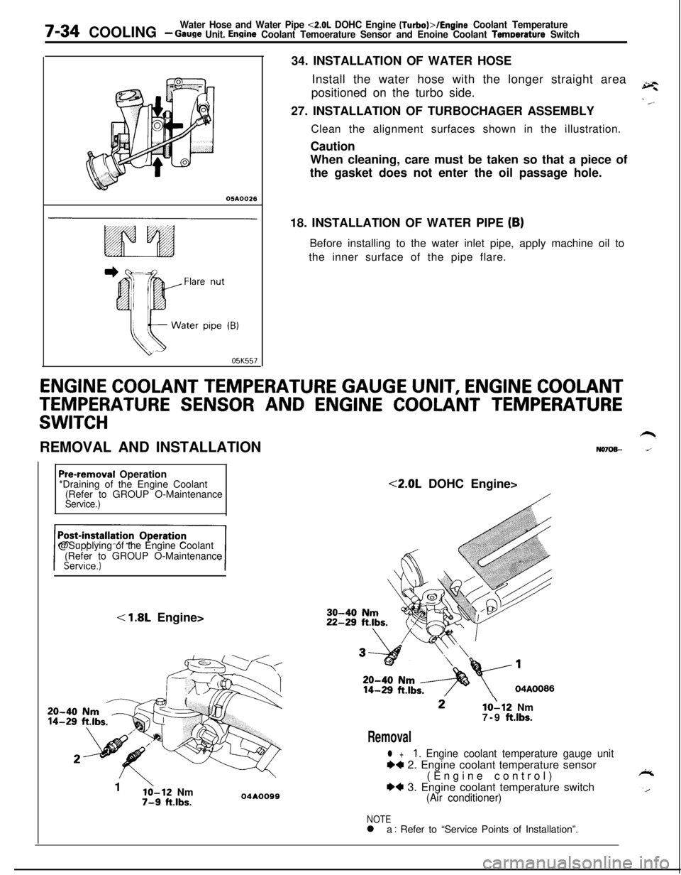
ENGINE COOLANT TEMPERATURE GAUGE UNIT, ENGINE COOLANT
TEMPERATURE SENSOR AND ENGINE COOLANT TEMPERATURE
SWITCHREMOVAL AND INSTALLATION
N070%-
Pre-removal Operation
*Draining of the Engine Coolant
(Refer to GROUP O-Maintenance
Service.)@Supplying of the Engine Coolant
(Refer to GROUP O-Maintenance
< 1.8L Engine>
20-4014-291
’lo-12 Nm7-9 ft.lbs.04AOO99<2.0L DOHC Engine>10112 Nm
7-9 ft.lbs.
Removal
l +1. Engine coolant temperature gauge unit
++ 2. Engine coolant temperature sensor
(Engine control)
*4 3. Engine coolant temperature switch(Air conditioner)
NOTEl a : Refer to “Service Points of Installation”.
Page 315 of 1216

ENGINE <1.8L Engine> - Engine Assembly9-31
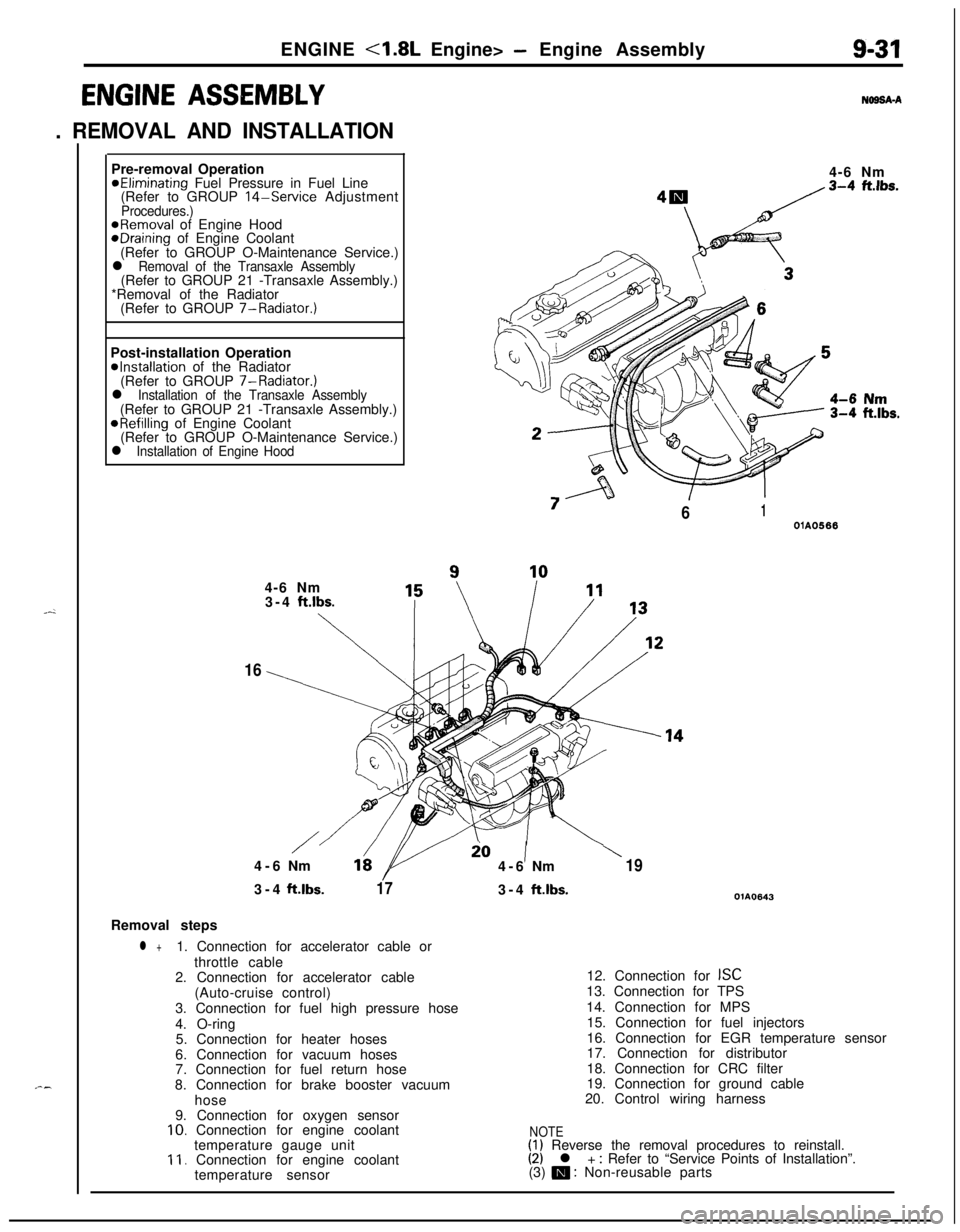
ENGINE ASSEMBLY
. REMOVAL AND INSTALLATION
N69SA-APre-removal Operation
@Eliminating Fuel Pressure in Fuel Line
(Refer to GROUP 14-Service AdjustmentProcedures.)@Removal of Engine HoodeDraining of Engine Coolant
(Refer to GROUP O-Maintenance Service.)
l Removal of the Transaxle Assembly(Refer to GROUP 21 -Transaxle Assembly.)
*Removal of the Radiator
(Refer to GROUP 7-Radiator.)
Post-installation Operation
@Installation of the Radiator
(Refer to GROUP 7-Radiator.)
l Installation of the Transaxle Assembly(Refer to GROUP 21 -Transaxle Assembly.)
@Refilling of Engine Coolant
(Refer to GROUP O-Maintenance Service.)
l Installation of Engine Hood4-6 Nm
“7
/61OlA05664-6 Nm
3-4
ft.lbs.
\
16
/io1\4-6Nm164-6Nm193-4ft.lbs.
173-4ft.lbs.OlA0643Removal steps
l +1. Connection for accelerator cable or
throttle cable
2. Connection for accelerator cable
(Auto-cruise control)
3. Connection for fuel high pressure hose
4. O-ring
5. Connection for heater hoses
6. Connection for vacuum hoses
7. Connection for fuel return hose
8. Connection for brake booster vacuum
hose
9. Connection for oxygen sensor
10. Connection for engine coolant
temperature gauge unit
11. Connection for engine coolant
temperature sensor12. Connection for
ISC13. Connection for TPS
14. Connection for MPS
15. Connection for fuel injectors
16. Connection for EGR temperature sensor
17. Connection for distributor
18. Connection for CRC filter
19. Connection for ground cable
20. Control wiring harness
NOTE(1) Reverse the removal procedures to reinstall.(2) l + : Refer to “Service Points of Installation”.
(3) m : Non-reusable parts
Page 318 of 1216

-
c/
(Refer to GROUP O-Maintenance
9-34ENGINE <1.8L Engine>- Oil Pan and Oil Screen
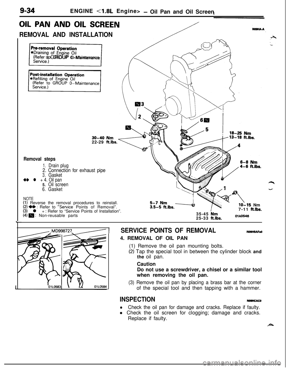
OIL PAN AND OIL SCREEN
REMOVAL AND INSTALLATION
30-40 Nm22-29 ftlbs.
Removal steps
1.Drain plug
2. Connection for exhaust pipe
3.Gasket
** l + 4. Oil pan5.Oil screen
6.Gasket
NOTE(1) Reverse the removal procedures to reinstall.(2) +e : Refer to “Service Points of Removal”.(3) l + : Refer to “Service Points of Installation”.(4) m : Non-reusable parts
lo-15 Nm
7-11 ftlbs.35-45 Nm25-33 ftlbs.OlAO546
,,Mq998727_/ 1SERVICE POINTS OF REMOVALNOSHBAFaO4. REMOVAL OF OIL PAN
(1) Remove the oil pan mounting bolts.
(2) Tap the special tool in between the cylinder block and
the oil pan.
Caution
Do not use a screwdriver, a chisel or a similar tool
when removing the oil pan.
(3) Remove the oil pan by placing a brass bar at the cornerof the special tool and then tapping with a hammer.
INSPECTIONNOHCACO
lCheck the oil pan for damage and cracks. Replace if faulty.l Check the oil screen for clogging; damage and cracks.
Replace if faulty.
Page 371 of 1216

ENGINE <2.0L DOHC Engine> -Camshafts and Camshaft Oil Seals/Oil Pan and Oil Screen9-87
7. INSTALLATION OF ROCKER COVERApply a coating of the specified sealant where shown in
the figure, and then install the rocker cover to the cylinder
head assembly.
Apply sealant
mmin.)
Specified sealant: MOPAR Part No.4318034
or equivalent
olmO47
2. INSTALLATION AND ADJUSTMENT OF TIMING BELTRefer to
P.9-104.
1. ADJUSTMENT OF ACCELERATOR CABLERefer to GROUP 14-Service adjustment procedures.
OIL PAN AND OIL SCREENNO9HA-BREMOVAL AND INSTALLATION
/
/j<&(Refer to GROUP O-Maintenance
\ I/“!18
III13
12-
Removal steps
1.Drain plug2.Self locking nut15-22Nm3.Centermember11-16ft.lbs.7. Connection for exhaust pipe
8.Gasket
9. Connection for oil return pipe (Turbo:IO. Gasket (Turbo)
l * l * 11.Oil pan12.Oil screen
13.Gasket
50-65 Nm*36-47 ft.lbs.*
/117‘1
35-45 NmI25-33 ft.ll3s.
NOTE(I) Reverse the removal procedures to reinstall.(2) l e : Refer to “Service Points of Removal”.
(3) l + : Refer to “Service Points of Installation”.
(4) m : Non-reusable parts
(5)For tightening locations indicated by the * symbol, firsttighten temporarily, and then make the final trghtenrngwith the entire weight of the engine applied to the
vehicle body.
Page 372 of 1216
9-88ENGINE <2.0L DOHC Engine> - Oil Pan and Oil Screen
/
40-60 Nm
30-40 Nm22-29 ft.lbs..
/80-100 Nm458-72
ft.lbs.
70-80 Nm-51-58 ftlbs.15-22 vNm11-16 ft
11b1
Removal steps
1.Drain plug4.Left member
l *5. Transfer assembly6.Drive shaft
7. Exhaust pipe connection
8.Gasket9. Oil return pipe connection
10.Gasket***+ll. Oilpan
12.Oil screen13.Gasket
35-4; Nm25-33 ftlbs.
OlAO620
NOTE(I) Reverse the removal procedures to reinstall.(2) +I) : Refer to “Service Points of Removal”.
(3) H : Refer to “Service Points of Installation”.(4) m : Non-reusable parts
SERVICE POINTS OF REMOVAL
NOBHBAFal
5. REMOVAL OF TRANSFER ASSEMBLYRefer to GROUP 21-Transfer.
11. REMOVAL OF OIL PAN
(1) Remove the oil pan mounting bolts.
(2) Tap the special tool in between the cylinder block and
the oil pan.
Caution
Do not use a screwdriver, a chisel or a similar tool
when removing the oil pan.
(3) Remove the oil pan by placing a brass bar at the correctof the special tool and then tapping with a hammer.
Page 392 of 1216
9-l 08ENGINE <2.0L DOHC Engine> - Timing Belt
.hread diameter
\: 6 x 16(24 x .63)OlAOO45I: 6 x 18 (.24x .70)‘. 6 x 25 (.24 x .98);. 6x28 (.24~1.10) mm (in,)13. INSTALLATION OF TIMING BELT LOWER COVER/
12. TIMING BELT UPPER COVER
F-sThe dimensions of the installation bolts for the timing
covers differ according to the installation location, so be
sure not to install the bolts in the incorrect locations.
8. TENSION ADJUSTMENT OF THE AIR CONDITIONER
COMPRESSOR DRIVE BELT
Refer to GROUP
24-Service Adjustment Procedures.
6. DEFLECTION ADJUSTMENT OF POWER
STEERING OIL .++PUMP DRIVE BELT
Refer to GROUP 1
g-Service Adjustment Procedures.
5.TENSION ADJUSTMENT OF THE ALTERNATOR DRIVE
BELTRefer to GROUP
7-Maintenance Service.