Page 435 of 1216
INTAKE AND EXHAUST - Intake Manifold < 1.8L Engine>
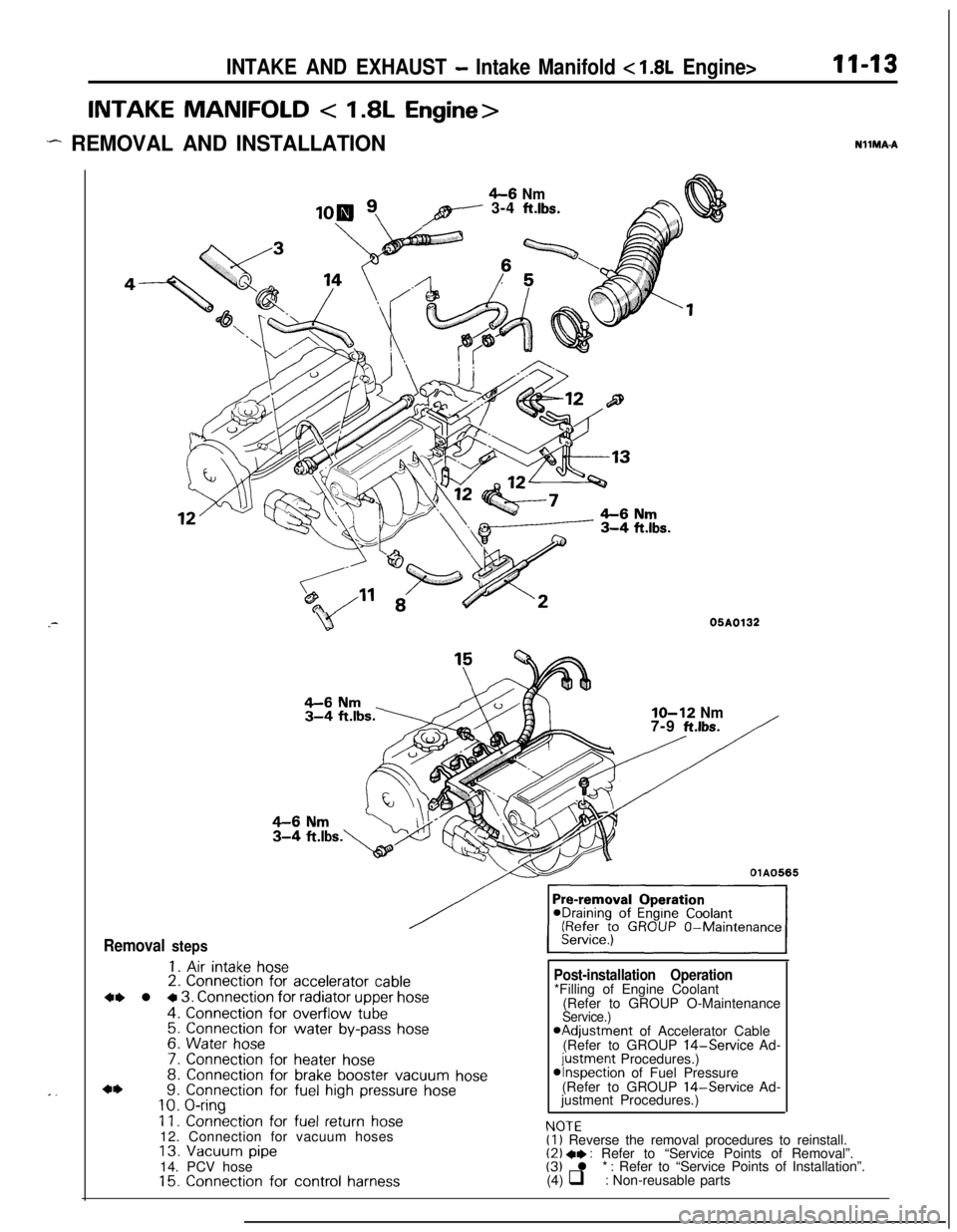
INTAKE MANIFOLD < 1.8L Engine>
.- REMOVAL AND INSTALLATION
11-13NllMA-A.-
. .
4-6 Nmpy---- 3-4 ft.lbs.
B05A0132
Removal steps
1. Air intake hose2. Connection for accelerator cable
4, l + 3. Connection for radiator upper hose
4. Connection for overflow tube5. Connection for water by-pass hose6. Water hose
7. Connection for heater hose8. Connection for brake booster vacuum hose9. Connection for fuel high pressure hose10. O-ring
11. Connection for fuel return hose12. Connection for vacuum hoses
13. Vacuum pipe14. PCV hose
15. Connection for control harness
IO-12 Nm7-9 ft.lbs.
OlA0565
Post-installation Operation
NfJTF*Filling of Engine Coolant
(Refer to GROUP O-Maintenance
Service.)aAdjustment of Accelerator Cable
(Refer to GROUP 14-Service Ad-
justment Procedures.)*Inspection of Fuel Pressure
(Refer to GROUP 14-Service Ad-
justment Procedures.)
I.” IL(1) Reverse the removal procedures to reinstall.(2) +* : Refer to “Service Points of Removal”.(3) l * : Refer to “Service Points of Installation”.
(4) q : Non-reusable parts
Page 439 of 1216
INTAKE AND EXHAUST - Intake Manifold <2.0L DOHC Engine>I I-1.7INTAKE MANIFOLD
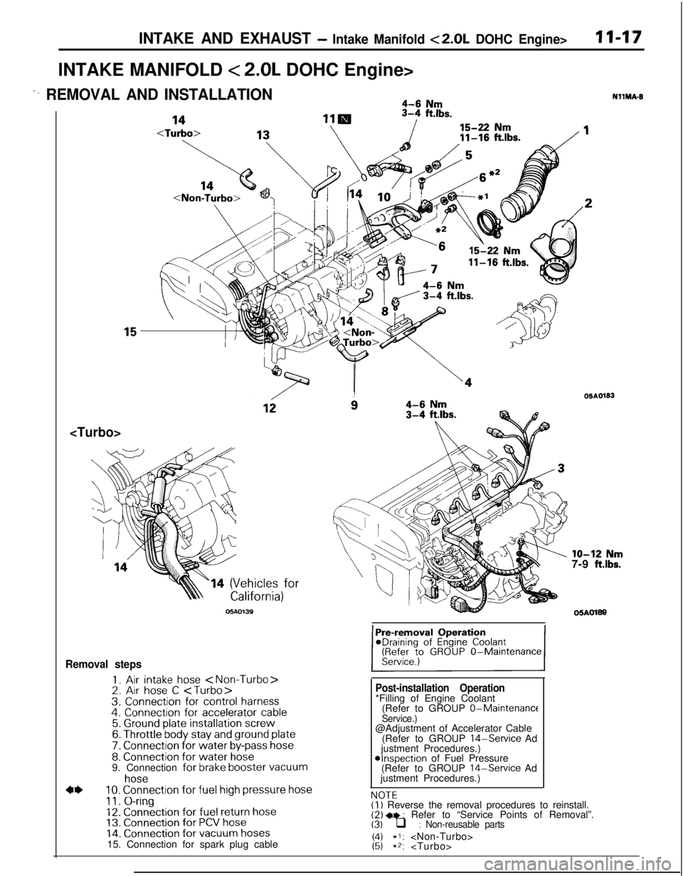
< 2.0L DOHC Engine>
^- REMOVAL AND INSTALLATION4-6 Nm
11-16
ft.lbs.
14 (Vehicles for
05AO139
i34-6 Nm3-4 ftlbs.
Removal steps
I. Air intake hose 2. Air hose C 3. Connection for control harness4. Connection for accelerator cable5. Ground plate installation screw6. Throttle body stay and ground plate
7. Connection for water by-pass hose8. Connection for water hose9. Connection for brake booster vacuum
4*
hose10. Connection for fuel high pressure hose
11. O-ring12. Connection for fuel return hose13. Connection for PCV hose14. Connection for vacuum hoses15. Connection for spark plug cable
Post-installation Operation*Filling of Engine Coolant
(Refer to GROUP 0-Maintenance
Service.)@Adjustment of Accelerator Cable
(Refer to GROUP
14-Service Ad
justment Procedures.)
@Inspection of Fuel Pressure
(Refer to GROUP 14-Service Ad
justment Procedures.)
NOTFNllMA-B
OSAO133
lo-12 Nm7-9 ft.lbs.
05AOl89
,.-.-(I) Reverse the removal procedures to reinstall.(2) +e : Refer to “Service Points of Removal”.(3) q : Non-reusable parts
1:;*I: **:
Page 442 of 1216
II-20INTAKE AND EXHAUST - Turbocharger
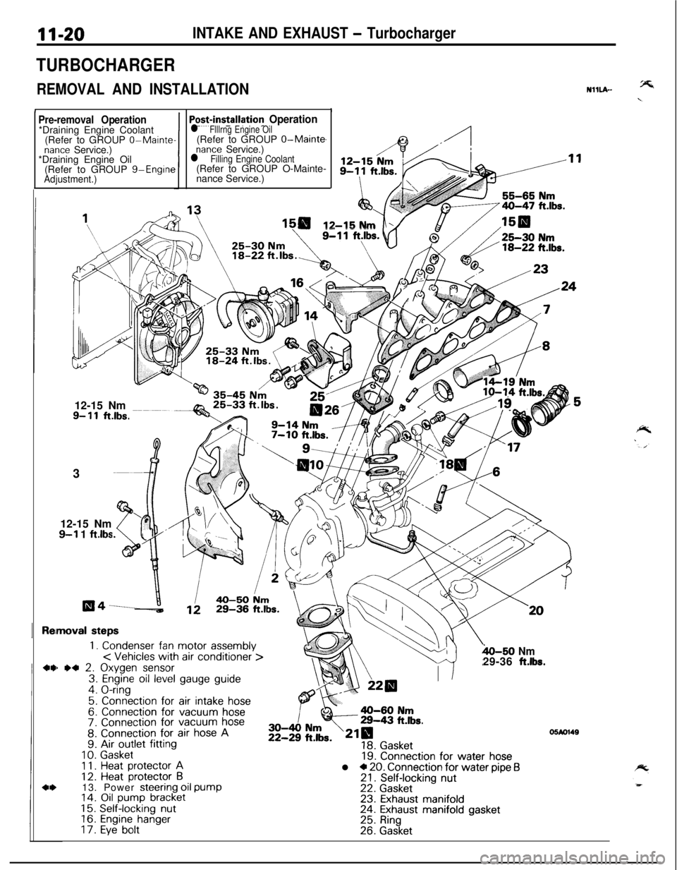
TURBOCHARGER
REMOVAL AND INSTALLATION
II
NHLA-
Pre-removal Operation*Draining Engine Coolant
(Refer to GROUP
0-Maintenance Service.)
*Draining Engine Oil
(Refer to GROUP g-Engine
Adjustment.)1
Po+installation Operationl Flllrng Engine Oil(Refer to GROUP O-Main@
nance Service.)l Filling Engine Coolant(Refer to GROUP O-Mainte-
nance Service.)
12-15 Nm12-15 Nm
9- 11ft.lbs.3
12-15 Nm
9-l 1 ftlbs
moval steps
1. Condenser fan motor assembly< Vehicles with air conditioner >) *4 2. Oxygen sensor3. Engine oil level gauge guide4. O-ring
5. Connection for air intake hose6. Connection for vacuum hose7. Connection for vacuum hose8. Connection for air hose A9. Air outlet fitting
10.Gasket1 1.Heat protector A12. Heat protector B13. Power steering oil pump14. Oil pump bracket15.Self-locking nut16.Engine hanger17.Eye bolt
h-50 Nm29-36 ft.lbs.
19. Connection for water hosel * 20. Connection for water pipe f321. Self-locking nut22. Gasket23. Exhaust manifold24. Exhaust manifold gasket25. Ring26. Gasket
05M1149
Page 707 of 1216

MANUAL TRANSAXLE - Service Adjustment Procedures21-13
II
\
;‘:,
\;
\
\I00”011009FOli
I
I09K56i
09K56f
,
SERVICE ADJUSTMENT PROCEDURESN21FBABlTRANSAXLE OIL LEVEL INSPECTION
Refer to GROUP O-Maintenance Service.
TRANSAXLE OIL REPLACEMENT
NZlFCADa(1) Position vehicle on a flat level.
(2) Remove filler and drain plugs and allow the transaxle oil to
drain.(3) Refill the transaxle to the proper level with specified
transaxle oil. The oil level should be the bottom of the oil
filler hole.
Transaxle oil: MOPAR Hypoid gear oil or equivalent
API classification
GL-4 or hiqher
1.8 liters (1.9 qts.)
2.2 liters ‘(2.3 qts.)DRIVE SHAFT OIL SEALS REPLACEMENT
NZlFDACa
(1) Disconnect the drive shaft from the transaxle.
(Refer to GROUP
2-Drive Shaft.)
(2) Using a flat-tip
(-) screwdriver, remove the oil seal.
(3) Using the special tool, tap the drive shaft oil seal into the
transaxle.
(4) Apply a coating of the transaxle oil to the lip of the oil seal.Transaxle oil: MOPAR Hypoid gear oil or equivalent
API classification
GL-4 or higher
Page 773 of 1216
MANUAL TRANSAXLE - Troubleshooting/Service Adjustment Proceduresm-79
--/OQA0024
09FOll
TROUBLESHOOTINGRefer to
P.21-12.NIlEAAE
SERVICE ADJUSTMENT
PROCED’URES
TRANSAXLE OIL LEVEL INSPECTIONN2lFBAB1Refer to GROUP O-Maintenance Service.
TRANSAXLE OIL REPLACEMENTN2lFCAH(1) Position vehicle on a flat level and remove filler and drain
plugs to drain transaxle oil.
(2) Pour in fresh transaxle oil through filler port until it reaches
the bottom of filler port.
Transaxle oil: MOPAR Hypoid gear oil or equivalent,
API classification
GL-4 or higher.
Transaxle: 2.3 liters (2.4
qts.)Transfer: 0.6 liter
(.6 qt.)
Page 869 of 1216
AUTOMATIC TRANSAXLE - TroubleshootingBased upon use of the troubleshooting
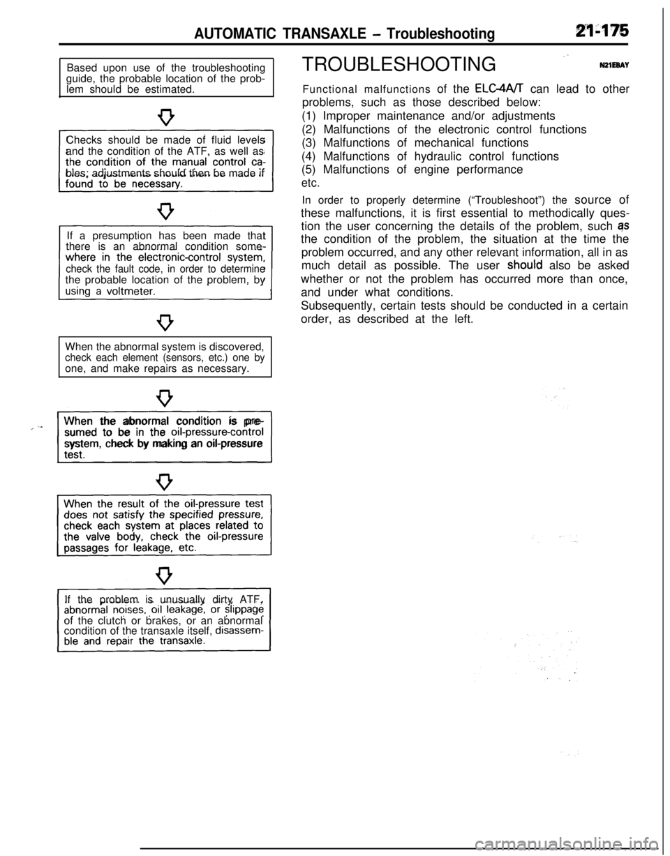
guide, the probable location of the prob-
lem should be estimated.
Checks should be made of fluid levels
and the condition of the ATF, as well as
bles; adjustments should then be made if
If a presumption has been made that
there is an abnormal condition some-
check the fault code, in order to determinethe probable location of the problem, by
When the abnormal system is discovered,
check each element (sensors, etc.) one byone, and make repairs as necessary.
“~^II_When the abnormal condition is pre-
sumed to be in the
orI-pressure-controlsystem, check by making an oil-pressure
If the problem is unusually dirty ATF,
of the clutch or brakes, or an abnormal
condition of the transaxle itself,
disassem-TROUBLESHOOTING
”N21EeAYFunctional malfunctions of the ELC4A/T can lead to other
problems, such as those described below:
(1) Improper maintenance and/or adjustments
(2) Malfunctions of the electronic control functions
(3) Malfunctions of mechanical functions
(4) Malfunctions of hydraulic control functions
(5) Malfunctions of engine performance
etc.In order to properly determine (“Troubleshoot”) the source of
these malfunctions, it is first essential to methodically ques-
tion the user concerning the details of the problem, such qs
the condition of the problem, the situation at the time the
problem occurred, and any other relevant information, all in as
much detail as possible. The user
shoutd also be asked
whether or not the problem has occurred more than once,
and under what conditions.
Subsequently, certain tests should be conducted in a certain
order, as described at the left.
Page 903 of 1216

AUTOMATIC TRANSAXLE - service Adjustment Procedures21-209
09Pooi awith this range.
09POOll
TWO382
SERVICE ADJUSTMENT PROCEDURESN21FB6E
TRANSAXLE FLUID LEVEL INSPECTION1. Drive until the fluid temperature reaches the usual tem-
perature
[70-80°C (160- 18O”F)I.2. Place vehicle on level floor.
3. Move selector lever sequentially to every position to fill
torque converter and hydraulic circuit with fluid, then place
lever in “N” Neutral position.
4. Before removing dipstick, wipe all dirt from area around
dipstick. Then take out the dipstick and check the conditionof the fluid.
The transaxle should be overhauled under the following
conditions.l If there is a “burning” odor.
l If the fluid color has become noticeably blacker.
lIf there is a noticeably great amount of metal particles inthe fluid.
5.Check to see if fluid level is in “HOT” range on dipstick. If
fluid level is low, add automatic transaxle fluid until level
reaches “HOT” range.
Transaxle fluid: MOPAR ATF PLUS (Automatic trans-
mission fluid type 7176) or Dia ATF SPor equivalent
Low fluid level can cause a variety of conditions
becaljse it
allows pump to take in air along with fluid. Air trapped in
hydraulic circuit forms bubbles which make fluid spongy.
Therefore, pressures will be erratic, causing delayed shift,
slippy clutch and brakes, etc.
Improper filling can also raise fluid level too high. When
transaxle has too much fluid, gears churn up foam and
cause the same conditions which occur with low fluid level,
resulting in accelerated deterioration of automatic transaxle
fluid.In either case, air bubbles can cause overheating, fluid
oxidation, which can interfere with normal valve, clutch,
and servo operation.Foaming can also result in fluid
escaping from transaxle vent where it may be mistaken for
a leak.6. Be sure to examine fluid on dipstick closely.
TRANSAXLE FLUID REPLACEMENTN21FCBAaRefer to GROUP O-Maintenance Service.
TRANSFER OIL LEVEL INSPECTIONNZlFXAATransfer oil level inspection is the same as for the manual
transaxle transfer.
Refer to GROUP
22-Service Adjustment Procedures.
TRANSFER OIL REPLACEMENTNZlFYAFaTransfer oil replacement is the same as for manual transaxle
transfer.Refer to GROUP
22-Service Adjustment Procedures.
Page 918 of 1216
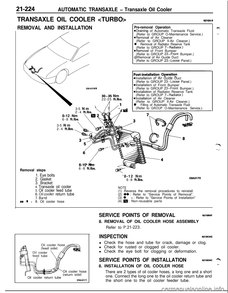
21-224AUTOMATIC TRANSAXLE - Transaxle Oil Cooler
TRANSAXLE OIL COOLER
REMOVAL AND INSTALLATION
OQA01691
30-35 Nm
22-25 ft.lbs.
/I1’
Removal steps
1. Eye bolts
2. Gasket3-5 Nm
‘\/I/ --
2-4
ftlbs.8-12 Nm
m26-8 ft.lbs.\\
N21SA-B
Pre-removal OperationeDraining of Automatic Transaxle Fluid
(Refer to GROUP O-Maintenance Service.)
@Removal of Air Cleaner
(Refer to GROUP II-Air Cleaner.)
l Removal of Radiator Reserve Tank(Refer to GROUP 7-Radiator.)
@Removal of Front Bumper
(Refer to GROUP 23-Front Bumper.)
@Removal of Air Guide Duct
(Refer to GROUP
23-Loose Panel.)
*Installation of Air Guide Duct
(Refer to GROUP 23-Loose Panel.)*Installation of Front Bumper
(Refer to GROUP 23-Front Bumper.)@Installation of Radiator Reserve Tank
(Refer to GROUP 7-Radiator.)
*Installation of Air Cleaner
(Refer to GROUP II-Air Cleaner.)
l Filling of Automatic Transaxle Fluid(Refer toGROUPO-MaintenanceService.)3-5 Nm
2-4
ftlbs.8-12 Nm
6-8
ft.lbs.‘8-12 Nm
6-8
ftlbs.OBAOl703. Bracket
4. Transaxle oil cooler5. Oil cooler feed tubeNOTE(1) Reverse the removal procedures to reinstall.
7: ~i&~oler return tube(2) ++ : Refer to “Service Points of Removal”.
(3) l + : Refer to “Service Points of Installation”
+e l +8. Oil cooler hose(4) m : Non-reusable parts
Oil cooler hose
Oilcoolerreturn tube09A0171
&.
-=-.
SERVICE POINTS OF REMOVALNZlSBAF8. REMOVAL OF OIL COOLER HOSE ASSEMBLY
Refer to
P.21-223.
INSPECTIONN2lSCAGl Check the hose and tube for crack, damage or clog.
l Check for rusted or clogged oil cooler.
l Check the eye bolt for clogging or deformation.
SERVICE POINTS OF INSTALLATIONN2lSDAC ‘-+8. INSTALLATION OF OIL COOLER HOSE_
There are 2 types of oil cooler hoses, a long one and a shortone. Connect the long one to the oil cooler return tube and
the short one to the oil cooler feeder tube.