Page 1147 of 1216

HEATERS AND AIR CONDITIONING - Specifications/Troubleshooting24-3LUBRICANTS
u24as-
;xiItemsSpecified lubricantsQuantity
Each connection of refrigerant lineDENS0 OIL 6 or
SUNISO 5GSAs required
Shaft seal of the compressor
SEALANT AND ADHESIVES, Items
Engine coolant temperature switch threaded partSpecified sealant and adhesive
MOPAR Part No.4318034 or equivalentN24CE-
TROUBLESHOOTINGN24EBAQ
SymptomHeater insufficient heat
No ventilation even when
mode selection knob is
operatedBlower motor inoperative
Probable causeObstructed heater outlets
Blend air dampers improperly adjusted or bindingThermostat malfunction
Obstructed heater hoses
Improperly adjusted control cables
Plugged or partially plugged heater core
Incorrect adjustment of mode selection dampersIncorrect installation of mode selection control wire
Ducts are incorrectly/incompletely connected, crushed,
bent or clogged.
Poor grounding
Burnt-out fuseMalfunction blower switch
Malfunction resister
Malfunction blower motor
Malfunction heater relay
Remedy
Correct
ReplaceAdjust
Clean or replaceAdjust
Repair or replace
Correct
Replace
Page 1148 of 1216

24-4HEATERS AND AIR CONDITIONING - Troubleshooting
TROUBLESHOOTING QUICK-REFERENCE TABLE
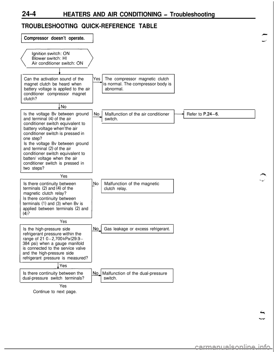
Compressor doesn’t operate.Air conditioner switch: ON
1
Can the activation sound of theYesThe compressor magnetic clutch
magnet clutch be heard when
- is normal. The compressor body is
battery voltage is applied to the airabnormal.
conditioner compressor magnet
clutch?
Is the voltage Bv between ground
and terminal
(4) of the airconditioner switch equivalent to
battery voltage when’the air
conditioner switch is pressed in
one step?
Is the voltage Bv between ground
and terminal
(2) of the airconditioner switch equivalent to
batten/ voltage when the air
conditioner switch is pressed in
two steps?
YesIs there continuity between
terminals (2) and (4) of the
magnetic clutch relay?
Is there continuity between
terminals (1) and (3) when Bv is
applied between terminals
(2) and
(4)?
L
i
I
Yes
Is the high-pressure siderefrigerant pressure within the
range of 21 O-2,700 kPa (29.9-
384 psi) when a gauge manifold
is connected to the service valve
and the high-pressure side
refrigerant pressure is measured?
/YesMalfunction of the air conditioner
switch.
Refer to P.24-6.
r
1!
\loMalfunction of the magnetic
clutch relay.
Gas leakage or excess refrigerant.Is there continuity between the
dual-pressure switch terminals?
No_ Malfunction of the dual-pressure
switch.
Yes
Continue to next page.
Page 1149 of 1216
HEATERS AND AIR CONDITIONING - Troubleshooting24-5
From previoys page.
When the resistance of the air-
therm0 sensor is measured[with the air conditioner switch
OFF and when the ambient
temperature of the
air-therm0sensor is
25°C (77“F)], is the
measured resistance approx.
1.5f0.15 kP?
INoMalfunction of tha air-therm0Refer to P.24-6.-sensor.
Refer to P.24-6.
1Yes
When the resistance of the air-
inlet sensor is measured [with the
air conditioner switch OFF andwhen the ambient temperature of
the air-inlet sensor is 25°C (77”F)l
is the measured resistanceapprox.
1.5f0.15 k&2?I
1 Yes
Does idle-up occur immediatelyNo Malfunction of the DC motor
after the air conditioner switch is
cl800 Engine>
switched ON?Malfunction of the stepper motor
Yes~2000 DOHC Engine>
Malfunction of the MPI control unit
* Malfunction of the air conditioner
control unit.Refer to P.24-6.
Page 1150 of 1216

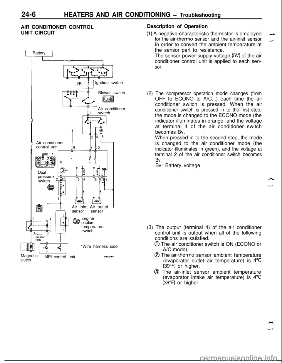
24-6HEATERS AND AIR CONDITIONING - TroubleshootingAIR CONDITIONER CONTROL
UNIT CIRCUIT
1 Battery IBlower switch
litalAir conditioner
IAir inlet Air outlet1-isensorsensor
temperature
Corn- L Tpressor
relayI IMagnetic
AclutchMPI control*Wire harness sideDescription of Operation
(1) A negative-characteristic thermistor is employed
for the air-therm0 sensor and the air-inlet sensorin order to convert the ambient temperature at
the sensor part to resistance.
The sensor power-supply voltage
(5V) of the air
conditioner control unit is applied to each sen-
sor.
(2) The compressor operation mode changes (fromOFF to ECONO to A/C...) each time the air
conditioner switch is pressed. When the air
conditioner switch is pressed in to the first step,the mode is changed to the ECONO mode (the
indicator illuminates in orange, and the voltage
at terminal 4 of the air conditioner switch
becomes Bv.
When pressed in to the second step, the mode
is changed to the air conditioner mode (the
indicator illuminates in green), and the voltage at
terminal 2 of the air conditioner switch becomes
Bv.Bv: Battery voltage
(3) The output (terminal 4) of the air conditioner
control unit is output when all of the following
conditions are satisfied.
@ The air conditioner switch is ON (ECONO or
A/C mode).
@ The air-therm0 sensor ambient temperature
(evaporator outlet air temperature) is
4°C
(39°F) or higher.
@ The air-inlet sensor ambient temperature
(evaporator intake air temperature) is
4°C
(39°F) or higher.
Page 1151 of 1216
HEATERS AND AIR CONDITIONING - Troubleshootinq
-.
’ Wire harness sideTROUBLESHOOTING HINTS
Inspection of Air Conditioner Control Unit
Disconnect the amplifier and inspect the connector on the wireharness side as shown in the chart below.
Test Conditions:
(1) Ignition switch: ON
(2) Air conditioner switch: ON
(3) Temoerature control lever: MAX COOL2OAO405
(4j Bloier switch: HI
TerminalMeasurement item
Tester connectionConditions
Specified value
1Resistancel-6-1,500f150 sz ’at 25°C (77°F)
2
10
Voltage2-3
2-8Airtcchonditioner
ContinuityContinuity3-Ground
4-Ground
Resistance5-7
-ContinuityII
8-Ground-
Voltage9-3
9-8Therm0 sensor OFF78°C (172°F)
:5k (185°F)
Voltage10-3ECONO switch
10-8
System voltageov
Continuity
Continuity1,500+
150 s-2at 25°C (77’F)
Continuity
System voltageov
System? voltageov
If the connector on the wire harness side is correct, replace the air conditioner control unit.
Page 1152 of 1216
24-8HEATERS AND AIR CONDITIONING - Troubleshooting
IARNESSES AND COMPONENTS LAYOUT DIAGRAM
1. Air conditioner switch
2. Air conditioner control unit
3. Air-inlet sensor
4.
Air-therm0 sensor
36AOO51
NameSymbolAir conditioner control unit
DAir conditioner switch
GAir inlet sensor
FAir
therm0 sensorFBlower motor High relay
E
IrrIor:enser fan motor High-Low selecting
C
NameCondenser fan motor relay
Dual pressure switch
Engine coolant temperature switch
<2.0L DOHC Engine>
Heater relay
Magnetic clutch relay
Symbol
C
BA
H
C
NOTEThe “Name” column is arranged in alphabetical order.
q \
q ---
Page 1153 of 1216
HEATERS AND AIR CONDITIONING - Troubleshooting24-9Blower motor High relay
Page 1154 of 1216

24-10HEATERS AND AIR CONDITIONING - Safety Precautions
SAFETY PRECAUTIONSN24PAAD
The refrigerant used in all air conditioner is R-l 2. It istransparent and colorless in both the liquid and
vapor state. Since it has a boiling point of
-29.8”C(-85.6”F).
at atmospheric pressure, it will be a vapor
at all normal temperatures and pressures. The vaporis heavier than air, non-flammable, and nonexplo-
sive. It is nonpoisonous except when it is in direct
contact with open flame. It
ia noncorrosive except
when combined with water. The following precau-
tions must be observed when handling
R-12.Caution
Wear safety goggles when servicing the refriger-ation system.
R-12 evaporates so rapidly at normal atmospheric
pressures and temperatures that it tends to freeze
anything it contacts. For this reason, extreme care
must be taken to prevent any liquid refrigerant from
contacting the skin and especially the eyes. Always
wear safety goggles when servicing the refrigera-
tion part of the air conditioning system. Keep a
bottle of sterile mineral oil handy when working on
the refrigeration system. Should any liquid re-
frigerant get into the eyes, use a few drops of
mineral oil to wash them out.
R-12 is rapidly
absorbed by the oil. Next splash the eyes with
plenty of cold water. Call your doctor immediately
even though irritation has ceased after treatment.
Caution
Do not heat
R-12 above 40°C (104°F).In most instances, moderate heat is required to
bring the pressure of the refrigerant in its container
above the pressure of the system when charging or
adding refrigerant. A bucket or large pan of hot
water not over
40°C (104°F) is all the heat required
for this purpose. Do not heat the refrigerant contain-
er with a blow torch or any other means that would
raise temperature and pressure above this tempera-ture. Do not weld or steam clean on or near the
system components or refrigerant lines.
Caution
Keep
R-12 containers upright when charging the
system.When metering
R-12 into the refrigeration system,
keep the supply tank or cans in an upright position. Ifthe refrigerant container is on its side or upside
down, liquid refrigerant will enter the system and
damage the compressor.Caution
Always work in a well-ventilated room.
‘irrGood ventilation is vital in the working area. Always
discharge the refrigerant into the service bay ex-
haust system or outside the building. Large quanti-
ties of refrigerant vapor in a small, poorly ventilated
room can displace the air and cause suffocation.
Although
R-12 vapor is normally nonpoisonous,
contact with an open flame can cause the vapor to
become very poisonous. Do not discharge large
quantities of refrigerant in an area having an open
flame. A poisonous gas is produced when using theflame-type leak detector. Avoid inhaling the fumes
from the leak detector.
Caution
Do not allow liquid refrigerant to touch bright
metal.
Refrigerant will tarnish bright metal and chrome
surfaces, and in combination with moisture can
severely corrode all metal surfaces.
R-12 Refrigerant Bundling
Refrigerant Recycling
R-12 refrigerant is a chloro-floro-carbon (CFC) that
can contribute to the depletion of the ozone layer in
the upper atmosphere.A
Ozone filters out harmful radiation from the sun.
- -/.To assist in protecting the ozone layer, Mitsubishi
Motors Corporation
recomends that a R-12 re-
frigerant recycling device that meets SAE standard
J1991 be used.
Contact an automotive service equipment supplier
for refrigerant recycling equipment that is available
in your area.
Refer to the operating instructions provided with therecycling equipment for proper operation.