1991 MITSUBISHI ECLIPSE coolant temperature
[x] Cancel search: coolant temperaturePage 358 of 1216

9-74ENGINE <2.0L DOHC Engine>- Service Adjustment Procedures
ENGINE <2.0L DOHC Engine>
SERVICE ADJUSTMENT PROCEDURES pi
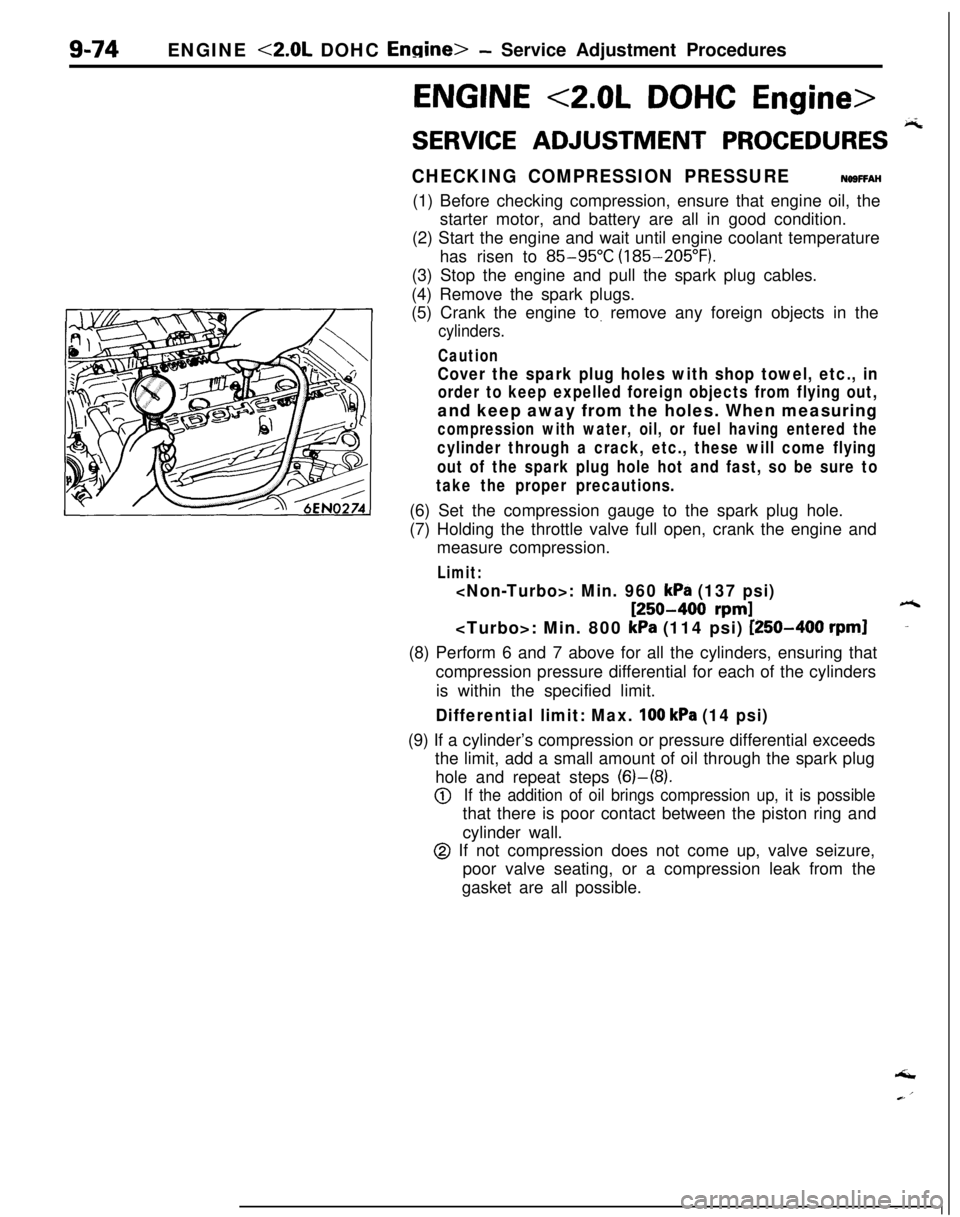
CHECKING COMPRESSION PRESSURENOSFFAH(1) Before checking compression, ensure that engine oil, the
starter motor, and battery are all in good condition.
(2) Start the engine and wait until engine coolant temperature
has risen to
85-95°C (185-205°F).
(3) Stop the engine and pull the spark plug cables.
(4) Remove the spark plugs.
(5) Crank the engine
to. remove any foreign objects in the
cylinders.
Caution
Cover the spark plug holes with shop towel, etc., in
order to keep expelled foreign objects from flying out,and keep away from the holes. When measuring
compression with water, oil, or fuel having entered the
cylinder through a crack, etc., these will come flying
out of the spark plug hole hot and fast, so be sure to
take the proper precautions.(6) Set the compression gauge to the spark plug hole.
(7) Holding the throttle valve full open, crank the engine and
measure compression.
Limit:
[250-400 rpm]6
kPa (114 psi) [250-400 rpml-(8) Perform 6 and 7 above for all the cylinders, ensuring that
compression pressure differential for each of the cylinders
is within the specified limit.
Differential limit: Max. 100 kPa (14 psi)(9) If a cylinder’s compression or pressure differential exceeds
the limit, add a small amount of oil through the spark plug
hole and repeat steps (6)-(8).
@If the addition of oil brings compression up, it is possiblethat there is poor contact between the piston ring and
cylinder wall.
@ If not compression does not come up, valve seizure,
poor valve seating, or a compression leak from the
gasket are all possible.‘I
Page 359 of 1216

_-
a--ENGINE
<2.0L DOHC Engine> -Service Adjustment Procedures9-75
JMANIFOLD VACUUM INSPECTION
NO9FNAO(1) Before inspection and adjustment, put the vehicle into the
following state.
l Engine coolant temperature:
85-g5”C (185-205°F)
l Lights, electric, cooling fan, and accessories: OFF
lTransaxle: Neutral (N or
P for vehicles with an automa-
tic transaxle)
l Steering wheel: Neutral position
(2) Check that the idling revolution speed is normal.
(3) Remove the PCV hose from the PCV valve and attach a
vacuum gauge.
(4) Check that the negative pressure at the intake manifold
during idle revolution is normal.
Standard value:
mmHg (19.3 in.Hg)
mmHg (18.9 in.Hg)(5) If outside the standard value, isolate the cause by referring
to the following table and repair the fault.
ymptomICause1 Remedy
The vacuum gauge reading is less than
standard value, but the pointer is
stable.
The vacuum gauge pointer swingsslowly.
l Ignition timing is retarded.
l Air mixture concentration too
rich.
l Adjust the ignition timing.
l Check ECI-MULTI system.
The vacuum gauge pointer drops
irre-gularly.l Air mixture concentration too
lean.
l Check ECI-MULTI system.
The vacuum gauge pointer drops inter-mittently to 30 to 160
mmHg (1.2 to
6.3 in.Hg).
The vacuum gauge pointer drops sud-
denly from the normal reading to 250
mmHg (9.8 in.Hg), then returns tonormal.
l Incomplete close contact of in-
take and exhaust valve seat.
l Broken cylinder head gasket
l Check and repair the valve.
l Replace cylinder head gasket.
Page 365 of 1216

ENGINE <2.0L DOHC Engine> - Engine Assembly
ENGINE ASSEMBLY
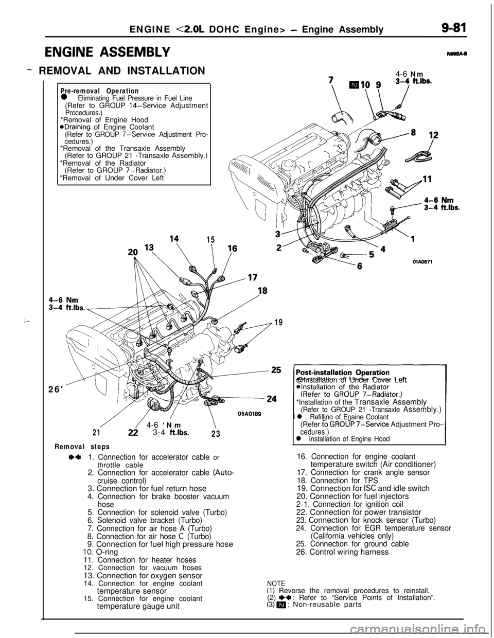
- REMOVAL AND INSTALLATION
;-
Pre-removal Operationl Eliminating Fuel Pressure in Fuel Line(Refer to GROUP 14-Service AdjustmentProcedures.)*Removal of Engine Hood
@Draining of Engine Coolant(Refer to GROUP 7-Service Adjustment Pro-
cedures.)*Removal of the Transaxle Assembly
(Refer to GROUP 21 -Transaxle Assembly.)
*Removal of the Radiator
(Refer to GROUP 7-Radiator.)
*Removal of Under Cover Left
26'
15
I4-6 Nm\I /MAO571
19@Installation of Under Cover Left
*Installation of the Transaxle Assembly
(Refer to GROUP 21 -Transaxle Assembly.)
I l Refilling of Enaine Coolant
/22/ 4-6 ‘Nm\213-4 ftlbs.23
Removal steps
~~1. Connection for accelerator cable orthrottle cable
2. Connection for accelerator cable (Auto-
cruise control)3. Connection for fuel return hose
4. Connection for brake booster vacuum
hose
5. Connection for solenoid valve (Turbo)
6. Solenoid valve bracket (Turbo)
7. Connection for air hose A (Turbo)
8. Connection for air hose
C (Turbo)9. Connection for fuel high pressure hose
10. O-ring11. Connection for heater hoses12. Connection for vacuum hoses
13. Connection for oxygen sensor
14. Connection for engine coolant
temperature sensor
15. Connection for engine coolant
temperature gauge unit(Refer
t’o GROUP 7-Service Adjustment Pro-cedures.)l Installation of Engine Hood‘I
16. Connection for engine coolanttemperature switch (Air conditioner)
17. Connection for crank angle sensor
18. Connection for TPS19. Connection for
ISC and idle switch
20. Connection for fuel injectors
2 1. Connection for ignition coil22. Connection for power transistor
23. Connection for knock sensor (Turbo)
24. Connection for EGR temperature sensor
(California vehicles only)
25. Connection for ground cable26. Control wiring harness
NOTE(I) Reverse the removal procedures to reinstall.
(2) e+ : Refer to “Service Points of Installation”.(3) m : Non-reusable parts
Page 374 of 1216

9-90ENGINE <2.0L DOHC Engine> - Cylinder Head Gasket
CYLINDER HEAD GASKETNOSJA-S2.5-3.5 Nm 19
3 4 K
REIVIOVAL AND INSTALLATION2-3 ft.lbs.\ I i-6
Pre-removal Operation*Eliminating Fuel Pressure in Fuel20Line1\(Refer to GROUP 14-Service Ad-justment Procedures.)eDraining of Engine Coolant(Refer to GROUP 7-Service Adjust-
ment Procedures.)
,,vs4-6 Nm
’
II28
2936’
/w,=
3i38OlAO5.69
Removal stepsl
1. Connection for accelerator cable orthrottle cable
2. Connection for accelerator cable (Auto-
cruise control)3. Connection for oxygen sensor
temperature sensor
5. Connection for engine coolant
temperature gauge unit6. Connection for engine coolant
7. Connection for crank angle sensor
8. Connection for TPS
ISC and idle switch
10. Connection for fuel injector
12. Connection for power transistor
13. Connection for knock sensor (Turbo)
14. Connection for EGR temperature sensor
(California vehicles only)
15. Connection for ground cable
+e l + 17. Connection for radiator upper hose
/\05ADl9019. Center cover
20. Connection for spark plug cable assembly
21. Connection for air intake hose (Turbo)
22. Connection for breather hose (Turbo)
23.Airintakehose24. Connection for breather hose+e l 25. Connection for fuel high pressure hose26. O-ring
27. Connection for vacuum hoses
28. Connection for heater hose
29. Connection for water by-pass hose
30. Connection for PCV hose
31. Connection for vacuum hose (Turbo)
32. Connection for water hose (Turbo)
33. Eye-bolt (Turbo)
34. Gasket (Turbo)
35. Connection for oil pipe (Turbo)
36. Connection for vacuum hoses (Turbo)
37. Connection for fuel return hose
38. Connection for brake booster vacuum
hoseA
NOTE(1) Reverse the removal procedures to reinstall.(2) +I) : Refer to “Service Points of Removal”.
(3) ~~ : Refer to “Service Points of Installation”.
(4) m : Non-reusable parts
Page 455 of 1216

14-IFUEL SYSTEM
CONTENTS
AUTO-CRUISECONTROLSYSTEM...........................................109AUTO-CRUISECONTROL.......................................................140SERVICEADJUSTMENTPROCEDURES..............................135Accelerator Cable, Throttle Cable and Auto-cruise
ControlCableInspectionandAdjustment........................136Auto-cruise
ControlSystemInspection.............................135lndrvrdualPartsInspection..................................................137SPECIFICATIONS.....................................................................109GeneralSpecifications.......................................................109ServiceSpecifications
.........................................................109Torque Specrfications..........................................................109TROUBLESHOOTING...............................................................110Auto-CruiseControlCircurt................................................128Auto-cruise
ControlComponentsLocation........................126Auto-cruise Control Related Harnesses
.............................125Check Chart
........................................................................114Input Check.........................................................................123Self-diagnosis
Check..........................................................121Troubleshootrng
Quick-referenceChart..............................110ENGINECONTROL.......................................................................105ENGINECONTROL..................................................................107--SERVICEADJUSTMENTPROCEDURES..............................106Accelerator Cable Inspection and Adjustment..................106Accelerator Switch Inspectron and Adjustment................106SPECIFICATIONS.....................................................................105Lubricants.............................................................................105Sealant.................................................................................105ServiceSpecifications
..........................................................105TorqueSpecifications..........................................................105TROUBLESHOOTING...............................................................105FUELSYSTEM..............................................................................2FUELFILTER............................................................................104FUELLINEANDVAPORLINE..............................................102FUEL PUMP, FUEL GAUGE UNIT ANDOVERFILL LIMITER(TWO-WAY VALVE)
Switch........................................................64Air Conditioner Power Relay
..............................................67Components
Location......................................................56
ControlRelay
.................................................................66EGRControlSolenoidValve...............................................67EGRTemperatureSensor..................................................64Engine Coolant Temperature Sensor
.................................62IdlePosrtionSwitch
...........................................................63IdleSpeedControlServo
.............................
....................65InhibitorSwitch....................................................................65hjeCtOrS................................................................................65IntakeAirTemperatureSensor..........................................6’2MalfunctionlndtcatorLight
..........................................58MotorPosition
Sensor................................................63OxygenSensor
.................................................................64Power Steering 011 Pressure Swatch...........................65PowerTransistor
................................................................67PurgeControlSolenoidValve.........................................67
Self-Diagnosis.......................................................................
ThrottlePositronSensor.....................................................
Vehicle Speed Sensor.........................................................MPI
SYSTEMINSPECTION<2.0L DOHCEngine>...........Air Conditioner Power Relay..............................................
Arr Conditioner Swatch........................................................
Components Location
.........................................................
Control
Relay.......................................................................
EGR Control Solenoid Valve...............................................
EGR Temperature Sensor
...................................................
Engine Coolant Temperature Sensor
.................................Fuel Pressure Control Valve...............................................
Idle Position Switch
............................................................
Idle
SpeedControlServo...................................................Injectors
................................................................................
Intake Air Temperature Sensor..........................................
Malfunction Indicator Light.................................................
Oxygen Sensor
....................................................................
Power
Steering
OilPressureSwitch.................................Power Transistor
.................................................................
Purge Control Solenoid Valve.............................................
Self-Diaanosis.......................................................................
58
63
2382
79
688182
79
7682
77
79
79
76
727879
82
8273ThrottletiPosition Sensor
.....................................................77Vehicle Speed Sensor
.........................................................79SERVICE ADJUSTMENT PROCEDURES<1.8L Engine>........................................................................41Curb Idle Speed Inspection
................................................41EGR Valve Control Vacuum Check....................................47Fuel Pressure Test
..............................................................44Fuel Pump Operation Check
..............................................44Idle Speed Control and Throttle Position
Sensor Adjustment
..............................................................
41Purge Port Vacuum Check
.................................................47Release of Residual Pressure from
High Pressure Fuel Hose
...................................................
44Throttle
Body(Throttle Valve Area)Cleaning....................43SERVICE ADJUSTMENT PROCEDURES<2.0LDOHCEngine>............................................................48Basic Idle Speed Adjustment
.............................................
48
Curb Idle Speed Inspection
................................................48EGR Valve Control Vacuum Check....................................55Fuel Pressure Test
..............................................................52Fuel Pump Operation Check
..............................................51Idle Position Switch Adjustment........................................52Purge Port Vacuum Check
.................................................55Release of Residual Pressure from
High Pressure Fuel Hose
...................................................51Throttle Body (Throttle Valve Area) Cleaning....................51ThrottlePositionSensorAdjustment.................................50SPECIALTOOLS......................................................................6SPECIFICATIONS.....................................................................2GeneralSpecifications.........................................................2Sealant and Adhesive
.........................................................5Service Specifications
..........................................................4Torque Specifications
..........................................................5THROlTLEBODY<1.8LEngine>........................................85THROlTLE BODY <2.0L DOHC Engine>............................89TROUBLESHOOTING...............................................................6
Page 456 of 1216

14-2FUEL SYSTEM - Specifications
FUEL SYSTEM
SPECIFICATIONS
GENERAL SPECIFICATIONSNW%-
4.8L Engine>
Items
Fuel
Tank capacity
Return system
Filter
Fuel pump
Type
Driven by
Throttle bodyThrottle
bore
Throttle position sensor
Idle speed control servo
Idle position switchMotor position
sensor
Engine control unitIdentification
model No.
For Federal and Canada
For California
SensorsAir flow
sensor
Barometric pressure sensor
Intake air temperature sensor
Engine coolant temperature sensorOxygen
sensor
Vehicle speed sensorInhibitor switch
No. 1 cylinder top dead center sensor
Crank angle sensor
EGR temperature sensor
Control relay type
Injector type and number
Injector identification mark
Purge control solenoid valve
EGR control solenoid valve
Fuel pressure regulator
Regulated pressure
Specificationsliter
(gal.) 60 (15.9)
Equipped
High pressure type
Electrical, in-tank type
Electric motor
mm (in.) 50 (1.97)
Variable resistor type
Electric motor
Contact type, within idle speed control servo
Variable resistor type
E2T33674
E2T33673
Karman vortex type
Semiconductor diffusion typeThermistor typeThermistor type
Zirconia type
Reed switch type
Contact switch type
Photo interrupter type
Photo interrupter typeThermistor type
Contact switch type
Electromagnetic, 4
N210H
ON/OFF type solenoid valveDuty
cycle type solenoid valve
kPa (psi) 335 (47.6)
Page 457 of 1216

FUEL SYSTEM - Specifications14-3
<2.0L DOHC Engine>
ItemsSpecifications
Fuel
Tank capacityliter (gal.) 60 (15.9)
Return systemEquipped
FilterHigh pressure type
Fuel pump
TypeElectrical, in-tank type
Driven byElectric motor
Throttle bodyThrottle
boremm (in.) 60 (2.36)Throttle position
sensorVariable resistor type
Idle speed control servoStepper motor type
The stepper motor type by- ass air controlsystem with the Fast Idle6!rr Valve (FIAV)
Idle position switchContact switch type
Engine control unitIdentification
model No.
For Federal
E2T36574
E2T36576
E2T36578
E2T36582
For California
E2T36573
E2T36575
E2T36577
E2T36581
SensorsAir flow
sensorKarman vortex type
Barometric pressure sensorSemiconductor diffusion-type
Intake air temperature sensorThermistor type
Engine coolant temperature sensorThermistor type
Oxygen sensorZirconia type
Vehicle-speed sensorReed switch typeDetonation
sensor
Top dead center sensorPhoto interrupter type
Crank angle sensorPhoto interrupter type
EGR temperature sensor
Power steering oil pressure switchContact switch type4ctuators
Control relayContact switch type
Resistor identification model No.E8T05873
Injector type and numberElectromagnetic, 4
Injector identification mark
B450L
B390L
Purge control solenoid valveON/OFF type solenoid valve
EGR control solenoid valve
Fuel pressure control solenoid valve
gate solenoid valve
Page 458 of 1216

FUEL SYSTEM- Specifications
ItemsSpecifications
Fuel pressure regulator
Regulated pressurekPa (psi)
255 (36.3)
SERVICE SPECIFICATIONS
<1.8L Engine>N14CB-
ItemsSpecifications
Basic ignition timing~
Curb idle speedvm
, Idle speed when air conditioner is onrpm
Basic idle speedwm
Throttle position sensor adjusting voltageV
Throttle position sensor resistancekQMotor position
sensor resistancek&
Idle speed control servo motor coil resistance
Intake air temperature sensor resistancekQ
Engine coolant temperature sensor resistance
20°C (68°F)
80°C (176°F)
Fuel pressurekPa (psi)
Vacuum hose disconnection
Vacuum hose connection
Iniectnr coil resistance Q
52
k8
5”BTDC at curb idle
700f 100
850 at neutral position
650 at D range
700 f 50
0.48-0.52 at curb idle
3.5-6.5
4-6
5-35 [at 20°C (68”F)l
2.7 [at 20°C (68”F)I
2.5
0.3
330-350 (47-50) at curb idleApprox.
270 (38) at curb idle
13-16 [at 20°C (68”F)l
<2.0L DOHC Engine>
Items( Specifications
Basic ignition timing
Curb idle speedrpm
Idle speed when air conditioner is onrpm
al-r>
Basic idle speedrpm
Throttle position sensor adjustment voltageVThrottle position
sensor resistancekQ
Idle speed control servo (stepper motor) coil resistance
Intake air temperature sensor resistancekQ
Engine coolant temperature sensor resistancek0
20°C (68°F)
80°C (176°F)
Fuel pressurekPa (psi)
Vacuum hose disconnection
Vacuum hose connection
Q
5”+ 2”BTDC at curb idle
750+ 100
850 at neutral position
650 at D range
750 f 50
0.48-0.52 at curb idle
3.5-6.5
28-33 [at 20°C (68”F)l
2.7 [at 20°C (68”F)I
2.5
0.3
330-350 (47-50) at curb idle
250-270 (36-38) at curb idle
290-320 (41-46) at curb idleApprox.
270 (38) at curb idle
Approx. 190 (27) at curb idle
Approx. 230 (33) at curb idle