1991 MITSUBISHI ECLIPSE battery
[x] Cancel search: batteryPage 179 of 1216
![MITSUBISHI ECLIPSE 1991 Service Manual BRAKES - Anti-lock Braking System Troubleshooting5-39
E-6Abnormality of valve relay drive circuitI
j-a [Explanation]When the ignition switch is turned ON, the ABSnormal. In addition, normally it monit MITSUBISHI ECLIPSE 1991 Service Manual BRAKES - Anti-lock Braking System Troubleshooting5-39
E-6Abnormality of valve relay drive circuitI
j-a [Explanation]When the ignition switch is turned ON, the ABSnormal. In addition, normally it monit](/manual-img/19/57104/w960_57104-178.png)
BRAKES - Anti-lock Braking System Troubleshooting5-39
E-6Abnormality of valve relay drive circuitI
j-a [Explanation]When the ignition switch is turned ON, the ABSnormal. In addition, normally it monitors whether or
ECU switches the valve relay OFF and ON for annot there is power in the valve power monitor line
initial check, compares the voltage of the signal tosince the valve relay is normally ON. Then, if the
the valve relay and valve power monitor line voltagesupply of power to the valve power monitor line is
to check whether the valve relay operation is
interrupted, the warning light illuminates.
IGNITIONMAIN FUSIBLESWITCHLINK @W-31)When the valve relay is
checked, are the followingconditions found?No.85-No.86:resistancevalue 60-120 Q
No.30-No.87a: continuityNo.30-No.87: No continui-
When battery voltage is ap-plied between terminals
No.86 and No. 85 grounded.
No. 30-No. 87: continuity
No.
30-No. 87a: no continui-
tyremove the HU connec-
NoValve relay malfunction
Replace valve relay.
IConnect the HU
remove the ECU con-
I Yes
IValve relay drive circuit isnormal.I
Page 180 of 1216
![MITSUBISHI ECLIPSE 1991 Service Manual 5-40BRAKES - Anti-lock Braking System Troubleshooting
E-7Abnormality of motor drive circuit
[Explanation]The ABS ECU illuminates the warning light for the
motor relay and motor in the following cases. MITSUBISHI ECLIPSE 1991 Service Manual 5-40BRAKES - Anti-lock Braking System Troubleshooting
E-7Abnormality of motor drive circuit
[Explanation]The ABS ECU illuminates the warning light for the
motor relay and motor in the following cases.](/manual-img/19/57104/w960_57104-179.png)
5-40BRAKES - Anti-lock Braking System Troubleshooting
E-7Abnormality of motor drive circuit
[Explanation]The ABS ECU illuminates the warning light for the
motor relay and motor in the following cases.
l When the motor relay does not function
lWhen there is trouble with the motor itself and it
does not revolve
[Hint]If there is motor operation noise when wheel speed
exceeds
Gkm/h (4mph) when starting up after the
engine is started, there is a broken or short circuitedmotor monitor wire.
lWhen the motor ground line is disconnected andthe motor does not revolve
l When the motor continues to revolve
Does the motor make a
YesBroken wire or short cir-noise when wheel speed
-cuit in motor monitor line
exceeds 6 km/h (4 mph)?
b
NoRepair the harness between HU and ECU.
emove the motor rela
ABS ECU
14A0105
Remove the motor relav and
check resistance values.
No.
85-No. 86:resistancevalue 30-60 QNo.30-No.87: no continui-
ty
Battery voltage is applied on
terminals No. 86 and No. 85
grounded
No. 30-No. 87: continuity
Yes
q Motor relay malfunction 1
Replace motor relay.I
Is pump motor ground con-netted normally?Connect ground wire.I
b
Does voltage between bodyNo
connector terminal 51 andIBroken wire in pumpmotor power circuit
ground indicate battery vol-
tage?1Repair the harness.
YesIs resistance between body
- No L Malfunction of harness
connector terminal No. 2 andbetween HU and ECU
No.26 30-60 ohms?b
YesRepair harness.
Motor drive circuit is normal.
Page 192 of 1216
5-52BRAKES - Service Adjustment Procedures
16LO312lOWOO
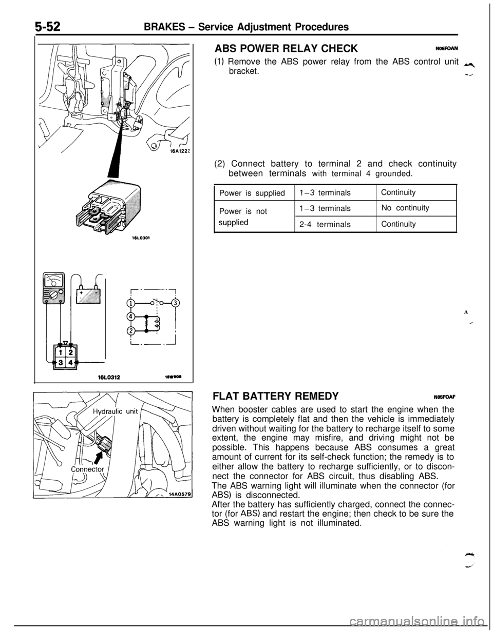
(1) Remove the ABS power relay from the ABS control unit q
bracket.-/ABS POWER RELAY CHECK
NO5FOAN(2) Connect battery to terminal 2 and check continuity
between terminals with terminal 4 grounded.
Power is supplied
Power is not
supplied
l-3 terminals
1-3 terminals
2-4 terminalsContinuity
No continuity
Continuity
A
IFLAT BATTERY REMEDYNOWOAF
When booster cables are used to start the engine when the
battery is completely flat and then the vehicle is immediately
driven without waiting for the battery to recharge itself to some
extent, the engine may misfire, and driving might not be
possible. This happens because ABS consumes a great
amount of current for its self-check function; the remedy is to
either allow the battery to recharge sufficiently, or to discon-
nect the connector for ABS circuit, thus disabling ABS.
The ABS warning light will illuminate when the connector (for
ABS) is disconnected.
After the battery has sufficiently charged, connect the connec-
tor (for
ABS) and restart the engine; then check to be sure the
ABS warning light is not illuminated.
Page 262 of 1216
7-14COOLING - Radiator
A
OFF
ON
h
--- ,
BWatertemperature
16v1100
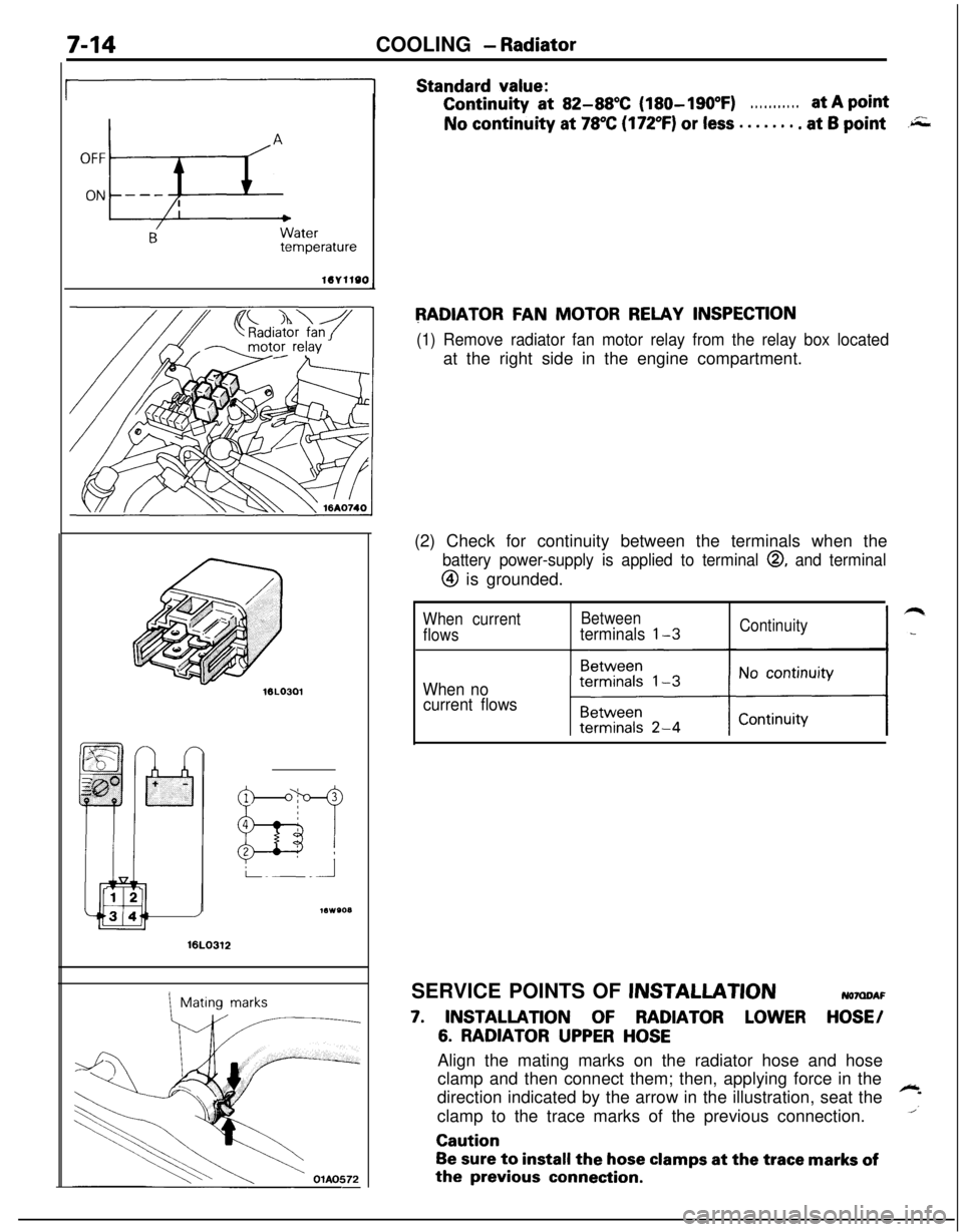
Standard value:Continuity
at 82-88X (180-190°F). . . . . . . . . . .at A pointNo continuity at
78°C (172°F) or less . . . . . . . . at 6 point.r;;;
RADIATOR FAN MOTOR RELAY INSPECTION
(1) Remove radiator fan motor relay from the relay box locatedat the right side in the engine compartment.
16LO312
1Mating marks(2) Check for continuity between the terminals when the
battery power-supply is applied to terminal 0, and terminal
@ is grounded.
When currentBetween
flowsterminals l-3Continuity
When no
current flowsSERVICE POINTS OF
JNSTALLATIONNOMDAF
7. INSTALLATION OF RADIATOR LOWER HOSE/
6. RADIATOR UPPER HOSEAlign the mating marks on the radiator hose and hose
clamp and then connect them; then, applying force in the
direction indicated by the arrow in the illustration, seat the
~
1clamp to the trace marks of the previous connection.Caution
Be sure to install the hose clamps at the trace marks ofthe
previous connection.
Page 308 of 1216
9-24ENGINE - Service Adjustment Procedures
ENGINE 4.8L Engine>
SERVICE ADJUSTMENT PROCEDURES -
CHECKING COMPRESSION PRESSURENOSFFAI
(1) Before checking compression, ensure that engine oil, the
starter motor, and battery are all in good condition.
(2) Start the engine and wait until engine coolant temperature
has risen to
85-95°C (185-205°F).
(3) Stop the engine and pull the spark plug cables.
(4) Remove the spark plugs.
(5) Crank the engine to remove any foreign objects in the
cylinders.Caution
Cover the spark plug holes with shop towel, etc., in
order to keep expelled foreign objects from flying out,
and keep away from the holes. When measuring
compression with water, oil, or fuel having entered the
cylinder through a crack, etc., these will come flying
out of the spark plug hole hot and fast, so be sure to
take the proper precautions.
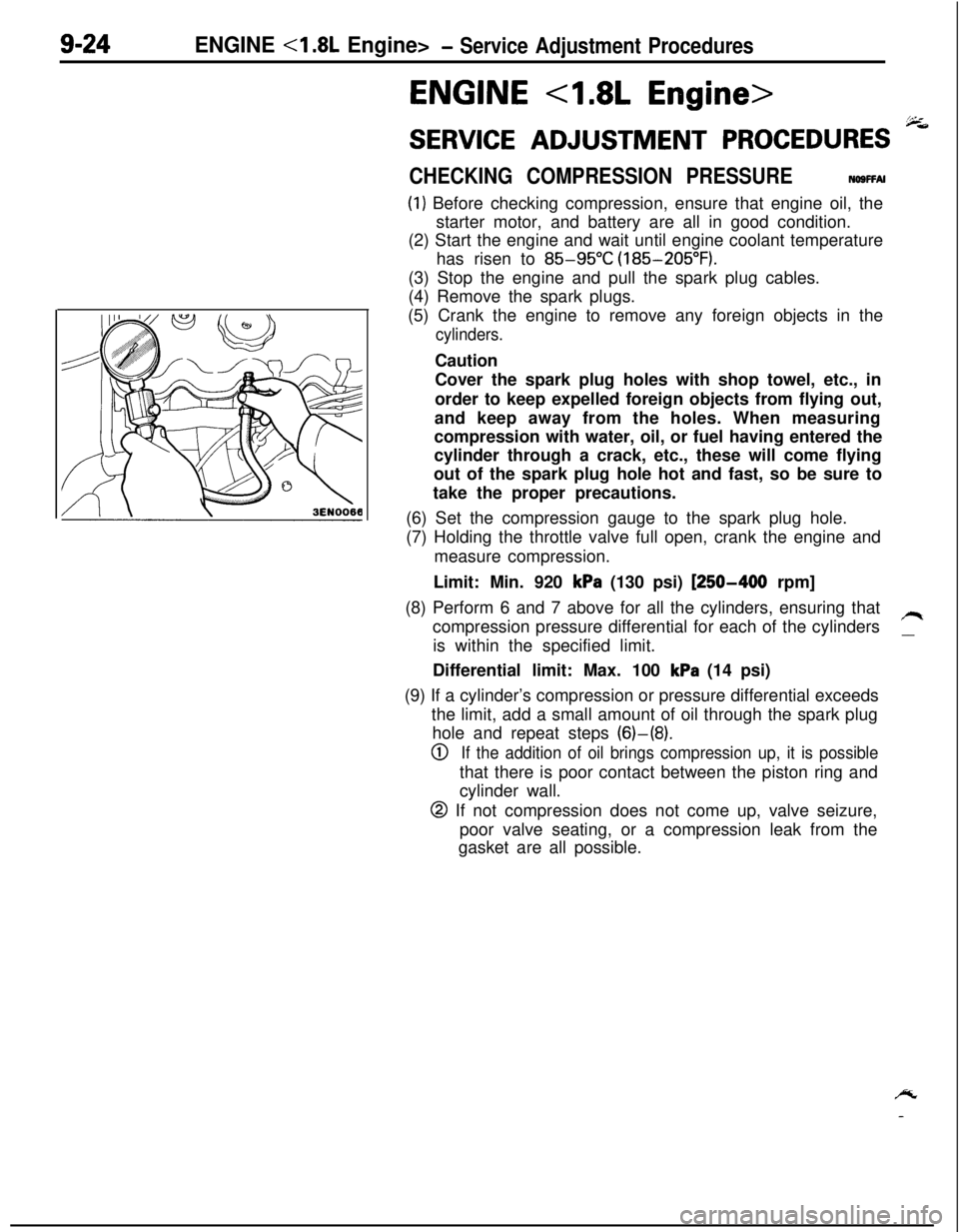
(6) Set the compression gauge to the spark plug hole.
(7) Holding the throttle valve full open, crank the engine and
measure compression.
Limit: Min. 920
kPa (130 psi) [250-400 rpm]
(8) Perform 6 and 7 above for all the cylinders, ensuring that
compression pressure differential for each of the cylinders
/Iis within the specified limit.
__Differential limit: Max. 100
kPa (14 psi)
(9) If a cylinder’s compression or pressure differential exceeds
the limit, add a small amount of oil through the spark plug
hole and repeat steps (6)-(8).
0If the addition of oil brings compression up, it is possiblethat there is poor contact between the piston ring and
cylinder wall.
@ If not compression does not come up, valve seizure,
poor valve seating, or a compression leak from the
gasket are all possible.
/y
-
Page 358 of 1216
9-74ENGINE <2.0L DOHC Engine>- Service Adjustment Procedures
ENGINE <2.0L DOHC Engine>
SERVICE ADJUSTMENT PROCEDURES pi
CHECKING COMPRESSION PRESSURENOSFFAH(1) Before checking compression, ensure that engine oil, the
starter motor, and battery are all in good condition.
(2) Start the engine and wait until engine coolant temperature
has risen to
85-95°C (185-205°F).
(3) Stop the engine and pull the spark plug cables.
(4) Remove the spark plugs.
(5) Crank the engine
to. remove any foreign objects in the
cylinders.
Caution
Cover the spark plug holes with shop towel, etc., in
order to keep expelled foreign objects from flying out,and keep away from the holes. When measuring
compression with water, oil, or fuel having entered the
cylinder through a crack, etc., these will come flying
out of the spark plug hole hot and fast, so be sure to
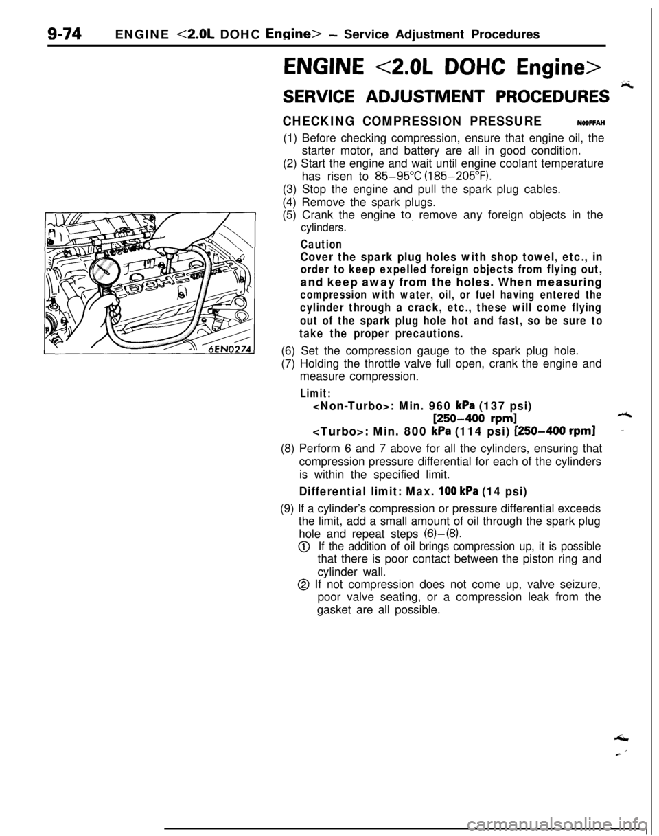
take the proper precautions.(6) Set the compression gauge to the spark plug hole.
(7) Holding the throttle valve full open, crank the engine and
measure compression.
Limit:
[250-400 rpm]6
kPa (114 psi) [250-400 rpml-(8) Perform 6 and 7 above for all the cylinders, ensuring that
compression pressure differential for each of the cylinders
is within the specified limit.
Differential limit: Max. 100 kPa (14 psi)(9) If a cylinder’s compression or pressure differential exceeds
the limit, add a small amount of oil through the spark plug
hole and repeat steps (6)-(8).
@If the addition of oil brings compression up, it is possiblethat there is poor contact between the piston ring and
cylinder wall.
@ If not compression does not come up, valve seizure,
poor valve seating, or a compression leak from the
gasket are all possible.‘I
Page 428 of 1216
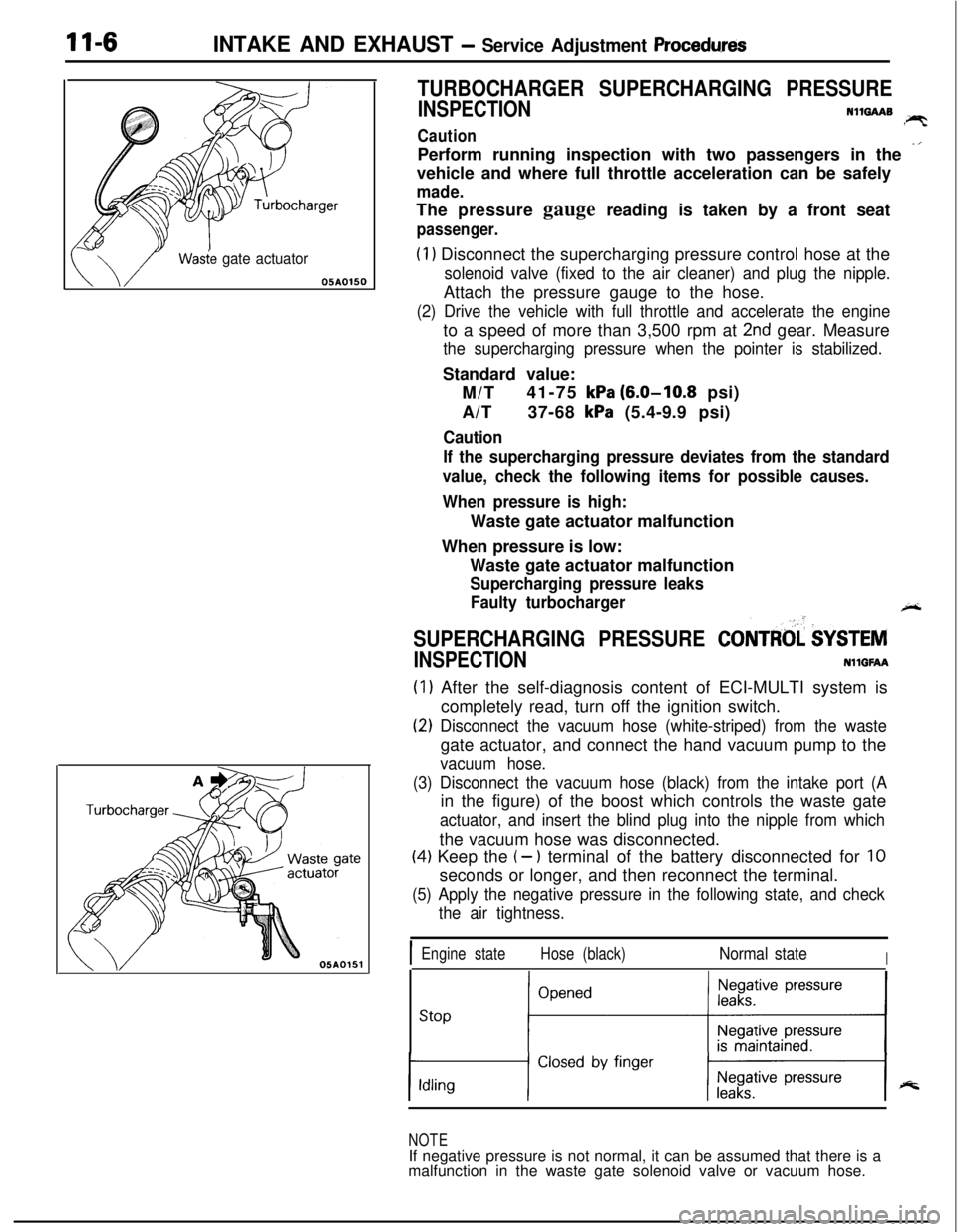
11-6INTAKE AND EXHAUST - Service Adjustment Procedwes
Wasie gate actuator05AOlSO
TURBOCHARGER SUPERCHARGING PRESSURE
INSPECTIONN1mAAB!PTCautionPerform running inspection with two passengers in the
-’vehicle and where full throttle acceleration can be safely
made.The pressure gauge reading is taken by a front seat
passenger.
(1) Disconnect the supercharging pressure control hose at the
solenoid valve (fixed to the air cleaner) and plug the nipple.Attach the pressure gauge to the hose.
(2) Drive the vehicle with full throttle and accelerate the engineto a speed of more than 3,500 rpm at
2nd gear. Measure
the supercharging pressure when the pointer is stabilized.Standard value:
M/T41-75
kPa (6.0-10.8 psi)
A/T37-68
kPa (5.4-9.9 psi)
Caution
If the supercharging pressure deviates from the standard
value, check the following items for possible causes.
When pressure is high:Waste gate actuator malfunction
When pressure is low:
Waste gate actuator malfunction
Supercharging pressure leaks
Faulty turbocharger
+-
SUPERCHARGING PRESSURE CONTRtd $YSTEM
INSPECTIONNllGFAA
(1) After the self-diagnosis content of ECI-MULTI system is
completely read, turn off the ignition switch.
(2) Disconnect the vacuum hose (white-striped) from the wastegate actuator, and connect the hand vacuum pump to the
vacuum hose.
(3) Disconnect the vacuum hose (black) from the intake port (Ain the figure) of the boost which controls the waste gate
actuator, and insert the blind plug into the nipple from whichthe vacuum hose was disconnected.
(4) Keep the (- ) terminal of the battery disconnected for 10seconds or longer, and then reconnect the terminal.
(5) Apply the negative pressure in the following state, and check
the air tightness.
IEngine stateHose (black)Normal stateI
stop ;“““*I
NOTEIf negative pressure is not normal, it can be assumed that there is a
malfunction in the waste gate solenoid valve or vacuum hose.
Page 429 of 1216
INTAKE AND EXHAUST - Service Adjustment ProceduresII-7
w05A0155
h61
NO06061
NO0616 I
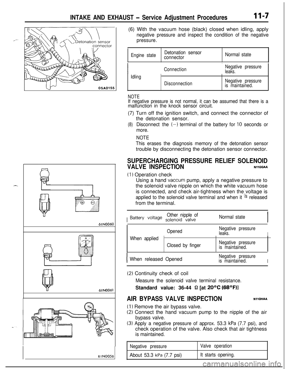
NO056(6) With the vacuum hose (black) closed when idling, apply
negative pressure and inspect the condition of the negative
pressure.
Engine stateDetonation sensor
connectorNormal state
,
ConnectionNegative pressureleaks.
Idling
DisconnectionNegative pressure
is maintained.
NOTEIf negative pressure is not normal, it can be assumed that there is amalfunction in the knock sensor circuit.(7) Turn off the ignition switch, and connect the connector of
the detonation sensor.
(8)Disconnect the (-) terminal of the battery for 10 seconds or
more.
NOTE
This erases the diagnosis memory of the detonation sensortrouble by disconnecting the detonation sensor connector.
SUPERCHARGING PRESSURE RELIEF SOLENOID
VALVE INSPECTIONNllGGAA
(1) Operation check
Using a hand
vaccum pump, apply a negative pressure to
the solenoid valve nipple on which the white vacuum hose
is connected, and check air-tightness when the voltage is
applied to the solenoid valve terminal and when it i‘s releasedfrom the terminal.
I
Other nipple ofBattery voile solenoid valveNormal state
OpenedNegative pressureleaks.IWhen applied
Closed by fingerNegative pressure
is maintained.
IWhen released OpenedNegative pressure
is maintained.
I
(2) Continuity check of coil
Measure the solenoid valve terminal resistance.Standard value: 36-44
fl [at 20°C (68OF)l
AIR BYPASS VALVE INSPECTIONNllGHAA
(1) Remove the air bypass valve.
(2) Connect the hand vacuum pump to the nipple of the air
bypass valve.
(3) Apply a negative pressure of approx. 53.3 kPa (7.7 psi), andcheck operation of the valve. Also check that air tightness
is maintained.
Negative pressure
About 53.3 kPa (7.7 psi)
Valve operation
It starts opening.