Page 1191 of 1216

HEATERS AND AIR CONDITIONING - Refrigerant Line24-47
REFRIGERANT LINE
- -REMOVAL AND INSTALLATIONN24UA-Pre-removal Operation
*Discharge of theRefrigerant
(Refer to
P.24-19.)@Removal of Battery and ReserveTank@Removal of Air-cleaner and Aircleaner Bracket (Refer to GROUF
1 1 -Air-cleaner.)Post-installation Operation
@Installation of Air-cleaner Bracketand Air-cleaner (Refer to GROUP11 -Air-cleaner.)
l installation of Battery and Re-
serve tank
Kharging of Refrigerant
(Refer to P.24-21.)@Checking for Gas(Refer to P.24-15.)Leakage
@Performance Test(Refer to
P.24-16.)9-11 Nm ,
7-8 ft.lbs.
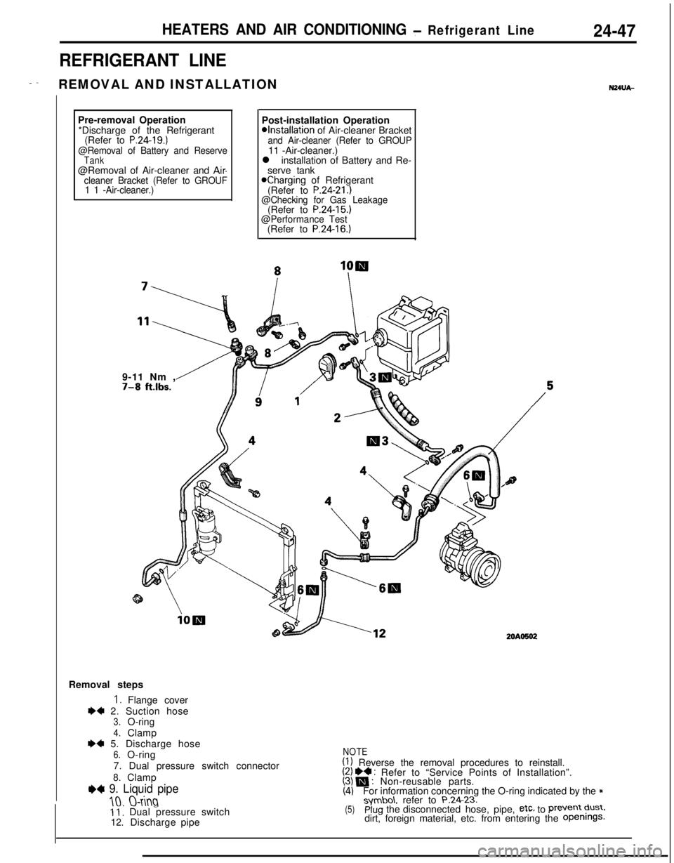
20AO502Removal steps
I. Flange cover
I)+ 2. Suction hose3.O-ring
4.ClampI)* 5. Discharge hose6.O-ring
7. Dual pressure switch connector
8.Clamp
e+ 9. Liquid pipe
10.O-ring11, Dual pressure switch12.Dischargepipe
NOTE(1) Reverse the removal procedures to reinstall.(2) I)4 : Refer to “Service Points of Installation”.(3) N : Non-reusable parts.(4)For information concerning the O-ring indicated by the *symbo\. refer to P.24.23.(5)plug the disconnected hose, pipe, etc, to Prevent dust.dirt, foreign material, etc. from entering the Openings.
Page 1209 of 1216

EMISSION CONTROL SYSTEMS- Evaporative Emission Control System25-WECl51C
PURGE CONTROL VALVE
INSPECTION
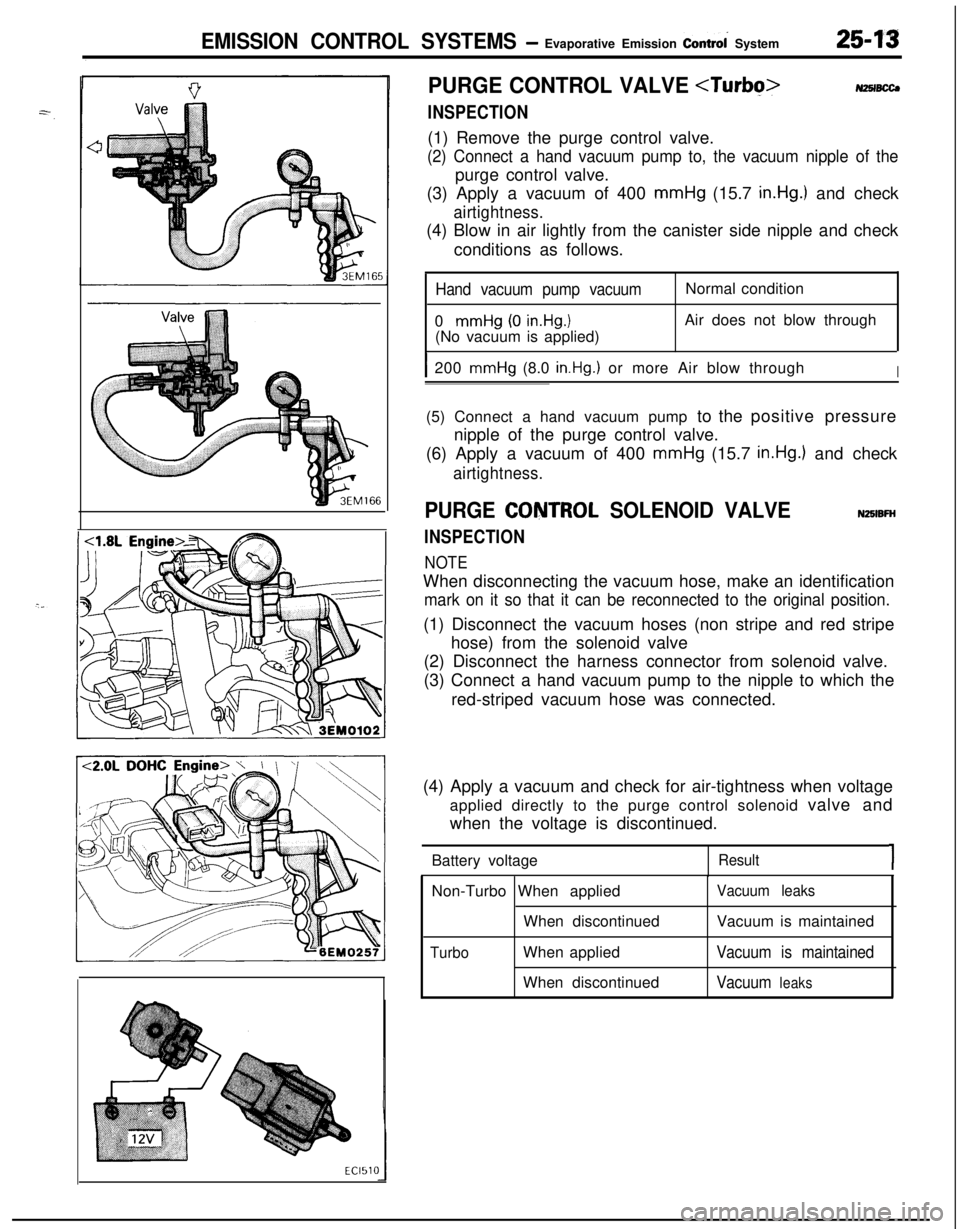
NZSIBCCJ(1) Remove the purge control valve.
(2) Connect a hand vacuum pump to, the vacuum nipple of thepurge control valve.
(3) Apply a vacuum of 400 mmHg (15.7
in.Hg.) and check
airtightness.(4) Blow in air lightly from the canister side nipple and check
conditions as follows.
Hand vacuum pump vacuum0
mmHg (0 in.Hg.1(No vacuum is applied)Normal condition
Air does not blow through
I200 mmHg (8.0 in.Hg.) or more Air blow throughI(5) Connect a hand vacuum pump to the positive pressure
nipple of the purge control valve.
(6) Apply a vacuum of 400 mmHg (15.7
in.Hg.) and check
airtightness.
PURGE CQNTROL SOLENOID VALVE
INSPECTION
NOTE
NZBIBFHWhen disconnecting the vacuum hose, make an identification
mark on it so that it can be reconnected to the original position.(1) Disconnect the vacuum hoses (non stripe and red stripe
hose) from the solenoid valve
(2) Disconnect the harness connector from solenoid valve.
(3) Connect a hand vacuum pump to the nipple to which the
red-striped vacuum hose was connected.
(4) Apply a vacuum and check for air-tightness when voltage
applied directly to the purge control solenoid valve and
when the voltage is discontinued.
Battery voltage
Result1Non-Turbo When applied
When discontinued
TurboWhen applied
When discontinued
Vacuum leaksVacuum is maintained
Vacuum is maintained
Vacuum
leaks
Page 1215 of 1216

EMISSION CONTROL SYSTEMS- Exhaust Gas Recirculation (EGR) Svstem25-19
\\
7EM0043
. .
6EM0187
EGR TEMPERATURE SENSOR NHCZB
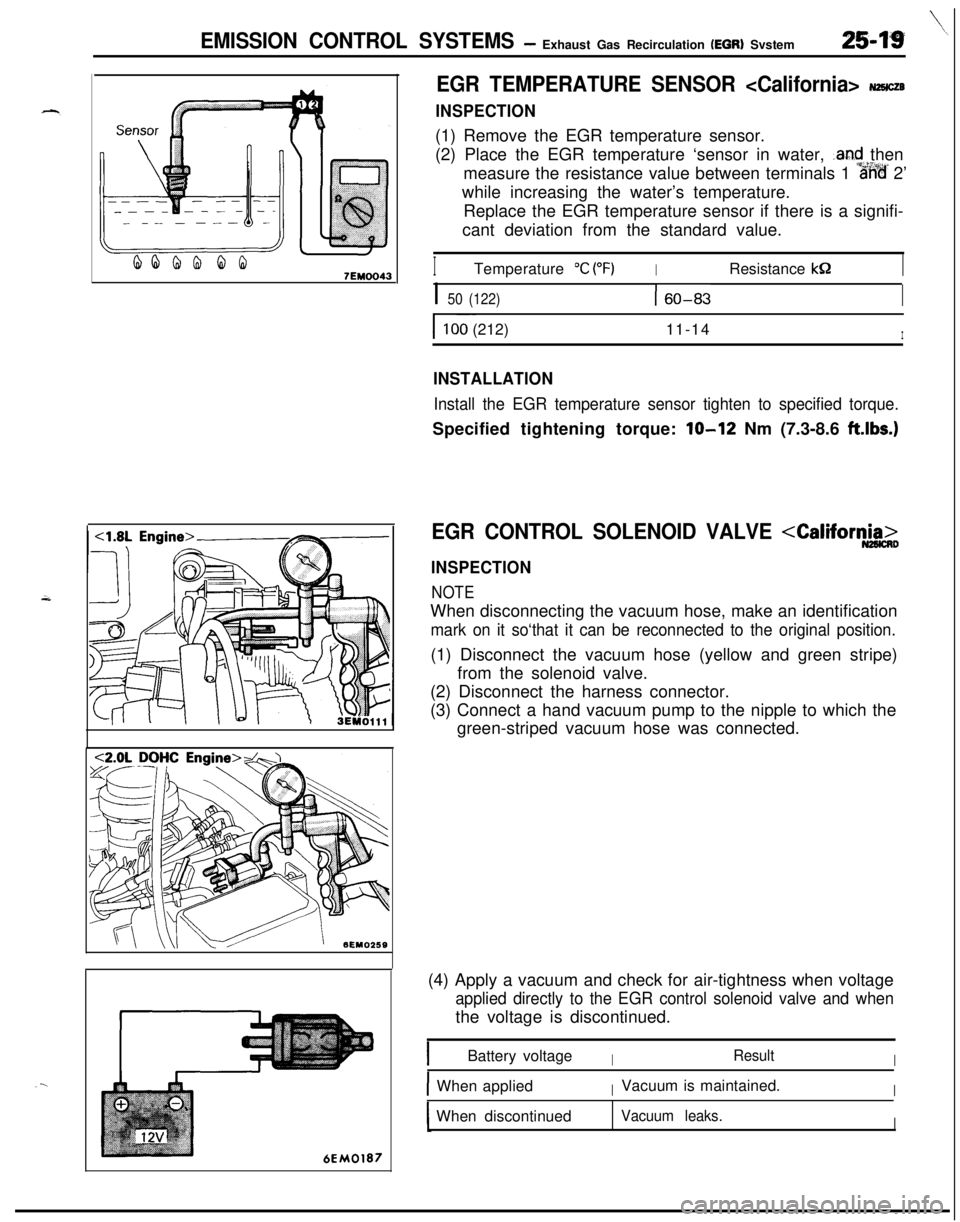
INSPECTION(1) Remove the EGR temperature sensor.
(2) Place the EGR temperature ‘sensor in water,
.and then
measure the resistance value between terminals 1
%%’ 2’
while increasing the water’s temperature.
Replace the EGR temperature sensor if there is a signifi-
cant deviation from the standard value.
ITemperature “C (“F)IResistance kS2I
I 50 (122)160-83I
I ~~100 (212)11-14I
INSTALLATION
Install the EGR temperature sensor tighten to specified torque.Specified tightening torque:
lo-12 Nm (7.3-8.6 ft.lbs.)
EGR CONTROL SOLENOID VALVE
INSPECTION
NOTEWhen disconnecting the vacuum hose, make an identification
mark on it so‘that it can be reconnected to the original position.(1) Disconnect the vacuum hose (yellow and green stripe)
from the solenoid valve.
(2) Disconnect the harness connector.
(3) Connect a hand vacuum pump to the nipple to which the
green-striped vacuum hose was connected.
(4) Apply a vacuum and check for air-tightness when voltage
applied directly to the EGR control solenoid valve and whenthe voltage is discontinued.
IBattery voltageIResultI
IWhen appliedIVacuum is maintained.IWhen discontinued
Vacuum leaks.I