Page 1112 of 1216
23-68BODY - Power Window
Power
window
lock
switch
,POWER WINDOW MOTOR
(1) Connect the motor terminal directly to the battery and
check to be sure that the slider moves smoothly.
(2) Also check to be sure that the slider moves in the opposite
direction when the battery polarity connections are
changed.CIRCUIT BREAKER (INCORPORATED IN THE POWER
WINDOW
MOTOR)
(1) Press the UP switch to fully close the window glass, and
continue to press the switch for
10 seconds.
(2) At the moment that the UP switch is released, press the
DOWN switch. The circuit breaker can be considered goodif at this time the door window glass begins to open within
60 seconds.POWER WINDOW MAIN SWITCH
Check for continuity in accordance to the following connection
table.
NOTEO-O indicates that there is continuity between the terminals.
Page 1115 of 1216

BODY - Central Door Locking System/Door Runchannel23-71View A
18A0064-
L
DOOR RUNCHANNEL
REMOVAL AND INSTALLATION
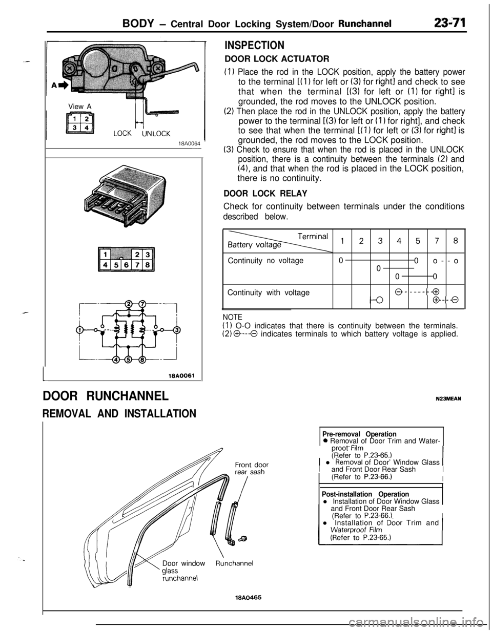
INSPECTIONDOOR LOCK ACTUATOR
(1) Place the rod in the LOCK position, apply the battery powerto the terminal
i(l) for left or (3) for right1 and check to see
that when the terminal
L(3) for left or (I) for right1 is
grounded, the rod moves to the UNLOCK position.
(2) Then place the rod in the UNLOCK position, apply the batterypower to the terminal
L(3) for left or (I 1 for right], and check
to see that when the terminal
[(l ) for left or (3) for right1 is
grounded, the rod moves to the LOCK position.
(3) Check to ensure that when the rod is placed in the UNLOCK
position, there is a continuity between the terminals
12) and
(41, and that when the rod is placed in the LOCK position,
there is no continuity.
DOOR LOCK RELAYCheck for continuity between terminals under the conditions
described below.
,2345, 8Continuity
novoltage0
0o--o
0
00
Continuity with voltage
@- -----@
@--0
NOTE
(1) O-O indicates that there is continuity between the terminals.
(2) O---O indicates terminals to which battery voltage is applied.
N23MEAN
Pre-removal Operation0 Removal of Door Trim and Water-
_ -..proot Mm
(Refer to
P.23-65.11 l Removal of Door’ Window Glass 1Iand Front Door Rear SashI(Refer to P.23-66.)IDoor window
runchannel
Post-installation Operationl Installation of Door Window Glass
and Front Door Rear Sash
(Refer to
P.23-66.1Il Installation of Dbor Trim and
Runchannel
18A0465
Page 1117 of 1216
BODY - Door Mirror/Electric Remote Controlled Mirror Switch23-73
18AO425
16P0109-
INSPECTION
ELECTRIC REMOTE CONTROLLED MIRROR ASSEMBLY
Check to be sure that the mirror moves as described in the tablewhen each terminal is connected to the battery.
DOWN0
0
00
RIGHT0
0
0
0
LEFT
IOI
ELECTRIC REMOTE CONTROLLED MIR-
ROR SWITCH
N23QAAN
INSPECTION
ELECTRIC REMOTE CONTROLLED MIRROR SWITCHOperate switches and check the continuity between terminals.
LEFT00
00
0
RIGHT00
NOTEO-O indicates that there is continuity between the terminals.
..
Page 1139 of 1216
BODY - Seat Belt23-9535-55 Nm
25-40 ft.lbs.\17-26 Nm
Shoulder belt removal steps
10. Guide ring
1 1. Shoulder beltc*12. Floor console assembly22. Outer switch connector connection
23. Retractor assembly (for shoulder belt)
19A0309
Buzzer removal stepsInstrument panel assembly24
(gy;ZfieerrtO P.23-80.)
NOTE(1) Reverse the removal procedures to reinstall.(2) +e : Refer to “Service Points of Removal”
19A0319
SERVICE POINTS OF REMOVAL
12. REMOVAL OF FLOOR CONSOLE ASSEMBLYRefer to
P.23-84.14. REMOVAL OF FRONT SEAT ASSEMBLY
Refer to
P.23-90.19. REMOVAL OF DOOR LATCH SWITCH
Refer to
P.23-69.
INSPECTION
MOTOR
(1) Unplug the automatic seat belt motor relay connector.
(2) Connect the terminals (indicated in the illustration) of the
automatic seat belt wiring harness connector directly to the
battery, and check that the motor operates smoothly. Next,reverse the polarity and check that the motor operates
smoothly in the reverse direction.
Page 1140 of 1216

23-96BODY - Seat Belt
Q ET19A0316
I) : Terminal to checkthe release switch
I+ : Terminal to check
the fasten switchlQA0316
16A07.51
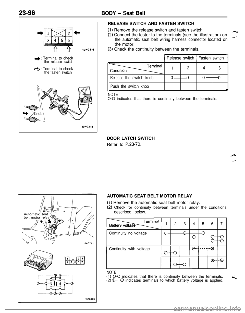
19PO363RELEASE SWITCH AND FASTEN SWITCH
(1) Remove the release switch and fasten switch.
(2) Connect the tester to the terminals (see the illustration) on*
the automatic seat belt wiring harness connector located on-’the motor.
(3) Check the continuity between the terminals.
11 Release switch 1 Fasten switch
Releasetheswitchknob
Push the switch knob
246000
0
NOTEO-O indicates that there is continuity between the terminals.
DOOR LATCH SWITCH
Refer to
P.23-70.AUTOMATIC SEAT BELT MOTOR RELAY
(1) Remove the automatic seat belt motor relay.
(2) Check for continuity between terminals under the conditions
described below.
Termi, lalIIBatterv voltaae
m-al1234567
Continuity no voltage
0
n 0”0
IContinuity with voltageIIIIIIII
NOTE(1) O-O indicates that there is continuity between the terminals.(2) O---O indicates terminals to which battery voltage is applied.
Page 1141 of 1216

BODY - Seat Belt23-97
4 : Terminal to check
outer switch IL.H.1
+ : Terminal to check
outer switch (R.H.1
lQPO36119A0322lQA0317
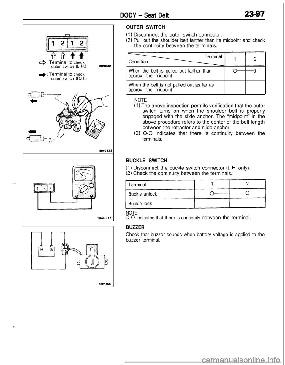
OUTER SWITCH
(1) Disconnect the outer switch connector.
(2) Pull out the shoulder belt farther than its midpoint and checkthe continuity between the terminals.
When the belt is pulled out farther than
approx. the midpoint00
When the belt is not pulled out as far as
approx. the midpoint
NOTE
(1) The above inspection permits verification that the outer
switch turns on when the shoulder belt is properly
engaged with the slide anchor. The “midpoint” in the
above procedure refers to the center of the belt length
between the retractor and slide anchor.
(2) O-O indicates that there is continuity between the
terminals.
BUCKLE SWITCH
(1) Disconnect the buckle switch connector (L.H. only).
(2) Check the continuity between the terminals.
)I
NOTEO-O indicates that there is continuity between the terminal.
BUZZER
Check that buzzer sounds when battery voltage is applied to the
buzzer terminal.
i
Page 1143 of 1216
BODY - Seat Belt23-99
19AO239
I ITest bulb 2tI
I I
INSPECTION
SEAT BELT TIMERRemove the seat belt timer from the relay box (indoor).
TIMER OPERATION CHECK(I
1 Connect the battery and the test bulb to the timer, as shown
in the illustration.
(2) Make sure that when terminal 2 is connected to the positive
(+) terminal of the battery, test bulbs 1 and 2 are lighted
for approx. 6 seconds.
(3) Make sure that even when terminal 3 is disconnect while testbulbs 1 and 2 and lighted in
(2) above, test bulb 1 remains
lighted.
BUCKLE SWITCHRefer to
P.23-97.
BUZZERRefer to
P.23-97.
SERVICE POINTS OF INSTALLATION7. INSTALLATION OF FRONT SEAT BELT
Fit the retractor retaining lug in the slot provided in the
vehicle body, and secure the retractor with the bolt by
tightening it to the specified torque.
Page 1148 of 1216

24-4HEATERS AND AIR CONDITIONING - Troubleshooting
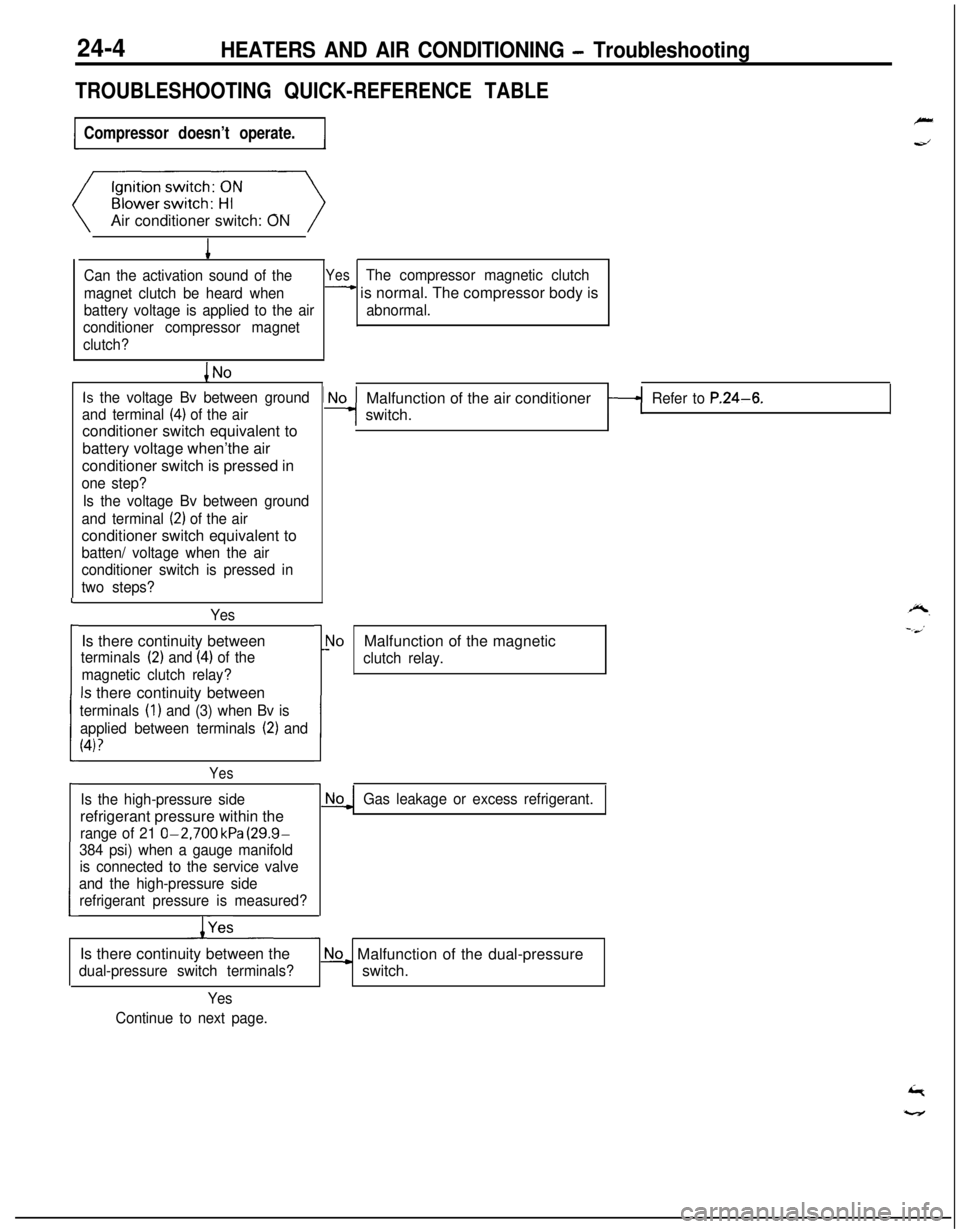
TROUBLESHOOTING QUICK-REFERENCE TABLE
Compressor doesn’t operate.Air conditioner switch: ON
1
Can the activation sound of theYesThe compressor magnetic clutch
magnet clutch be heard when
- is normal. The compressor body is
battery voltage is applied to the airabnormal.
conditioner compressor magnet
clutch?
Is the voltage Bv between ground
and terminal
(4) of the airconditioner switch equivalent to
battery voltage when’the air
conditioner switch is pressed in
one step?
Is the voltage Bv between ground
and terminal
(2) of the airconditioner switch equivalent to
batten/ voltage when the air
conditioner switch is pressed in
two steps?
YesIs there continuity between
terminals (2) and (4) of the
magnetic clutch relay?
Is there continuity between
terminals (1) and (3) when Bv is
applied between terminals
(2) and
(4)?
L
i
I
Yes
Is the high-pressure siderefrigerant pressure within the
range of 21 O-2,700 kPa (29.9-
384 psi) when a gauge manifold
is connected to the service valve
and the high-pressure side
refrigerant pressure is measured?
/YesMalfunction of the air conditioner
switch.
Refer to P.24-6.
r
1!
\loMalfunction of the magnetic
clutch relay.
Gas leakage or excess refrigerant.Is there continuity between the
dual-pressure switch terminals?
No_ Malfunction of the dual-pressure
switch.
Yes
Continue to next page.