Page 897 of 1216
AUTOMATIC TRANSAXLE - Troubleshooting21-203
CIRCUIT DIAGRAM
J/B
63IOA
0
'13l-----AWD1
cL
13 C-67
1
'OU'EiRaPPLl
--b
7
1'
I
I
3
xl:- 71
03
4
I
L--
-----------------16 C-502zs
4
C-58
El
THEFT-ALARM
CONTROL UNIT
INHIBITORSWITCH
B-25
r
STARTER MOTOR
X35-AC-U0705-NC
Page 919 of 1216

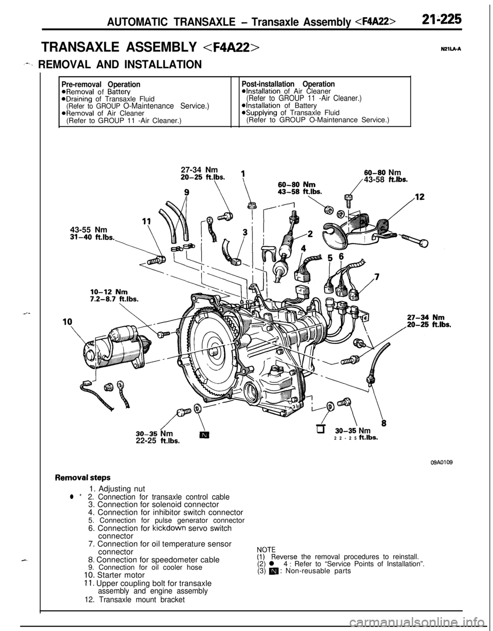
AUTOMATIC TRANSAXLE - Transaxle Assembly 21"225
TRANSAXLE ASSEMBLY N2ll.A.A
,--. REMOVAL AND INSTALLATION
Pre-removal OperationPost-installation Operation@Removal of Battew@Installation of Air CleaneraDraining of Transaxle Fluid(Refer to GROUP 11 -Air Cleaner.)(Refer to GROUP O-Maintenance Service.)@Installation of BatteryaRemoval of Air Cleaner*Supplying of Transaxle Fluid
(Refer to GROUP 11 -Air Cleaner.)(Refer to GROUP O-Maintenance Service.)
27-34 Nm20-25
ftlbs.
1143-55 Nm31-40
ft.lbs.-\60-80
flrn60-80 Nm/43-58 ft.lbs.
//\-LTT \.30-35 Nm
AIq 30-35 Nm22-25 klbs.22-25 ft.lbs.
09A0109
Removal steps1. Adjusting nut
l *2. Connection for transaxle control cable3. Connection for solenoid connector
4. Connection for inhibitor switch connector
5. Connection for pulse generator connector
6. Connection for kickdown servo switch
connector
7. Connection for oil temperature sensor
connector
8. Connection for speedometer cable
9. Connection for oil cooler hose
10. Starter motor
11. Upper coupling bolt for transaxleassembly and engine assembly
12. Transaxle mount bracket
$?everse the removal procedures to reinstall.
(2) l 4 : Refer to “Service Points of Installation”.
(3) m : Non-reusable parts
Page 953 of 1216

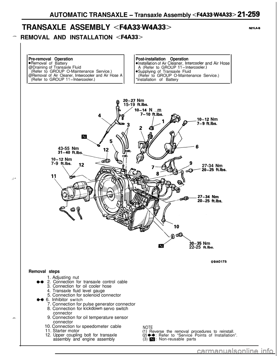
AUTOMATIC TRANSAXLE - Transaxle Assembly 21-259
TRANSAXLE ASSEMBLY
- REMOVAL AND INSTALLATION N2ll.kB
Pre-removal OperationPost-installation Operation*Removal of Battery*Installation of Air Cleaner, Intercooler and Air Hose@Draining of Transaxle Fluid
A (Refer to GROUP II-Intercooler.)(Refer to GROUP O-Maintenance Service.)
@Removal of Air Cleaner, Intercooler and Air Hose A*Supplying of Transaxle Fluid
(Refer to GROUP O-Maintenance Service.)
(Refer to GROUP II-Intercooler.)*Installation of Battery20-27 Nm
15-19
ft.lbs.
/ IO-14 Nm
43-55 Nm31-40
ft.lbs.
lo-12 Nm
7-9 f?.lbs.
___.Ibs.
lo-12 Nm-7-9 fi.lbs.27-34 Nm20-25
ft.lbs.30-35 Nm
22-25
ft.lbs.
09A0175
Removal steps
1. Adjusting nut+42. Connection for transaxle control cable
3. Connection for oil cooler hose
4. Transaxle fluid level gauge5. Connection for solenoid connector
e+ 6. Inhibitor switch
7. Connection for pulse generator connector
8. Connection for kickdown servo switch
connector9. Connection for oil temperature sensor
connector
10. Connection for speedometer cable
11. Starter motor
12. Upper coupling bolt for transaxle
assembly and engine assembly
NOTE(1) Reverse the removal procedures to reinstall.(2) I)+ : Refer to “Service Points of Installation”.
(3) m : Non-reusable parts
Page 955 of 1216
AUTOMATIC TRANSAXLE - Transaxle Assembly 21 kz6’1
REMOVAL AND INSTALLATION N2llA-C
(Refer to GROUP
II-Intercooler.)43-55 Nm
\i 513 \20-27 Nm
Q15-19 ft.lbs.
lo-14 NmIO-12 Nm10 ft.lbs.7-9 ftlbs.
/27-34 Nm
ft.lbs.
Y
Es.
Removal steps1. Adjusting nut
l 42. Connection for transaxle control cable3. Connection for oil cooler hose
4. Transaxle fluid level gauge5. Connection for solenoid connector
l +6. Connection for inhibitor switch connector7. Connection for pulse generator connector8. Connection for kickdown servo switch
connector9. Connection for oil temperature sensor
OQAOl63connector
10. Connection for speedometer cable11. Starter motor12. Upper coupling bolt for transaxle
assembly and engine assembly
irkeverse the removal procedures to reinstall.
(2) I)+ : Refer to “Service Points of Installation”
(3) m : Non-reusable parts
Page:
< prev 1-8 9-16 17-24