1991 MITSUBISHI ECLIPSE Starter
[x] Cancel search: StarterPage 713 of 1216

MANUAL TRANSAXLE
TRANSAXLE
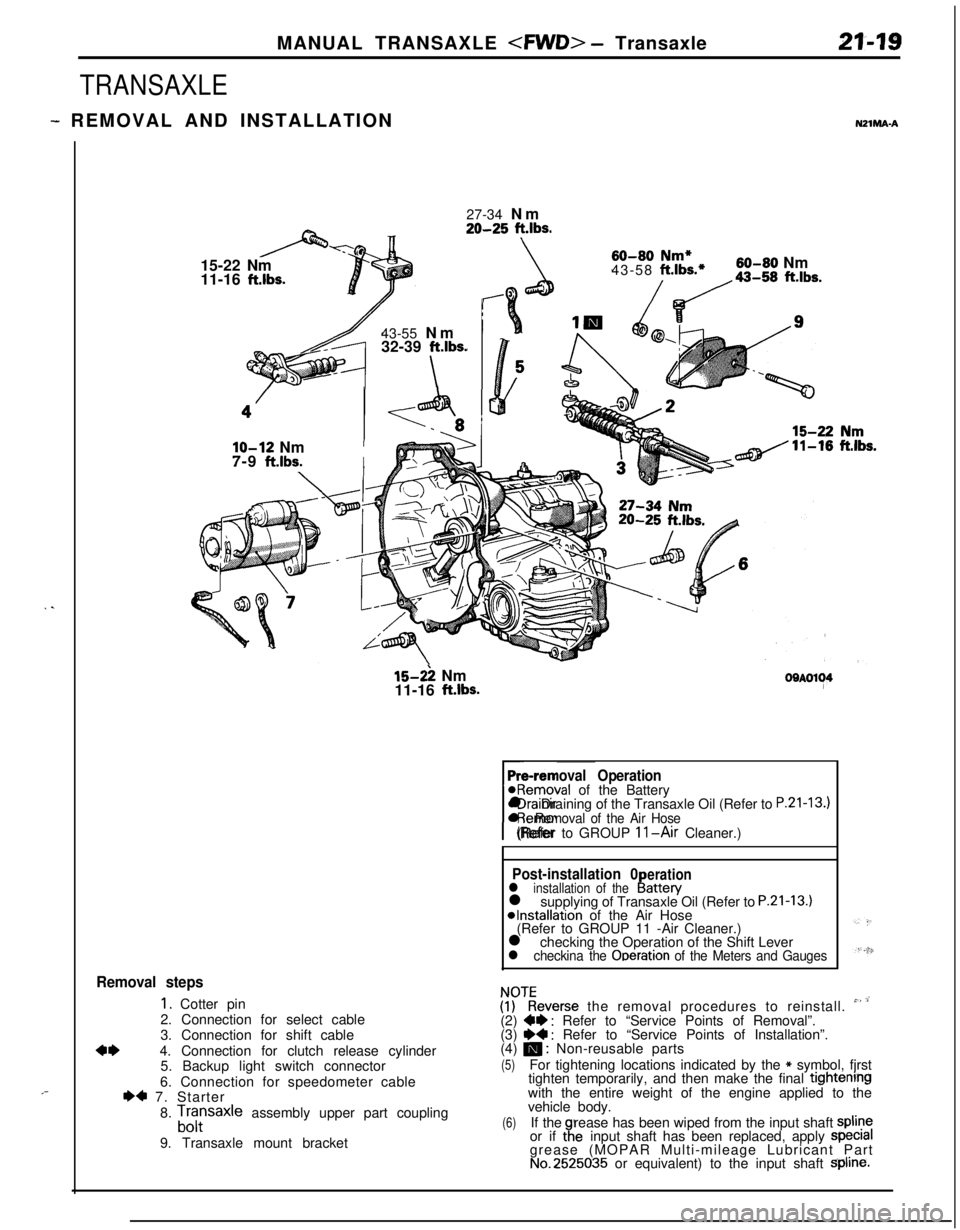
- REMOVAL AND INSTALLATIONNZlMA-A
. .
,-27-34 Nm
20-25 ft.lbs.15-22 Nm
11-16
ft.lbs.43-55 Nm
32-39
ft.lbs.
\
60-80 Nm*43-58 ft.lbs.*60-80 Nm
/da-,, ft.lbs.
lo-12 NmI7-9
ft.lbs.I
15-2: Nm
11-16 ft.lbs.OOAOl~4
Pre-removal Operation@Removal of the Battery
rl Draining of the Transaxle Oil (Refer to
P.21-13.)l Removal of the Air Hose(Refer to GROUP 11-Air Cleaner.)
Post-installation 0erationl installation of theI!attery
l supplying of Transaxle Oil (Refer to P.21-13.)*Installation of the Air Hose
(Refer to GROUP 11 -Air Cleaner.)
l checking the Operation of the Shift Lever
l checkina the Ooeration of the Meters and Gauges
Removal steps
1. Cotter pin
2. Connection for select cable
3. Connection for shift cable
4*4. Connection for clutch release cylinder
5. Backup light switch connector
6. Connection for speedometer cable
I)* 7. Starter
8.
Lfrsaxle assembly upper part coupling
9. Transaxle mount bracket
ZKeverse the removal procedures to reinstall. ” ’(2) W : Refer to “Service Points of Removal”.
(3) ~~ : Refer to “Service Points of Installation”.
(4) m : Non-reusable parts
(5)For tightening locations indicated by the * symbol, fjrst
tighten temporarily, and then make the final tightenrngwith the entire weight of the engine applied to the
vehicle body.
(6)If therease has been wiped from the input shaft spline
or if taeinput shaft has been replaced, apply specralgrease (MOPAR Multi-mileage Lubricant Part
No.2525035 or equivalent) to the input shaft Spline.
Page 716 of 1216

21-22MANUAL TRANSAXLE
1 Transaxleside1 Radiator lower hose
1 Transaxle side1 Radiator lower hosepart ofdrive shaft
I
-Transaxle
09LOO5819. REMOVAL OF TRANSAXLE ASSEMBLY
Caution
On the turbo vehicle, take care to prevent damaging
+Gthe lower hose of the radiator with the end of the
’transaxle housing.
As a protective countermeasure, wind tape around the
lower hose and the transaxle housing at the positions
shown in the figure.
Support the transaxle assembly by using a transaxle jack;
then, after moving the transaxle assembly to the right,
lower it.
NOTEWhen supporting the transaxle assembly by the transaxle
jack, take care to be sure that the jack’s force is applied to awide area, not to only a small localized area.
SERVICE POINTS OF INSTALLATION
NZlMDAP19. INSTALLATION OF TRANSAXLE ASSEMBLY
Caution
On the turbo vehicle, take care to prevent damaging
Athe lower hose of the radiator with the end of the
-transaxle housing.
As a protective countermeasure, wind tape around the
lower hose and the transaxle housing at the positions
shown in the figure.
15. INSTALLATION OF DRIVE SHAFT
(1) Provisionally install the drive shaft so that the inboard
joint part of the drive shaft is straight, and not bent
relative to the transaxle.
Caution
Care must be taken to ensure that the oil seal lip
part of the transaxle is not damaged by the serratedpart of the drive shaft.
(2) Align the serrations and securely insert the drive shaft
into the transaxle.
7. INSTALLATION OF STARTER
Tighten the starter installation bolts with the wiring harness
clip and the ground cable.
Page 768 of 1216

21-74MANUAL TRANSAXLE
Part nameThickness mm (in.)Identification
symbolPart No.
Spacer
1.61
(.0634)61MD722094(For adjustment of driven bevel gear trainpreload)
1.64
(.0646)64MD7220951.67
(0657)67MD722096
1.70(.0669)70MD7220971.73
(0681)73MD7220981.76
(.0693)76M D7220991.79
(0705)79MD7221 00
1.82
(0717)82MD7221 011.85
(.0328)85MD7221 02
1.88
(.0740)88MD7221 03
1.91
(.0752)91MD7221 04
1.94
(0764)94MD722105Spacer
0.13
(0051)13MD720353(For adjustment Of driven bevel gear
mOWIt)o,16 ( 0063)16M D7203540.19
(0075)19MD7203550.22
(.0087)22MD7203560.25
(.0098)25MD7203570.28(.Ol
IO)28MD7203580.31
(0122)31MD7203590.34
(0134)34MD7203600.37
(0146)37MD7203610.40
(0517)40M D7203620.43
(.0169)43MD7203630.46
(0181)46MD7203640.49
(.0193)49MD7203650.52
(0205)52MD720366
TORQUE SPECIFICATIONSNZlCC-B
TRANSAXLEItems
Bell housing cover mounting bolt
Starter motor mounting bolt
Transaxle mount bracket mounting bolt
Shift cable and select cable bracket mounting bolt
Rear cover mounting bolt
Transaxle case mounting bolt
Clutch release cylinder mounting bolt
Clutch tube to transaxle assembly
Under cover
Transaxle mounting bolt
[I2 mm (47 in.) diameter bolt]
Transaxle mounting bolt [IO mm
(40 in.) diameter bolt]
Transaxle mounting bolt [8 mm (.31 in.) diameter bolt]
Tie rod end to knuckleNm
ft.lbs.
IO-127-9
27-34
20-25
60-8043-58
15-22
11-1635-42
26-3035-42
26-3015-22
11-1615-22
11-169-13
7-1043-55
32-39
30-3522-25
IO-127-9
24-3517-25
Page 776 of 1216

21-82MANUAL TRANSAXLE
TRANSAXLE
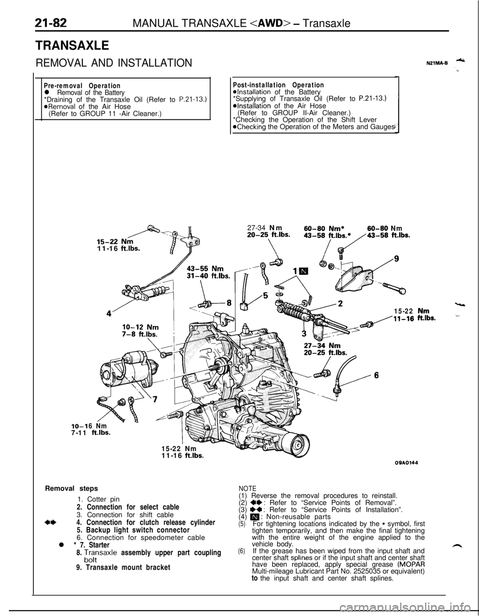
REMOVAL AND INSTALLATION
Pre-removal Operationl Removal of the Battery*Draining of the Transaxle Oil (Refer to P.Zl-13.)
@Removal of the Air Hose
(Refer to GROUP 11 -Air Cleaner.)IO-1
7-1111-16
ftlbs.
Post-installation Operation@Installation of the Battery
*Supplying of Transaxle Oil (Refer to P.21-13.)*Installation of the Air Hose
(Refer to GROUP II-Air Cleaner.)
*Checking the Operation of the Shift Lever
@Checking the Operation of the Meters and Gauges
27-34 Nm
60-60 Nm*60-80 Nm20-25 ft.lbs.
\
43-58/t.,b~43-58 ft.lbs.
15-22
6 Nm
ftlbs.
15-22 Nm
vt11-16
ft.lbs.Removal steps
1. Cotter pin
2. Connection for select cable
3. Connection for shift cable
*I)4. Connection for clutch release cylinder
5. Backup light switch connector
6. Connection for speedometer cable
l * 7. Starter
8.
A;;saxle assembly upper part coupling
9. Transaxle mount bracket
NZlMA-B -
,“rr,s.
09AOl44
NOTE(1) Reverse the removal procedures to reinstall.
(2)
+e : Refer to “Service Points of Removal”.
(3) I)+ : Refer to “Service Points of Installation”.
(4) m : Non-reusable parts(5)For tightening locations indicated by the * symbol, first
tighten temporarily, and then make the final tightening
with the entire weight of the engine applied to the
(6)vehicle body.
If the grease has been wiped from the input shaft and
center shaft splines or if the input shaft and center shaft
have been replaced, apply special grease
(MOPARMulti-mileage Lubricant Part No. 2525035 or equivalent)
to the input shaft and center shaft splines.
Page 778 of 1216

21-84MANUAL TRANSAXLE
r) ’TransaxlellKfil1
SERVICE POINTS OF REMOVALN21MBAV4. DISCONNECTION OF CLUTCH RELEASE CYLINDER/
12. TIE ROD
END/l4. LOWER ARM BALL JOINT
Refer to
P.21-21.15. DISCONNECTION OF DRIVE SHAFT
shaft, and then pry the drive shaft from the transaxle.
Caution
1.Do not pull on the drive shaft; doing so will damage
the inboard joint; be sure to use the pry bar.
2.Do not insert the pry bar so deep as to damaged theoil seal.
(1) Take out the drive shaft by lightly tapping the drive shaftT.J. case with a plastic hammer.
NOTERemove the drive shaft with the hub and knuckle, etc.,
as an assembly.
Caution
1. Removing the drive shaft from the,, outboa,rd
joint side can cause damage to the inboard joint.Always use a plastic hammer, etc., to remove
the drive shaft.
2. Tapping on the center bearing can damage it.
Never tap on the bearing.
(2) Keep the removed drive shaft as far away from the
transaxle case as possible, and secure (by using rope,
etc.) the joints to the body so that it does not fall.
17. REMOVAL OF FRONT EXHAUST PIPE
Refer to GROUP
1 l-Exhaust Pipe and Main Muffler.
18. REMOVAL OF TRANSFER ASSEMBLY
Refer to
P.21-85.23. REMOVAL OF TRANSAXLE ASSEMBLY
Refer to
P.21-22.
SERVICE POINTS OF INSTALLATION!’23. REMOVAL OF TRANSAXLE ASSEMBLY
Refer to
P.21-22.15. INSTALLATION OF DRIVE SHAFT
Refer to
P.21-22.7. INSTALLATION OF STARTER
Refer to
P.21-22.
NZlMDAQ
Page 860 of 1216

21-166AUTOMATIC TRANSAXLE - SDecifications
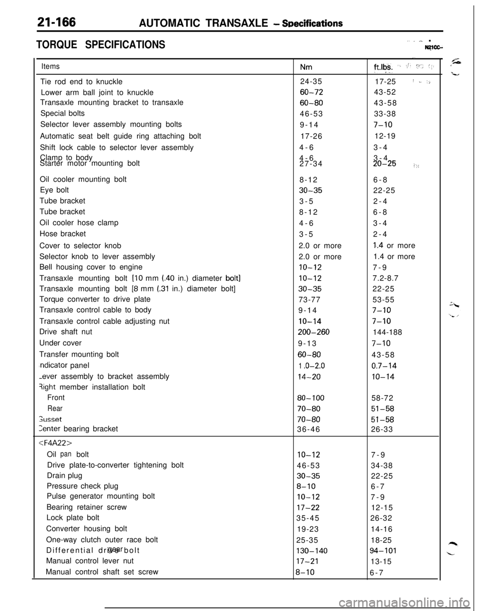
TORQUE SPECIFICATIONS,. _ ,,,_ .Nglcc-
ItemsTie rod end to knuckle
Lower arm ball joint to knuckle
Transaxle mounting bracket to transaxle
Special bolts
Selector lever assembly mounting bolts
Automatic seat belt guide ring attaching bolt
Shift lock cable to selector lever assembly
Clamp to body
Starter motor mounting bolt
Oil cooler mounting bolt
Eye bolt
Tube bracket
Tube bracket
Oil cooler hose clamp
Hose bracket
Cover to selector knob
Selector knob to lever assembly
Bell housing cover to engine
Transaxle mounting bolt
[lo mm l.40 in.) diameter bolt]Transaxle mounting bolt
[8 mm I.31 in.) diameter bolt]
Torque converter to drive plate
Transaxle control cable to body
Transaxle control cable adjusting nut
Drive shaft nut
Under cover
Transfer mounting boltndicator panel-ever assembly to bracket assembly
3ight member installation bolt
Front
Rear
;usset
Zenter bearing bracket
:l=4A22>Oil bolt
panDrive plate-to-converter tightening bolt
Drain plug
Pressure check plug
Pulse generator mounting bolt
Bearing retainer screw
Lock plate bolt
Converter housing bolt
One-way clutch outer race bolt
Differential drive bolt
gearManual control lever nut
Manual control shaft set screw
Nm24-35
60-72
60-8046-53
9-14
17-26
4-6
4-6
27-34
8-12
30-353-5
8-12
4-6
3-5
2.0 or more
2.0 or more
10-12
10-12
30-3573-77
9-14
IO-14
200-2609-13
60-80
1 .o-2.0
14-20
80- 100
70-80
70-8036-46
10-1246-53
30-35
8-10
IO-12
17-2235-45
19-23
25-35
130-14017-21
8-10
-.
ft*lgk+ ‘. St. :“.. (1.17-25
I ~. ‘,43-52
43-58
33-38
7-1012-19
3-4
3-4
20-25i::6-8
22-25
2-4
6-8
3-4
2-4
1..4 or more
1.4 or more
7-9
7.2-8.7
22-25
53-55
7-10
7-10144-188
7-1043-58
0.7-14
10-1458-72
51-58
51-5826-33
7-9
34-38
22-25
6-7
7-9
12-15
26-32
14-16
18-25
94-10113-15
6-7
Page 872 of 1216

21-178AUTOMATIC TRANSAXLE - Troubleshooting
09P0010Fluid level must be
within this range.09PoOll
0”
Two302
DIAGNOSIS AND TEST
FLUID LEVEL AND CONDITION1. Drive until the fluid temperature reaches the usual tem-
perature
[70-80°C (160- 18O”F)I.2. Place vehicle on level floor.
3. Move selector lever sequentially to every position to fill
torque converter and hydraulic circuit with fluid, then place
lever in “N” Neutral position. This operation is necessary tobe sure that fluid level check is accurate.
4. Before removing dipstick, wipe all dirt from area around
dipstick. Then take out the dipstick and check the conditionof the fluid.
The transaxle should be overhauled under the following
conditions.l If there is a “burning” odor.
l If the fluid color has become noticeably blacker.
lIf there is a noticeably great amount of metal particles inthe fluid.
5.Check to see if fluid level is in “HOT” range on dipstick. If
fluid level is low, add automatic transaxle fluid until level
reaches “HOT” range.
Low fluid level can cause a variety of conditions because itallows pump to take in air along with fluid. Air trapped in
hydraulic circuit forms bubbles which make fluid spongy.
Therefore, pressures will be erratic.
Improper filling can also raise fluid level too high. When
transaxle has too much fluid, gears churn up foam and
cause same conditions which occur with low fluid level,
resulting in accelerated deterioration of automatic transaxle
fluid.In either case, air bubbles can cause overheating, fluid
oxidation, which can interfere with normal valve, clutch,
and servo operation. Foaming can also result in fluid
escaping from transaxle vent where it may be mistaken for
a leak.
6. Be sure to examine fluid on dipstick closely.
CONTROL CABLE
Whether control cable is properly adjusted can be confirmed bychecking whether inhibitor switch is performing well.
1. Apply parking brakes and service brakes securely.
2. Place selector lever to “R” range.
3. Set ignition key to “ST” position.
4. Slowly move the selector lever upward until it clicks as it
fits in notch of “P” range. If starter motor operates when
lever makes a click, “P” position is correct.
5.Then slowly move selector lever to “N” range by the same
procedure as in foregoing paragraph. If starter motor
operates when selector lever fits in “N”, “N” position is
correct.6. Also check to be sure the vehicle doesn’t begin to move
and the lever doesn’t stop between P-R-N-D.
7. The control cable is properly adjusted if, as described
above, the starter motor starts at both the “P” range and
the “N” range.
Page 896 of 1216

21-202AUTOMATIC TRANSAXLE - Troubleshooting
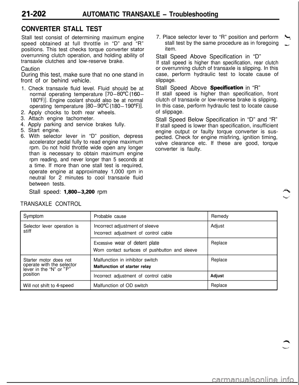
CONVERTER STALL TESTStall test consist of determining maximum engine
speed obtained at full throttle in “D” and “R”
positions. This test checks torque converter stator
overrunning clutch operation, and holding ability of
transaxle clutches and low-reserve brake.
CautionDuring this test, make sure that no one stand in
front of or behind vehicle.
1. Check transaxle fluid level. Fluid should be at
normal operating temperature
[70-80°C (160-
18O”F)]. Engine coolant should also be at normaloperating temperature
[80-90°C (180- 19O”F)l.2. Apply chocks to both rear wheels.
3. Attach engine tachometer.
4. Apply parking and service brakes fully.
5. Start engine.
6. With selector lever in “D” position, depress
accelerator pedal fully to read engine maximum
rpm. Do not hold throttle wide open any longer
than is necessary to obtain maximum engine
rpm reading, and never longer than 5 seconds ata time. If more than one stall test is required,
operate engine at approximatey 1,000 rpm in
neutral for 2 minutes to cool transaxle fluid
between tests.
Stall speed:
1,800-3,200 rpm
TRANSAXLE CONTROL7. Place selector lever to “R” position and perform
?+stall test by the same procedure as in foregoing
-,
item.Stall Speed Above Specification in “D”
If stall speed is higher than specification, rear clutchor overrunning clutch of transaxle is slipping. In this
case, perform hydraulic test to locate cause of
slippage.Stall Speed Above Specifjcation in “R”
If stall speed is higher than specification, front
clutch of transaxle or low-reverse brake is slipping.
In this case, perform hydraulic test to locate cause
of slippage.
Stall Speed Below Specification in “D” and “R”
If stall speed is lower than specification, insufficient
engine output or faulty torque converter is sus-
pected. Check for engine misfiring, ignition timing,
valve clearance etc. If these are good, torque
converter is faulty.
Symptom
Selector lever operation isstiff
Probable causeIncorrect adjustment of sleeve
Incorrect adjustment of control cable
Excessive wear of detent plate
Worn contact surfaces of pushbutton and sleeveRemedyAdjust
Replace
Starter motor does notoperate with the selector
lever in the “N” or
“P”position
Will not shift to
4-speedMalfunction in inhibitor switch
Malfunction of starter relay
Incorrect adjustment of control cableMalfunction of OD switch
Replace
Adjust
Replace