Page 713 of 1216
MANUAL TRANSAXLE - Transaxle21-19
TRANSAXLE
- REMOVAL AND INSTALLATIONNZlMA-A
. .
,-27-34 Nm
20-25 ft.lbs.15-22 Nm
11-16
ft.lbs.43-55 Nm
32-39
ft.lbs.
\
60-80 Nm*43-58 ft.lbs.*60-80 Nm
/da-,, ft.lbs.
lo-12 NmI7-9
ft.lbs.I
15-2: Nm
11-16 ft.lbs.OOAOl~4
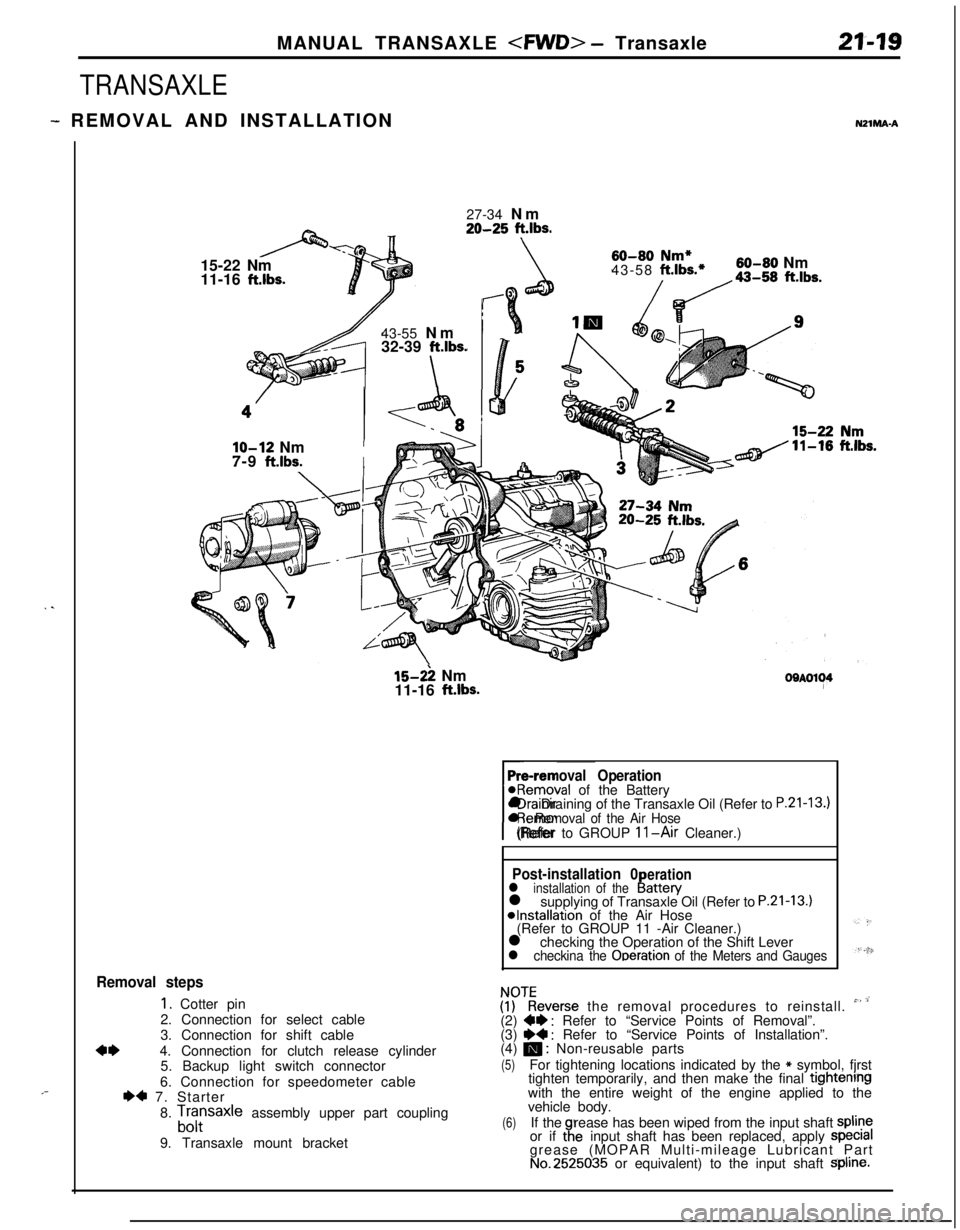
Pre-removal Operation@Removal of the Battery
rl Draining of the Transaxle Oil (Refer to
P.21-13.)l Removal of the Air Hose(Refer to GROUP 11-Air Cleaner.)
Post-installation 0erationl installation of theI!attery
l supplying of Transaxle Oil (Refer to P.21-13.)*Installation of the Air Hose
(Refer to GROUP 11 -Air Cleaner.)
l checking the Operation of the Shift Lever
l checkina the Ooeration of the Meters and Gauges
Removal steps
1. Cotter pin
2. Connection for select cable
3. Connection for shift cable
4*4. Connection for clutch release cylinder
5. Backup light switch connector
6. Connection for speedometer cable
I)* 7. Starter
8.
Lfrsaxle assembly upper part coupling
9. Transaxle mount bracket
ZKeverse the removal procedures to reinstall. ” ’(2) W : Refer to “Service Points of Removal”.
(3) ~~ : Refer to “Service Points of Installation”.
(4) m : Non-reusable parts
(5)For tightening locations indicated by the * symbol, fjrst
tighten temporarily, and then make the final tightenrngwith the entire weight of the engine applied to the
vehicle body.
(6)If therease has been wiped from the input shaft spline
or if taeinput shaft has been replaced, apply specralgrease (MOPAR Multi-mileage Lubricant Part
No.2525035 or equivalent) to the input shaft Spline.
Page 776 of 1216
21-82MANUAL TRANSAXLE - Transaxle
TRANSAXLE
REMOVAL AND INSTALLATION
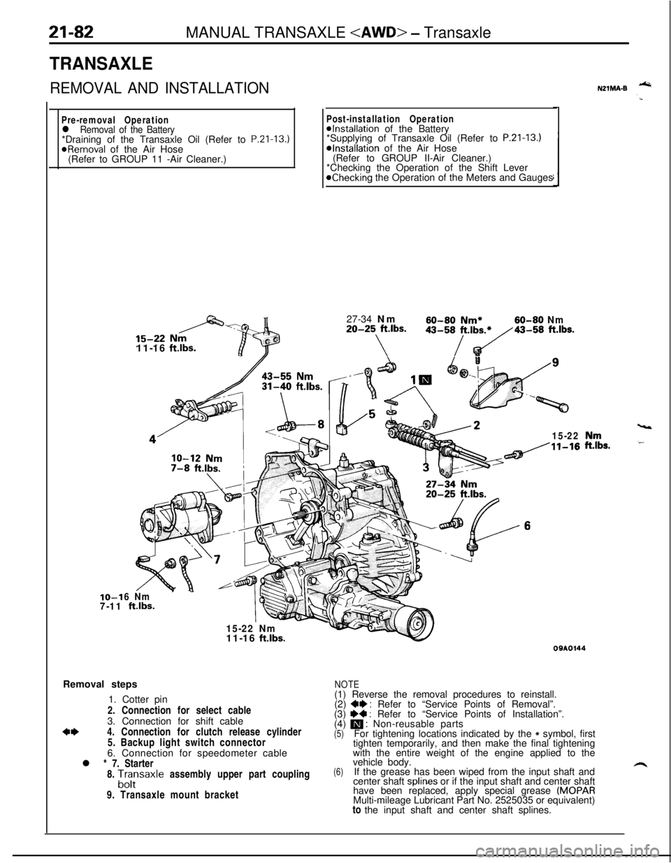
Pre-removal Operationl Removal of the Battery*Draining of the Transaxle Oil (Refer to P.Zl-13.)
@Removal of the Air Hose
(Refer to GROUP 11 -Air Cleaner.)IO-1
7-1111-16
ftlbs.
Post-installation Operation@Installation of the Battery
*Supplying of Transaxle Oil (Refer to P.21-13.)*Installation of the Air Hose
(Refer to GROUP II-Air Cleaner.)
*Checking the Operation of the Shift Lever
@Checking the Operation of the Meters and Gauges
27-34 Nm
60-60 Nm*60-80 Nm20-25 ft.lbs.
\
43-58/t.,b~43-58 ft.lbs.
15-22
6 Nm
ftlbs.
15-22 Nm
vt11-16
ft.lbs.Removal steps
1. Cotter pin
2. Connection for select cable
3. Connection for shift cable
*I)4. Connection for clutch release cylinder
5. Backup light switch connector
6. Connection for speedometer cable
l * 7. Starter
8.
A;;saxle assembly upper part coupling
9. Transaxle mount bracket
NZlMA-B -
,“rr,s.
09AOl44
NOTE(1) Reverse the removal procedures to reinstall.
(2)
+e : Refer to “Service Points of Removal”.
(3) I)+ : Refer to “Service Points of Installation”.
(4) m : Non-reusable parts(5)For tightening locations indicated by the * symbol, first
tighten temporarily, and then make the final tightening
with the entire weight of the engine applied to the
(6)vehicle body.
If the grease has been wiped from the input shaft and
center shaft splines or if the input shaft and center shaft
have been replaced, apply special grease
(MOPARMulti-mileage Lubricant Part No. 2525035 or equivalent)
to the input shaft and center shaft splines.
Page 860 of 1216
21-166AUTOMATIC TRANSAXLE - SDecifications
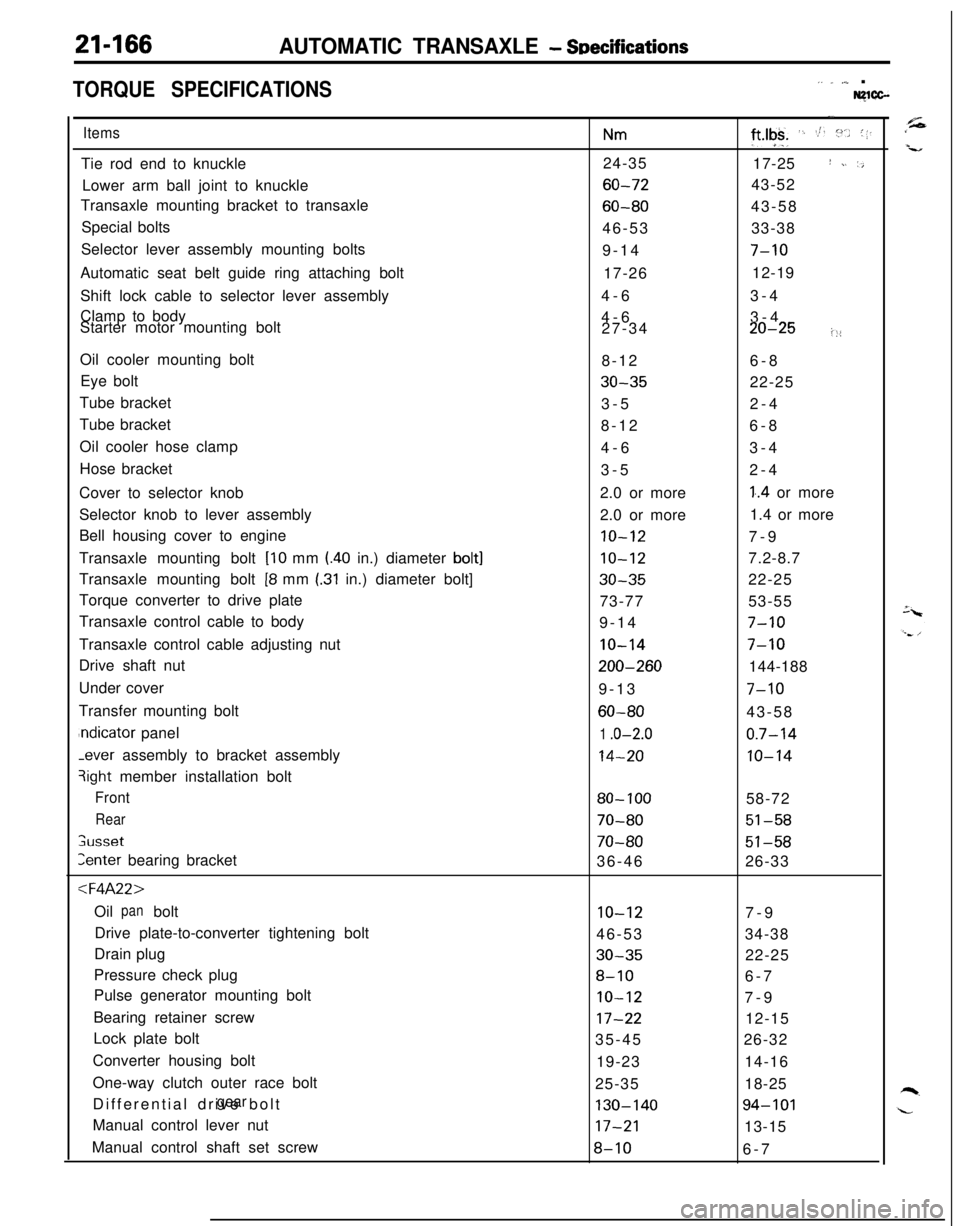
TORQUE SPECIFICATIONS,. _ ,,,_ .Nglcc-
ItemsTie rod end to knuckle
Lower arm ball joint to knuckle
Transaxle mounting bracket to transaxle
Special bolts
Selector lever assembly mounting bolts
Automatic seat belt guide ring attaching bolt
Shift lock cable to selector lever assembly
Clamp to body
Starter motor mounting bolt
Oil cooler mounting bolt
Eye bolt
Tube bracket
Tube bracket
Oil cooler hose clamp
Hose bracket
Cover to selector knob
Selector knob to lever assembly
Bell housing cover to engine
Transaxle mounting bolt
[lo mm l.40 in.) diameter bolt]Transaxle mounting bolt
[8 mm I.31 in.) diameter bolt]
Torque converter to drive plate
Transaxle control cable to body
Transaxle control cable adjusting nut
Drive shaft nut
Under cover
Transfer mounting boltndicator panel-ever assembly to bracket assembly
3ight member installation bolt
Front
Rear
;usset
Zenter bearing bracket
:l=4A22>Oil bolt
panDrive plate-to-converter tightening bolt
Drain plug
Pressure check plug
Pulse generator mounting bolt
Bearing retainer screw
Lock plate bolt
Converter housing bolt
One-way clutch outer race bolt
Differential drive bolt
gearManual control lever nut
Manual control shaft set screw
Nm24-35
60-72
60-8046-53
9-14
17-26
4-6
4-6
27-34
8-12
30-353-5
8-12
4-6
3-5
2.0 or more
2.0 or more
10-12
10-12
30-3573-77
9-14
IO-14
200-2609-13
60-80
1 .o-2.0
14-20
80- 100
70-80
70-8036-46
10-1246-53
30-35
8-10
IO-12
17-2235-45
19-23
25-35
130-14017-21
8-10
-.
ft*lgk+ ‘. St. :“.. (1.17-25
I ~. ‘,43-52
43-58
33-38
7-1012-19
3-4
3-4
20-25i::6-8
22-25
2-4
6-8
3-4
2-4
1..4 or more
1.4 or more
7-9
7.2-8.7
22-25
53-55
7-10
7-10144-188
7-1043-58
0.7-14
10-1458-72
51-58
51-5826-33
7-9
34-38
22-25
6-7
7-9
12-15
26-32
14-16
18-25
94-10113-15
6-7
Page 869 of 1216
AUTOMATIC TRANSAXLE - TroubleshootingBased upon use of the troubleshooting
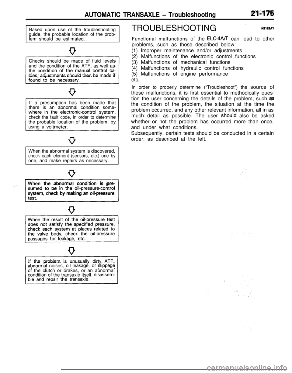
guide, the probable location of the prob-
lem should be estimated.
Checks should be made of fluid levels
and the condition of the ATF, as well as
bles; adjustments should then be made if
If a presumption has been made that
there is an abnormal condition some-
check the fault code, in order to determinethe probable location of the problem, by
When the abnormal system is discovered,
check each element (sensors, etc.) one byone, and make repairs as necessary.
“~^II_When the abnormal condition is pre-
sumed to be in the
orI-pressure-controlsystem, check by making an oil-pressure
If the problem is unusually dirty ATF,
of the clutch or brakes, or an abnormal
condition of the transaxle itself,
disassem-TROUBLESHOOTING
”N21EeAYFunctional malfunctions of the ELC4A/T can lead to other
problems, such as those described below:
(1) Improper maintenance and/or adjustments
(2) Malfunctions of the electronic control functions
(3) Malfunctions of mechanical functions
(4) Malfunctions of hydraulic control functions
(5) Malfunctions of engine performance
etc.In order to properly determine (“Troubleshoot”) the source of
these malfunctions, it is first essential to methodically ques-
tion the user concerning the details of the problem, such qs
the condition of the problem, the situation at the time the
problem occurred, and any other relevant information, all in as
much detail as possible. The user
shoutd also be asked
whether or not the problem has occurred more than once,
and under what conditions.
Subsequently, certain tests should be conducted in a certain
order, as described at the left.
Page 882 of 1216
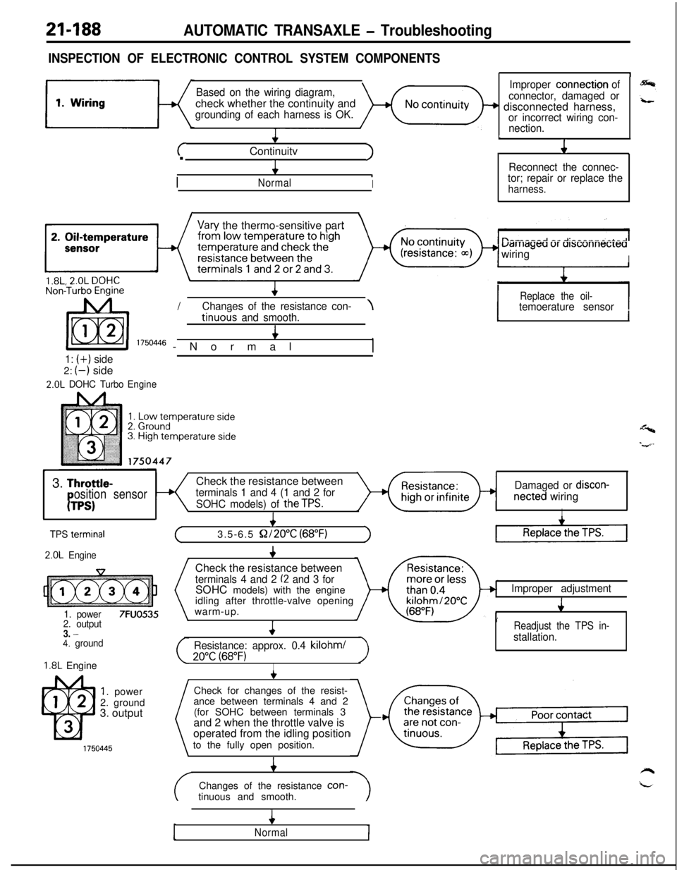
21-188AUTOMATIC TRANSAXLE - Troubleshooting
INSPECTION OF ELECTRONIC CONTROL SYSTEM COMPONENTS
Based on the wiring diagram,check whether the continuity and
grounding of each harness is OK.
+
cContinuitvJ.
4
/
.NormalI
1
Improper connection of
connector, damaged or
+ disconnected harness,or incorrect wiring con-
nection.
L
J1
Reconnect the connec-
tor; repair or replace the
harness.
I\
Vary the thermo-sensitive part
uarriageu ur ursconnecreawiring
I/
IReplace the oil-Chanaes of the resistance con-\temoerature sensortinuo& and smooth.4
I 1750446 -Normal,
1: (+) side2:
(-) side
2.0L DOHC TurboEngine
1I
Y3.
Throttle-Check the resistance betweenosition sensorterminals 1 and 4 (1 and 2 forDamaged or discon-
PTPS)SOHC models) of theTPS.netted wiringI
I
TPS termrnal
2.0L Engine
1. power
7FUO5352. output3. -4. ground
1.8L Engine
1. power
2. ground
3. output
+
(3.5-6.5 S2/2O”C (68°F)1Check the resistance between
terminals 4 and 2 (2 and 3 forSOHC models) with the engine
idling after throttle-valve opening
warm-up.
4
Resistance: approx. 0.4 kilohml
20°C (68°F)I
Improper adjustment
J
’Readjust the TPS in-
stallation.Check for changes of the resist-
ance between terminals 4 and 2
(for SOHC between terminals 3
and 2 when the throttle valve is
operated from the idling position
to the fully open position.
4Changes of the resistance con-
tinuous and smooth.
4
Normal
Page 883 of 1216
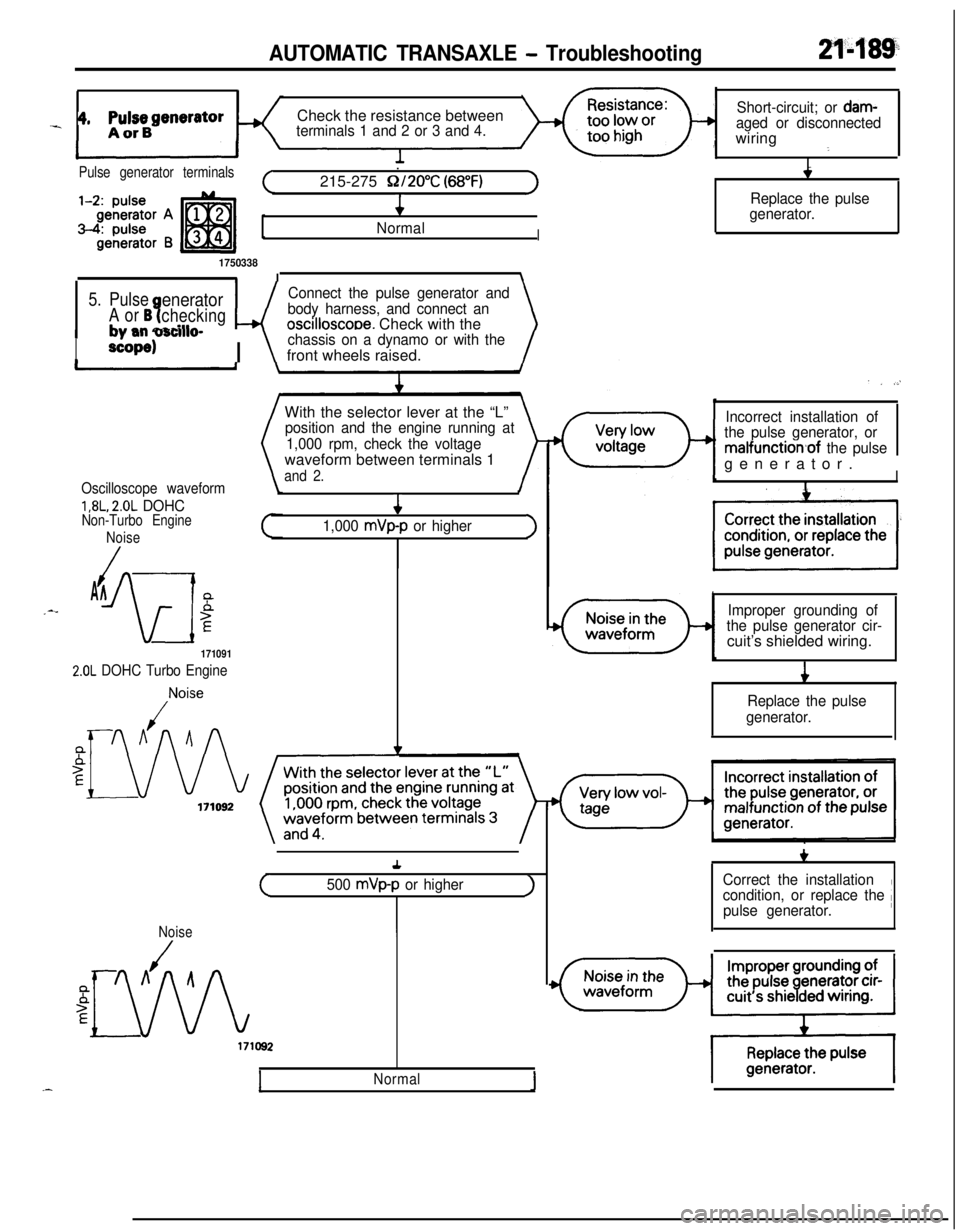
AUTOMATIC TRANSAXLE - Troubleshooting21-189
_ 4, ppBgeneratorCheck the resistance betweenterminals 1 and 2 or 3 and 4.Short-circuit; or
dam-aged or disconnectedwiring
:
I
.
4
/
NormalI
1750338II\
Pulse generator terminals.(215-275 Q/2O”C (68°F)1
5. PulseeneratorConnect the pulse generator and
A or B?checkingwbody harness, and connect an
+ mm narillroscilloscooe. Check with the\
I
#, -mm v3nlwdP
scope)I \
chassis on a dynamo or with thefront wheels raised.
With the selector lever at the “L”
position and the engine running at
1,000 rpm, check the voltagewaveform between terminals 1
and 2.
Oscilloscope waveform
1,8L, 2.0L DOHCNon-Turbo Engine
Noise
/AA_--
iw
5E4
1,000 mVp-p or higher>
171091
2.0L DOHC Turbo Engine
,Noise
Replace the pulse
generator.
. . .,’
Incorrect installation of
the pulse generator, or
malfunction,of the pulsegenerator.
II
Improper grounding of
the pulse generator cir-cuit’s shielded wiring.
i
Replace the pulse
generator.+
(500 mVp-p or higherJ
Noise
Normal1
+,I
Correct the installation
condition, or replace the /pulse generator.
Page 886 of 1216
21-192AUTOMATIC TRANSAXLE - Troubleshooting
9. Damper clutchcontrol solenoid
valve (DCCSV)
1,8L, 2.0L DOHC
Non-Turbo
Engine
Solenoid valve
connector terminals1:
PCSV2: DCCSV
3: SCSV-A4:
SCSV-B
1750338Check the resistance between
terminal 2 of the solenoid valve
connector and the transmission
case.too low or too
G’Short-circuit
0,s” dam-
aged or d&connectedwiring
.: ’
I
(Standard value: 3 Q/20%)I
INormalI*Sticking *Sticking
is isusually at the usually at the
release side. release side.
1 Replace the DCCSV. 1
171096
b adjust if necessary.
Replace the acceleratorswitch.
(No continuity (resistance: Q)))4
Normal
Page 888 of 1216
21-194AUTOMATIC TRANSAXLE - TroubleshootingCheck for continuity between the
kickdown servo switch terminal
TFA0389Start the engine, set to the “L”Continuity exists
+
range, and let the engine idle;check for continuity between the
kickdown servo switch terminaland the transaxle case.
NOTE: Be sure the brakes are
applied during this check.
+No continuity
“‘
Poor contact (sticking)
4
Replace the K/D servoswitch.
.
+
Normal
Disconnect the harness (both A
and B connectors) from the vehi-
Malfunction of the ori-
ginal TCU
Consider the original TCU to be
Same problem (as before TCU
exchange) occurs.