1991 MITSUBISHI ECLIPSE oil change
[x] Cancel search: oil changePage 660 of 1216

19-12STEERING - Service Adjustment Procedures
Pressure ofWater pump
pulleyOlA0059Fluid fluctuation
While engine
runningWhile enginestopped13uo139
Return hoseVinyl hose
x ,3Ao,42-
V-BELT TENSION CHECKNlSFliAl
1.Check to be sure that the belt is not damaged and that the
V-belt is correctly attached to the groove of the pulley.
NOTE, If there is abnormal noise or belt slippage, check the belt
tension and check for unusual wear or abrasion, or damage,
of the
pullev contact surface, and for scars or scratches onthe
pulley.2.
Press in V-belt at the illustrated position with about 100 N
(22 Ibs.) and measure deflection.
Standard value: 6-9 mm
1.26.35 in.)
3. If there is a deviation from the standard value range, make
an adjustment of the belt tension by following the procedures
described below.
(1) Loosen bolts A, B and C (for holding the oil pump).
(2) Place a bar or similar object against the body of the oil
pump, and, while manually providing the suitable
amount of tension, adjust the amount of
flexion of the
belt.
(3) Tighten bolts A, B and C (for holding the oil pump).
(4) Check the amount of flexion of the belt; readjust if
necessary.
CautionThe check should be made after turning the engine
one time or more in the regular direction of rotation (tothe
dght).
FLUID LEVEL CHECKNlSFIAI
1.Park the vehicle on a flat, level surface, startthe engine, andthen turn the steering wheel several times to raise the
temperature of the fluid to approximately
50-60°C
(122-140°F).2. With the engine running, turn the wheel all the way to the
left and right several times.3. Check the fluid in the oil reservoir for foaming or milkiness.
Check the difference of the fluid level when the engine is
stopped, and while it is running. If the fluid level changes
considerably, air bleeding should be done.
FLUID REPLACEMENTNlSFJAJ
1.Raise the front wheels on a jack, and then support them with
rigid racks.2. Disconnect the return hose connection.
3.Connect a vinyl hose to the return hose, and drain the oil into
a container.
Page 661 of 1216

STEERING - Service -Adjustment Procedures < Power Steering >IgJf~
4.Disconnect the high-tension cable, and then while operating
the starting motor intermittently, turn the steering wheel all;
the way to the left and right several times to drain all of the
fluid.
Caution, 35
Be careful not to position thq high-tension able ye&r the
carburetor or the delivery pipe.5. Connect the return hoses securely, and then
secur& it ,with
the clip.6. Fill the oil reservoir with the specified fluid up
td the Ibwerposition of the filter, and then bleed the air.
.’
Specified fluid:MOPAR ATF PLUS (Automatic Transmis-sion Fluid Type 7176)/Automatic trans-
mission fluid “DEXRON” or “DEXRON II”Fluid level change:
within
5 mm (2 in.)While engineWhile engine
runningstoppedl?lrnl?J3
BLEEDINGNlSFKAG
1.Jack up the front wheels and support them by using a floor
stand.2. Manually turn the oil pump pulley a few times.
3. Turn the steering wheel all the way to the left and right
several times.
4.Disconnect the high-tension cable, and then, while operatingthe starting motor intermittently, turn the steering wheel all
the way to the left and right several times
(for 1-5 to 20
seconds).
Caution
1. During air bleeding, replenish the fluid supply so thatthe level never falls below the lower positiin
@f the
eiter.I .“:
2. If air bleeding is done while engine is runnind, ‘the air
will be
brokeir up and absorbed intti the fluid;‘?ti’ sureto do the bleeding only while cranking.
5.Connect the ignition cable, and then start the engine (idling).6. Turn the steering wheel to the left and right until there are
no air bubbles in the oil reservoir.
7. Confirm that the fluid is not milky, and that the level is
upito the specified position on the level gauge.
8.Confirm that there is very little change in the fluid level whenthe steering wheel is turned left and right.
9.Check whether or not the change in the fluid level is within5 mm
(.2 in.) when the engine is stopped and when it is
running.
Caution
1.If the change of the fluid level is 5 mm I.2 in.) or more,
the air has not been completely bled from the system,
and thus must be bled completely.2. If the fluid level rises suddenly after the engine is
stopped, the air has not been completely bled.
3. If air bleeding is not complete, there will be abnormal
noises from the pump and the flow-control valve, and
this
condition could cause a lessening of the life of the
pump, etc.
Page 882 of 1216

21-188AUTOMATIC TRANSAXLE - Troubleshooting
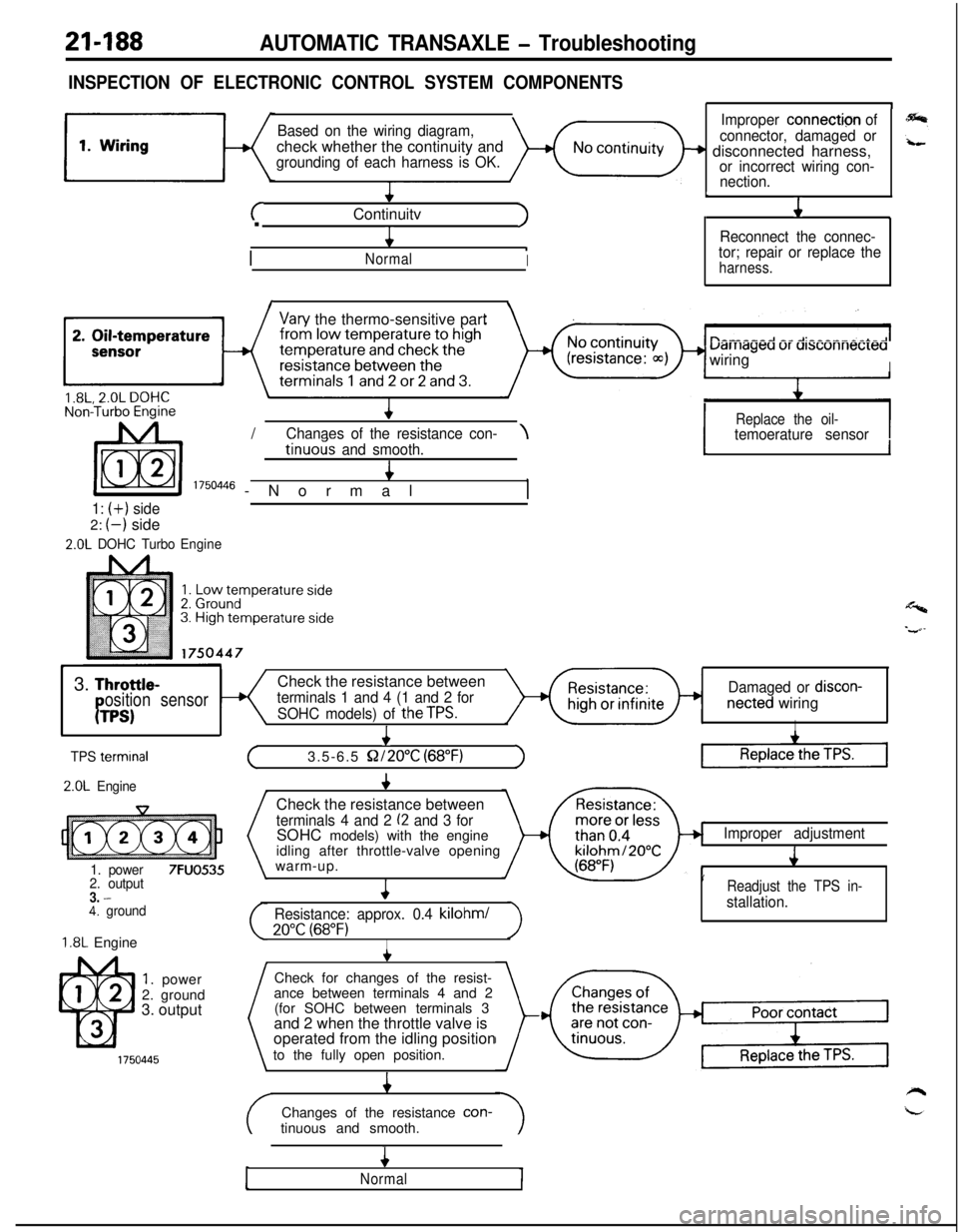
INSPECTION OF ELECTRONIC CONTROL SYSTEM COMPONENTS
Based on the wiring diagram,check whether the continuity and
grounding of each harness is OK.
+
cContinuitvJ.
4
/
.NormalI
1
Improper connection of
connector, damaged or
+ disconnected harness,or incorrect wiring con-
nection.
L
J1
Reconnect the connec-
tor; repair or replace the
harness.
I\
Vary the thermo-sensitive part
uarriageu ur ursconnecreawiring
I/
IReplace the oil-Chanaes of the resistance con-\temoerature sensortinuo& and smooth.4
I 1750446 -Normal,
1: (+) side2:
(-) side
2.0L DOHC TurboEngine
1I
Y3.
Throttle-Check the resistance betweenosition sensorterminals 1 and 4 (1 and 2 forDamaged or discon-
PTPS)SOHC models) of theTPS.netted wiringI
I
TPS termrnal
2.0L Engine
1. power
7FUO5352. output3. -4. ground
1.8L Engine
1. power
2. ground
3. output
+
(3.5-6.5 S2/2O”C (68°F)1Check the resistance between
terminals 4 and 2 (2 and 3 forSOHC models) with the engine
idling after throttle-valve opening
warm-up.
4
Resistance: approx. 0.4 kilohml
20°C (68°F)I
Improper adjustment
J
’Readjust the TPS in-
stallation.Check for changes of the resist-
ance between terminals 4 and 2
(for SOHC between terminals 3
and 2 when the throttle valve is
operated from the idling position
to the fully open position.
4Changes of the resistance con-
tinuous and smooth.
4
Normal
Page 891 of 1216

AUTOMATIC TRANSAXLE - TroubleshootingRemedial Steps If Oil Pressure Is Not Normal
F4A22.,,‘
frouble symptomProbable causeRemedy1;
I. *Line pressures
a.Clogging of oil filtera.Visually inspect the oil filter; replace the oil filte
are all low (or high).
if it is clogged.
NOTEb.Improper adjustment of oil press-b.Measure line pressure @ (kickdown brake*“Line pressures”ure (line pressure) of regulator
pressure); if the pressure is not the standard
refers to oil
ress-ures@,@, 4 and
8
valvevalue, readjust the line pressure, or, if neces-sary, replace the valve body assembly.
@in the “Standardc.Sticking of regulator valvec.Check the operation of the regulator valve;oil pressure table”repair if necessary, or replace the valve body
on the previousassembly.
page.d.Looseness of valve body tighten-d.Tighten the valve body tightening bolt and
ing partinstallation bolt.‘- ,
e.Improper oil pump dischangee.Check the side clearance of the oil pump gehr;
pressurereplace the oil pump assembly if necessary.
I. Improper reducinga.Improper line pressurea.Check the @ kickdown brake pressure (line
pressurepressure); if the line pressure is not the
standard value, check as described in item 1
above.
b.Clogging of the filter (L-shapedb.Disassemble the valve body assembly and
type) of the reducing-pressure cir-check the filter; replace the filter if it is clogged.cuit
c.Improper adjustment of the re-c.Measure the @I reducing pressure; if it is not
ducing pressurethe standard value, readjust, or replace the
valve body assembly.
d.Sticking of the reducing valved.Check the operation of the reducing valve; if
necessary, repair it, or replace the valve body
assembly.
e.Looseness of valve body tighten-e.Tighten the valve body tightening bolt and
ing partinstallation bolt.
#. Improper kick-a.Malfunction of the D-ring or seala. Disassemble the kickdown servo and check
down brake press-ring of the sleeve or kickdownwhether the seal ring or D-ring is damaged.
ureservo piston.If it is cut or has scratches, replace the seal ring
or D-ring.
b.Looseness of valve body tighten-b.Tighten the valve body tightening bolt and
ing partinstallation bolt.
c.Functional malfunction of thec.Replace the valve body assembly.
valve body assembly
. Improper front
clutch pressure
a.Malfunction of the D-ring or seala. Disassemble the kickdown servo and check
ring of the sleeve or kickdownwhether the seal ring or-D-ring is damaged.servo piston.
If it is cut or has scratches, replace the seal ring
or D-ring.
b.Looseness of valve body tighten-b.Tighten the valve body tightening bolt and
ing partinstallation bolt.c.Functional malfunction of thec.Replace the valve body assembly.
valve body assembly
d.Wear of the front clutch piston ord.Disassemble the transaxle itself and check
retainer, or malfunction of the
@whether or not there is wear of the front clutch
D-ring, @ seal, ring.piston and retainer inner circumference, or
ra;;; to the figure on the nextdamage of the D-ring. If there is any wear or
damage, replace the piston, retainer, D-ring
and/or seal ring.
1. Improper endclutch pressure
a.Malfunction of a D-ring @or seala.Disassemble the end clutch and check the sealring 0, @of the end clutch or
O-ring @I of the pipe (Refer to thering, D-ring of the piston, seal ring of thefollowing figure.)retainer, etc.; replace if there are cuts, scars,
scratches or damage.
b.Looseness of valve body tighten-b.Tighten the valve body tightening bolt and
ing partinstallation bolt.c.Functional malfunction of thec.Replace the valve body assembly.
valve body assembly
Page 893 of 1216

AUTOMATIC TRANSAXLE - Troubleshooting
F4A33-W4A33Trouble symptom
1. Line pressures areall low (or high).
NOTE* “Line pressures”
refers to oil
pressure @,@I, 0,0, @I and 0, inthe “Standard oil
pressure table” on
the previous page.
2. Improper reducing
pressure3. Improper
kickdown brake
pressure (Apply)
4. Improper
kickdown brake
pressure (Release)
5. Improper front
clutch pressureProbable cause
a.Clogging of oil filter
b.Improper adjustment of oil
pressure (line pressure of
regulator valve
c.Functional malfunction of valve
body assembly
d.Looseness of valve bodytightening part
e.Improper oil pump dischange
pressure
a.Clogging of the filter (L-shaped
type) of the reducing-pressurecircuit
b.Improper adjustment of oil
pressure
c.Functional malfunction of thevalve body assembly
a.Malfunction of the seal ring @,
D-ring @I or seal ring 0 of thesleeve of the kickdown servo
piston.
b.Functional malfunction of the
valve body assembly
a.Malfunction of the seal ring @,
D-ring @ or seal ring a> of thesleeve of the kickdown servo
piston.
b.Functional malfunctio? of the
valve body assembly
a.Malfunction of the seal ring @,
D-ring @or seal ring Q3 of thesleeve of the kickdown servo
piston.
b.Functional malfunction of the
valve body assembly
c.Wear of the front clutch piston or
retainer, or malfunction of theD-ring 0 or seal ring @.
Remedy
a.Visually inspect the oil filter; replace the oil filter
if it is clogged.
b.Measure line pressure @ (kickdown brake
pressure); if the pressure is not the standard
value, readjust the line pressure, or, if
necessary, replace the valve body assembly.
c.Replace the valve body assembly.
d.Tighten the valve body tightening bolt and
installation bolt.
e.Check the side clearance of the oil pump gear;
replace the oil pump assembly if necessary.
a.Disassemble the valve body assembly and
check the filter; replace the filter if it is clogged.
b.Measure the @ reducing pressure; if it is notthe standard value, readjust, or replace the
valve body assembly.
2.Replace the valve body assembly.
a.Disassemble the kickdown servo and check
whether the seal ring or D-ring is damaged.
If it is cut or has scratches, replace the seal ring
or D-ring.
3.Replace the valve body assembly.
3.Disassemble the kickdown servo and check
whether the seal ring or D-ring is damaged.
If it is cut or has scratches, replace the seal ring
or D-ring.
3.Replace the valve body assembly.
3.Disassemble the kickdown servo and checkwhether the seal ring or D-ring is damaged.
If it is cut or has scratches, replace the seal ring
or D-ring.
I.
Replace the valve body assembly.
:.Disassemble the transaxle itself and checkwhether or not there is wear of the front clutch
piston and retainer inner circumference, or
damage of the D-ring and/or seal ring. If there is
any wear or damage, replace the piston,
retainer, D-ring and/or seal ring.
Page 908 of 1216

21-214AUTOMATIC TRANSAXLE - Service Adjustment Procedures
'50157
F4
1
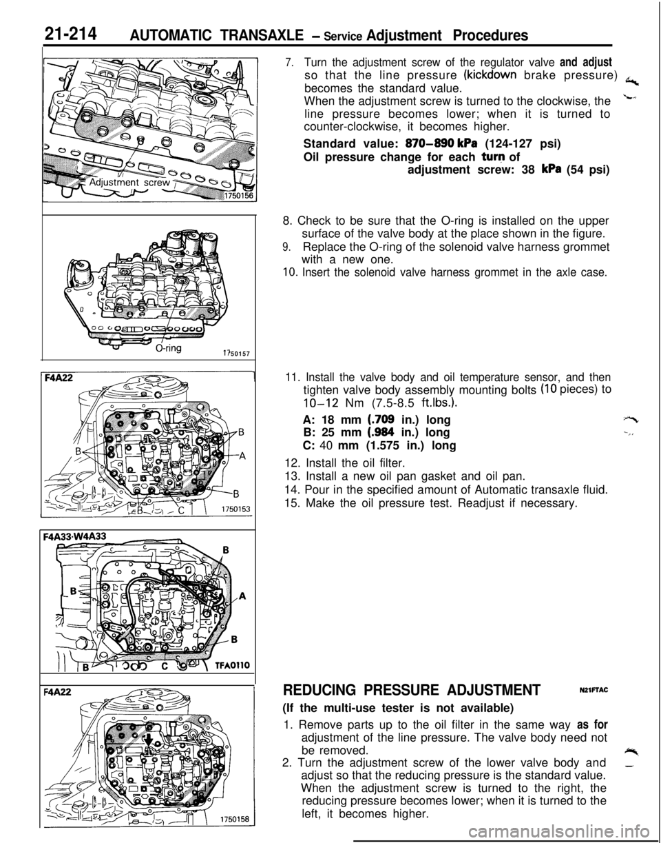
7.Turn the adjustment screw of the regulator valve and adjustso that the line pressure
(kickdown brake pressure) a,becomes the standard value.
When the adjustment screw is turned to the clockwise, the
Lline pressure becomes lower; when it is turned to
counter-clockwise, it becomes higher.
Standard value:
870-890 kPa (124-127 psi)
Oil pressure change for each turq of
adjustment screw: 38
kPa (54 psi)
8. Check to be sure that the O-ring is installed on the upper
surface of the valve body at the place shown in the figure.
9.Replace the O-ring of the solenoid valve harness grommet
with a new one.
10. Insert the solenoid valve harness grommet in the axle case.
11. Install the valve body and oil temperature sensor, and then
(IO pieces) to
tighten valve body assembly mounting bolts
IO-12 Nm (7.5-8.5 ft.lbs.).A: 18 mm
(.709 in.) long
B: 25 mm
(.984 in.) long
C: 40 mm (1.575 in.) long
12. Install the oil filter.
13. Install a new oil pan gasket and oil pan.
14. Pour in the specified amount of Automatic transaxle fluid.
15. Make the oil pressure test. Readjust if necessary.
+-t
--,,
REDUCING PRESSURE ADJUSTMENTNZlFTAC(If the multi-use tester is not available)
1. Remove parts up to the oil filter in the same way as for
adjustment of the line pressure. The valve body need not
be removed.
+%2. Turn the adjustment screw of the lower valve body and_adjust so that the reducing pressure is the standard value.
When the adjustment screw is turned to the right, the
reducing pressure becomes lower; when it is turned to the
left, it becomes higher.
Page 909 of 1216

AUTOMATIC TRANSAXLE - Service Adjustment Piocedures21-215
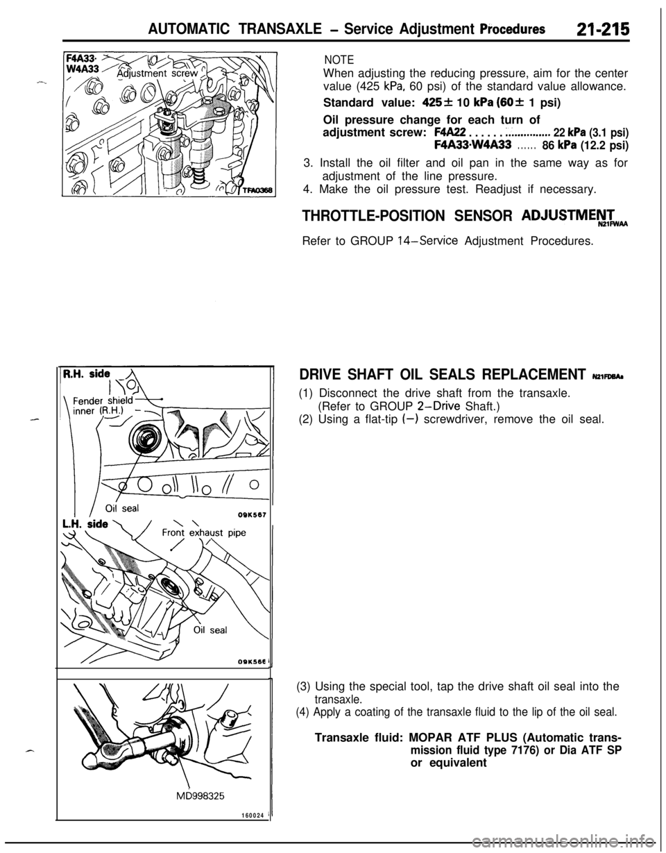
NOTEWhen adjusting the reducing pressure, aim for the center
value (425
kPa, 60 psi) of the standard value allowance.
Standard value:
425+ 10 kPa (60+ 1 psi)
Oil pressure change for each turn of
adjustment screw:
F4A22 . . . . . . ;...........,.. 22 kPa (3.1 psi)
F4A33mW4A33. . . . . .86 kPa (12.2 psi)3. Install the oil filter and oil pan in the same way as for
adjustment of the line pressure.
4. Make the oil pressure test. Readjust if necessary.
OQK567
OSKS68
Mb998325
160024
THROTTLE-POSITION SENSOR ADJUSTMEN&
Refer to GROUP
14-Service Adjustment Procedures.
DRIVE SHAFT OIL SEALS REPLACEMENT NZWWA,(1) Disconnect the drive shaft from the transaxle.
(Refer to GROUP
2-Drive Shaft.)
(2) Using a flat-tip
(-) screwdriver, remove the oil seal.
(3) Using the special tool, tap the drive shaft oil seal into the
transaxle.
(4) Apply a coating of the transaxle fluid to the lip of the oil seal.Transaxle fluid: MOPAR ATF PLUS (Automatic trans-
mission fluid type 7176) or Dia ATF SPor equivalent
Page 924 of 1216

-2.rt-2-30~~ AUTOMATIC TRANSAXLE - Transaxle Assembly
;haft1770083
DISASSEMBLYNZlLEAl1. Clean away any sand, mud, etc. adhered around the
.+
transaxle..
2.
Place the transaxle assembly on the workbench with the oil--’
pan down.
3. Remove the torque converter.
4. Measuring input shaft end play before disassembly will
usually indicate when a thrust washer change is required
(except when major parts are replaced). Thrust washers arelocated between reaction shaft support and rear clutch
retainer, and between reaction shaft support and front
clutch retainer.
Mount a dial indicator to converter housing with the Dial
Indicator Support. Make sure that the indicator plunger is
seated against end of input shaft.
When checking end play, pull out or push in the input shaft
with pliers. Be careful not to scratch the input shaft. Record
indicator reading for reference when reassembling transax-
le.5. Remove the pulse generator “A” and “B”
6. Remove manual control lever, then remove inhibitor
switch.
7. Remove snap ring then remove
kickdown servo switch.