1991 MITSUBISHI ECLIPSE height
[x] Cancel search: heightPage 181 of 1216

BRAKES - Service Adjustment Procedures5-47switch
switch
v14F516
Idown ,./
F14517
F14518
F14519
SERVICE ADJUSTMENT PROCEDURES
BRAKE PEDAL INSPECTION AND ADJUSTM&g
1.Measure the brake pedal height as illustrated. If the brake
pedal height is not within the standard value, adjust as
follows.
Standard value (A): 176181 mm (6.9-7.1 in.)(1) Disconnect the stop light switch connector, loosen the
lock nut, and move the stop light switch to a position
where it does not contact the brake pedal arm.
(2) Adjust the brake pedal height by turning the operating
rod with pliers (with the operating rod lock nut
loosened), until the correct brake pedal height is
obtained.(3) After screwing in the stop light switch until it contacts
the brake pedal stopper (just before the brake pedal is
caused to move), return the stop light switch
l/2 to 1turn and secure by tightening the lock nut.
(4) Connect the connector of the stop light switch.
(5) Check to be sure that the stop light is not illuminated
with the brake pedal unpressed.
Reference value (B): 0.5-1.0 mm
(.02-M in.)
2. With the engine stopped, depress the brake pedal two or
three times. After eliminating the vacuum in the power
brake booster, press the pedal down by hand, and confirmthat the amount of movement before resistance is met
(the free play) is within the standard value range.
Standard value
(C): 3-8 mm (.l-.3 in.)
If the free play is less than the standard value, confirm thatthe clearance between the stop light switch and brake
pedal is within the standard value.
If the free play exceeds the standard value, it is probably
due to excessive play between the
clevis pin and brake
pedal arm. Check for excessive clearance and replace
faulty parts as required.
3. Start the engine, depress the brake pedal with approxi-
mately 500 N (110 Ibs.) of force, and measure the clearancebetween the brake pedal and the floorboard.
Standard value (D): 80 mm (3.1 in.) or moreIf the clearance is less than the standard value, check for
air trapped in the brake line and for brake fluid leaks. If
necessary, check the brake system mechanism (excessiveshoe clearance due to faulty auto adjuster) and repair
faulty parts as required.
Page 183 of 1216

BRAKES - Service Adjustment Procedures5-43When engine is
stoppedNo good
0
wtwo061
VV;Videngine is
t4uoo60
Caution
If the number of brake lever notches engaged is less
than the standard value, the cable has been pulledexcessively, and failure of the automatic adjuster
mechanism will result. Be sure tti adjust it to within the
standard value.(6) After making the adjustment, check to be sure that there is
no play between the adjusting nut and the pin. Also check
to be sure that the adjusting nut is securely held at the nut
holder.(7) After adjusting the lever stroke, jack up the rear of the
vehicle.(8) With the parking brake lever in the released position, turn
the rear wheel to confirm that the rear brakes are not
dragging.
PARKING BRAKE SWITCH CHECKN05FDAB
(1) Disconnect the connector of the parking brake switch, and
connect an ohmmeter to the parking brake switch and the
switch installation bolt.
(2) The parking brake switch is good if there is continuity whenthe parking brake lever is pulled and there is no continuity
when it is returned.
BRAKE BOOSTER OPERATING
lNSPECTIONNoSFcuFor simple checking of brake booster operation, carry out the
following tests.
(1) Run the engine for one or two minutes, and then stop it.
(2) Step on the brake pedal several times with normal
pressure.If the pedal depressed fully the first time. but gradually
becomes higher when depressed succeeding times, the
booster is operating properly.
If the pedal height remains unchanged, the booster is
faulty.(3) With the engine stopped, step on the brake pedal several
times with the same pressure to make sure that the pedal
height will not change.
Then step on the brake pedal and start the engine.
If the pedal moves downward slightly, the booster is in
good condition. If there is no change, the booster is faulty.
(4) With the engine running, step on the brake pedal and then
stop the engine.
Hold the pedal depressed for 30 seconds. If the pedal
height does not change, the booster is in good condition.
If the pedal rises, the booster is faulty.
If the above three tests are okay, the booster performance canbe determined as good.
If one of the above three tests is not okay at last, the check
valve, vacuum hose, or booster will be faulty.
Page 232 of 1216

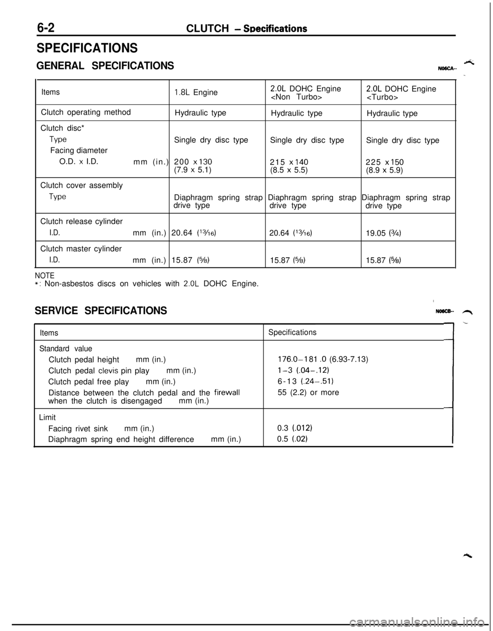
6-2CLUTCH - SDecifications
SPECIFICATIONS
GENERAL SPECIFICATIONS
Items1.8L Engine2.0L DOHC Engine
Clutch operating method
Hydraulic type
Hydraulic type
Hydraulic type
Clutch disc*
TypeSingle dry disc type
Single dry disc type
Single dry disc type
Facing diameter
O.D.
x I.D.
mm (in.) 200 x 130215 x 140225 x 150(7.9 x 5.1)
(8.5 x 5.5)
(8.9 x 5.9)
Clutch cover assembly
TypeDiaphragm spring strap Diaphragm spring strap Diaphragm spring strap
drive type
drive type
drive type
Clutch release cylinder
I.D.mm (in.) 20.64 (13/16)20.64 (13/6)19.05 (3h)Clutch master cylinder
I.D.mm (in.) 15.87 (%)15.87 (%)15.87 (543)
NOTE*: Non-asbestos discs on vehicles with 2.0L DOHC Engine.
SERVICE SPECIFICATIONS
Items
Standard valueClutch pedal heightmm (in.)
Clutch pedal
clevis pin playmm (in.)
Clutch pedal free playmm (in.)
Distance between the clutch pedal and the firewall
when the clutch is disengagedmm (in.)
Limit
Facing rivet sinkmm (in.)
Diaphragm spring end height differencemm (in.)
NO6lX- .H,
Specifications
176.0-I 81 .O (6.93-7.13)
l-3 (.04-.12)6-13 (.24-.51)
55 (2.2) or more
0.3 (012)
0.5
(.02)L-
Page 234 of 1216

6-4CLUTCH - Troubleshooting
TROUBLESHOOTINGNO6hi.J
SymptomProbable causeRemedy
Clutch slipsInsufficient clutch pedal playAdjust
Excessive wear of clutch disc facingReplace
Hardening of clutch disc facing, or adhesion of oilReplace
Clutch release fork catchingRepair or replace parts
Weak or damaged diaphragm spring
Replace
Clogging of hydraulic systemRepair or replace parts
Gear shift malfunctionExcessive clutch pedal playAdjust
Distorted clutch disc, excessive oscillation
Replace
Clutch cover assembly wornReplace
Clutch disc spline worn or corrodedReplace
Clutch disc facing peelingReplace
Clutch release bearing wornReplace
Damaged pressure plate or flywheelReplace
Leakage, air introduction or clogging of hydraulic systemRepair or replace parts
Clutch noiseInsufficient clutch pedal playAdjust
Improper installation of clutch cover assemblyRepair or replace parts
Excessive wear of clutch disc facing
Replace
Clutch release fork catchingRepair or replace parts
Clutch release bearing worn
Replace
Weak or damaged torsion springReplace
Damaged pilot bushingReplace
Insufficient lubrication of bearing sleeve sliding surfaceRepairClutch pedal feels “heavy”
Insufficient lubrication of clutch pedalRepairInsufficient lubrication of clutch disc spline
Repair
Clutch release fork catchingRepair or replace parts
Insufficient lubrication of bearing sleeve sliding surface
Repair
Clutch chattersWorn or damaged clutch disc facingReplace
Oil adhered to clutch disc facingReplace
Uneven height of diaphragm springRepair or replace parts
Weak or damaged torsion spring
Replace
Damaged pressure plate or flywheelReplace
Loose or damaged mountingReplace or tighten
mounting
Page 235 of 1216

CLUTCH - Service Adjustment Procedures6-5Clutch pedal height
b
AClutch pedal clevis
pin play
08YO43Vehicles without
auto-cruise control
systemVehicles with
auto-cruise control
08A0025I
Clutch pedal free pIa\
08YO43
Distance between the
clutch pedal and thefirewall
when theclutch is disengaged
SERVICE ADJUSTMENT PROCEDURES
CLUTCH PEDAL INSPECTION AND ADJUSTMY’,
1.Measure the clutch pedal height (from the face of the pedalpad to the
firewall) and the clutch pedal clevis pin play
(measured at the face of the pedal pad.)
Standard value (A): 176.0-181.0 mm (6.93-7.13 in.)
Standard value (B): l-3 mm (.04-.12 in.)
2.If either the clutch pedal height or the clutch pedal clevis
pin play are not within the standard value range, adjust as
follows
:(1) For vehicles without auto-cruise control system, turn
and adjust the bolt so that the pedal height is the
standard value, and then secure by tightening the lock
nut.Vehicles with auto-cruise control system, disconnect
the clutch switch connector and turn the switch for
standard clutch pedal height. Then lock with the lock
nut.
NOTE
When the pedal height is lower than the standard value,
loosen the bolt or clutch switch, and then turn the pushrod to make the adjustment. After making the adjust-
ment, tighten the bolt or clutch switch to reach the
pedal stopper, and then lock with the lock nut.
(2) Turn the push rod to adjust the clutch pedal clevis pin
play to agree with the standard value and then secure
the push rod with the lock nut.
CautionWhen adjusting the
pedal height or the clutch pedal
clevis pin play, be careful not to push the push rodtoward the master
cylinder.3. Check to be sure that the interlock switch is as shown in
the illustration when the clutch pedal is depressed its full
stroke
[151 mm (6.0 in.)]. If necessary, loosen the lock nut
and adjust.
4.After completing the adjustments, confirm that the clutch
pedal free play (measured at the face of the pedal pad)
and the distance between the clutch pedal (the face of the
pedal pad) and the
firewall when the clutch is disengaged
are within the standard value ranges.
Standard value (C):6-13 mm (.24-.51 in.)
Standard value (D):55 mm (2.2 in.) or more
Page 247 of 1216

CLUTCH - Clutch Cover and Disc647
08A0038
6CLOO3SERVICE POINTS OF REMOVAL
NO6OSAH
1. REMOVAL OF CLUTCH COVER ASSEMBLY/P.
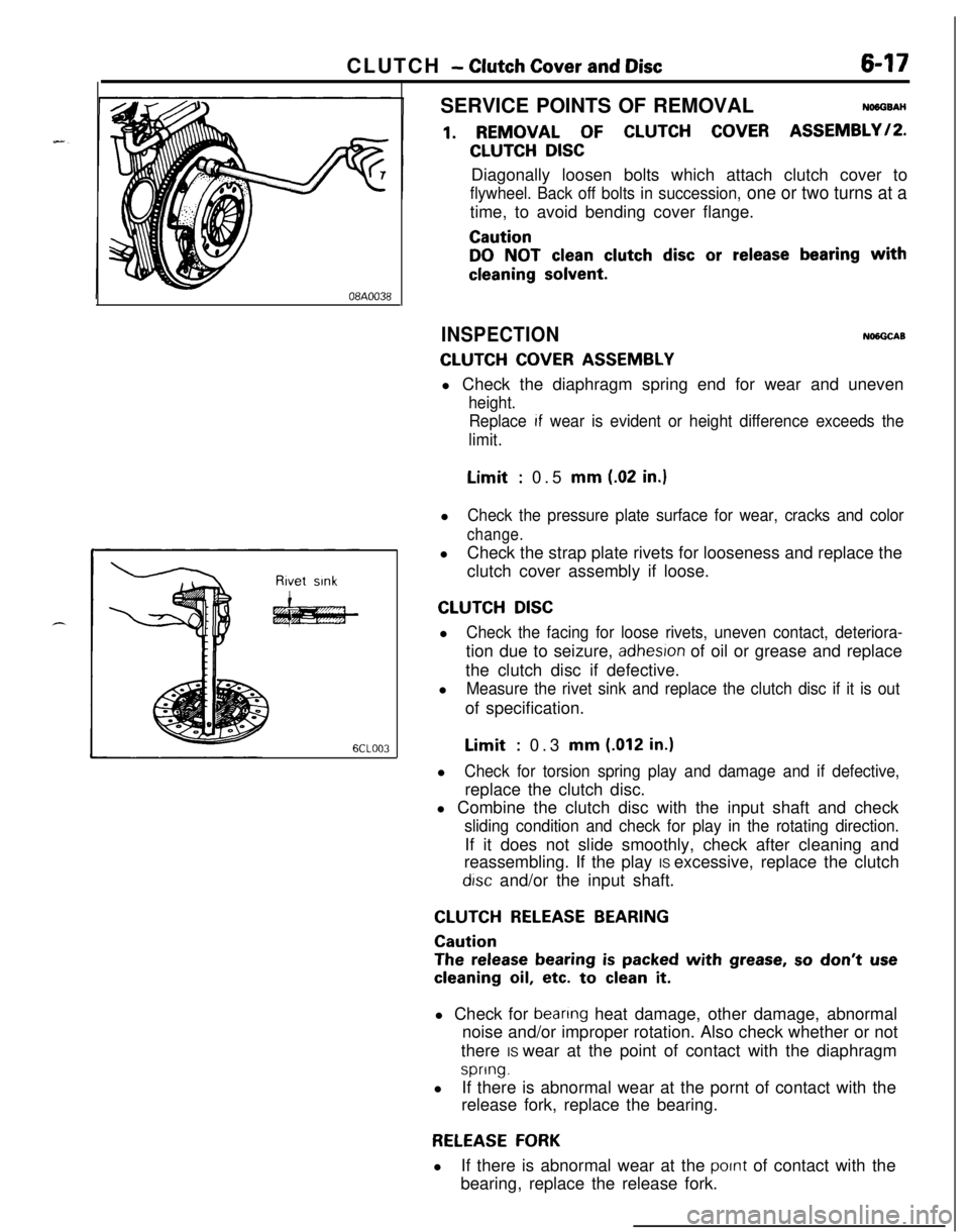
CLUTCH DISCDiagonally loosen bolts which attach clutch cover to
flywheel. Back off bolts in succession, one or two turns at atime, to avoid bending cover flange.
Caution
DO NOT clean clutch disc or release bearing with
cleaning solvent.
INSPECTIONNlNGCAB
CLUTCH COVER ASSEMBLYl Check the diaphragm spring end for wear and uneven
height.
Replace
If wear is evident or height difference exceeds the
limit.Limit
: 0.5 mm (.02 in.)l
Check the pressure plate surface for wear, cracks and color
change.lCheck the strap plate rivets for looseness and replace the
clutch cover assembly if loose.
CLUTCH DISCl
Check the facing for loose rivets, uneven contact, deteriora-tion due to seizure,
adhesron of oil or grease and replace
the clutch disc if defective.
l
Measure the rivet sink and replace the clutch disc if it is outof specification.Limit
: 0.3 mm (.012 in.)l
Check for torsion spring play and damage and if defective,replace the clutch disc.
l Combine the clutch disc with the input shaft and check
sliding condition and check for play in the rotating direction.If it does not slide smoothly, check after cleaning and
reassembling. If the play IS excessive, replace the clutch
drsc and/or the input shaft.
CLUTCH RELEASE BEARING
Caution
The release bearing is packed with grease, so don’t use
cleaning oil, etc. to clean it.l Check for
beanng heat damage, other damage, abnormal
noise and/or improper rotation. Also check whether or not
there IS wear at the point of contact with the diaphragm
spring.lIf there is abnormal wear at the pornt of contact with the
release fork, replace the bearing.
RELEASE FORKlIf there is abnormal wear at the
pornt of contact with the
bearing, replace the release fork.
Page 264 of 1216

7-16COOLING - Thermostat
INSPECTIONy+w
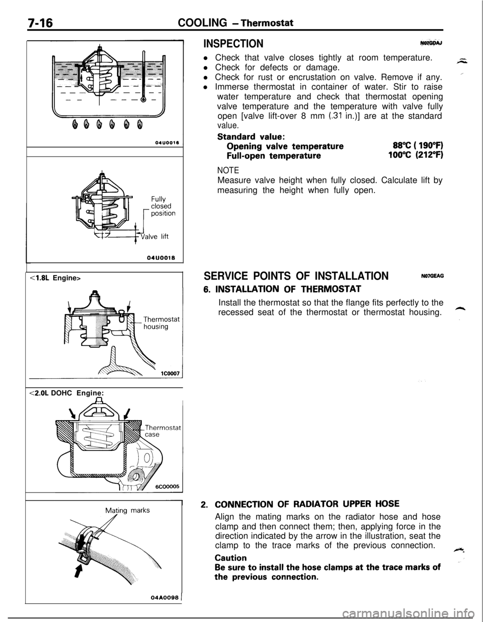
l Check that valve closes tightly at room temperature.
l Check for defects or damage.
l Check for rust or encrustation on valve. Remove if any.
l Immerse thermostat in container of water. Stir to raise
water temperature and check that thermostat opening
valve temperature and the temperature with valve fully
open [valve lift-over 8 mm
(.31 in.)] are at the standard
value.Standard
value:Opening
valve temperature
Full-open temperature
88°C ( 190°F)
100°C (212°F)
Fullyclosedpositionve lift
04UOO18<1.8L Engine><2.0L DOHCEngine:
IMating
marks
NOTEMeasure valve height when fully closed. Calculate lift by
measuring the height when fully open.
SERVICE POINTS OF INSTALLATIONNOlGEAG
6. INSTALLATION OF THERMOSTAT
Install the thermostat so that the flange fits perfectly to the
recessed seat of the thermostat or thermostat housing.
2.CONNECTION OF RADIATOR UPPER HOSEAlign the mating marks on the radiator hose and hose
clamp and then connect them; then, applying force in the
direction indicated by the arrow in the illustration, seat the
clamp to the trace marks of the previous connection.
Caution
Be sure to install the hose clamps at the trace marks ofthe
previous connection.
04A0099 )
Page 292 of 1216

9-8ENGINE - Specifications
SPECIFICATIONS
GENERAL SPECIFICATIONSBNDBCA-
Items
TypeNumber of cylinders
Boremm (in.)
Strokemm (in.)
Compression ratio
Firing order
Silent shaft
Valve timing
Intake valve
Opens (BTDC)
Closes
(ATDC)Exhaust valve
Opens (BBDC)
Closes (ATDC)
LubricationSpecifications
1.8L Engine2.0L Engine
In-line Single Over Head CamshaftIn-line Double Over Head
Camshafi44
80.6 (3.17)85 (3.35)
86 (3.39)88 (3.46)
9.09.0 (Non-Turbo)
7.8 (Turbo)
l-3-4-21-3-4-2EquippedEquipped
20”
.26” (Non-Turbo)
21’ (Turbo)
52”46” (Non-Turbo)
51’ (Turbo)
55”
55”
17”9”Pressure feed-full flow filtrationPressure feed-full flow filtration
SERVICE SPECIFICATIONSNOSCB-
-4.8L Engine>
Items
Standard Value
Engine adjustments
Engine compression pressurekPa (psi)
-Engine compression pressure difference
-between each cylinder
kPa (psi)
Intake manifold vacuum at idle
mmHg (in.Hg)510 (20)
Timing belt “B” tension
mm (in.)
5-7
(.20-.28)Cylinder head
Overall height
mm (in.)
88.5 (3.484)
Flatness of gasket surface
mm (in.)
Less than 0.05
(0019)Flatness of manifold mounting
surfacemm (in.) Less than 0.15 (.0059)Limit
Min. 920 (131)
Max. 100 (14)
-0.2
(-.008)**Limit must be -0.2
(-.008) combined
with amount of
grinding of cylinder
block gasket surface.
0.2
(008)0.3
(.012)