Page 252 of 1216
7-4COOLING - Specifications
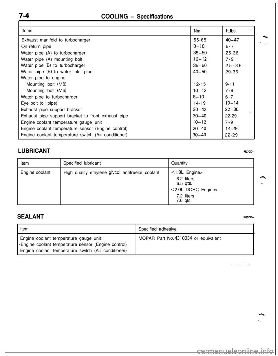
ItemsExhaust manifold to turbocharger
Oil return pipe
Water pipe (A) to turbocharger
Water pipe (A) mounting bolt
Water pipe
(B) to turbocharger
Water pipe
(B) to water inlet pipe
Water pipe to engine
Mounting bolt
(M8)Mounting bolt
(M6)Water pipe to turbocharger
Eye bolt (oil pipe)
Exhaust pipe support bracket
Exhaust pipe support bracket to front exhaust pipe
Engine coolant temperature gaugeunit
Engine coolant temperature sensor (Engine control)
Engine coolant temperature switch (Air conditioner)
Nmft.lbs. _155-65
40-47
8-106-7
35-5025-36
10-127-9
35-5025-36
40-5029-36
12-159-11
10-127-9
8-106-7
14-19
10-14
30-4222-30
30-4022-29 .’
10-127-9
20-4014-29
30-4022-29
LUBRICANT
ItemEngine coolantSpecified lubricant
High quality ethylene
glycol antifreeze coolantQuantity
6.2 liters
6.5
qts.
<2.0L DOHC Engine>
7.2 liters
7.6 qts.
SEALANTNO7CE-.
ItemEngine coolant temperature gauge unit
-Engine coolant temperature sensor (Engine control)
Engine coolant temperature switch (Air conditioner)Specified adhesive
MOPAR Part No.4318034 or equivalent
Page 253 of 1216

COOLING - Troubleshootina7-5
TRO,UBLESHOOTlNG
Symptom
OverheatProbable causeInsufficient engine coolant
Too high an anti-freeze concentrationRemedy
Replenish
Correct anti-freeze
concentration
Loose or broken drive belt
Replace
Inoperative electric cooling fan
Faulty thermosensor
Replace
Faulty electrical motorReplace
Faulty radiator fan relayReplace
Damaged or blocked (insufficiently ventilated) radiator finsCorrect
Water leaks
Damaged radiator core joint
Replace
Corroded or cracked hosesReplace
(radiator hose, heater hose, etc.)
Loose bolt or leaking gasket in water outlet fitting
(thermostat)
Loose water pump mounting bolt or leaking gasket
Faulty cap valve or setting of spring
Loose intake manifold bolts or leaking from gasket
Cracked intake manifold
Faulty automatic transaxle oil cooler operation
Blocked or collapsed hose and pipe
Loose hose and pipe connection
Faulty thermostat operation
Faulty water pump operation
Water passage clogged with slime or rust deposit or
foreign substanceCorrect or replace
Correct or replace
Replace
Retorque bolts or replace
gasket
Replace
Replace
Correct
Replace
Replace
Clean
Jo rise in temperatureFaulty thermostatReplace
Page 254 of 1216
7-6COOLING - Troubleshooting
CIRCUIT DIAGRAM
ON(IG2)SUB FUSIBLE LINK @IGNI:SWIT(: LINK@MAIN FUSIB:
0
.-----
IN
1
A-18X
1CONDENSER
A-20X ,
I!31P2
RESISTOR
(CONDENSER'
FAN MOTOR,
A-32
m
A-21
IQ
Ed3B4SB
CONDENSER$l
FAN MOTOR2
12
lal34I
A-32
0
I
I
CONDENSER FAN
MOTOR RELAYA-03X
I 2lm34
A-22
CONDENSER
t----lTH RMOBE 80R
;;aIATOR ci
ASSEMBLY'
C-72
RADIATORFANMOTOR (
A-40
II
i0
A
6
KX35-AC-U0802-NC
Page 255 of 1216
COOLING - Troubleshooting7A7
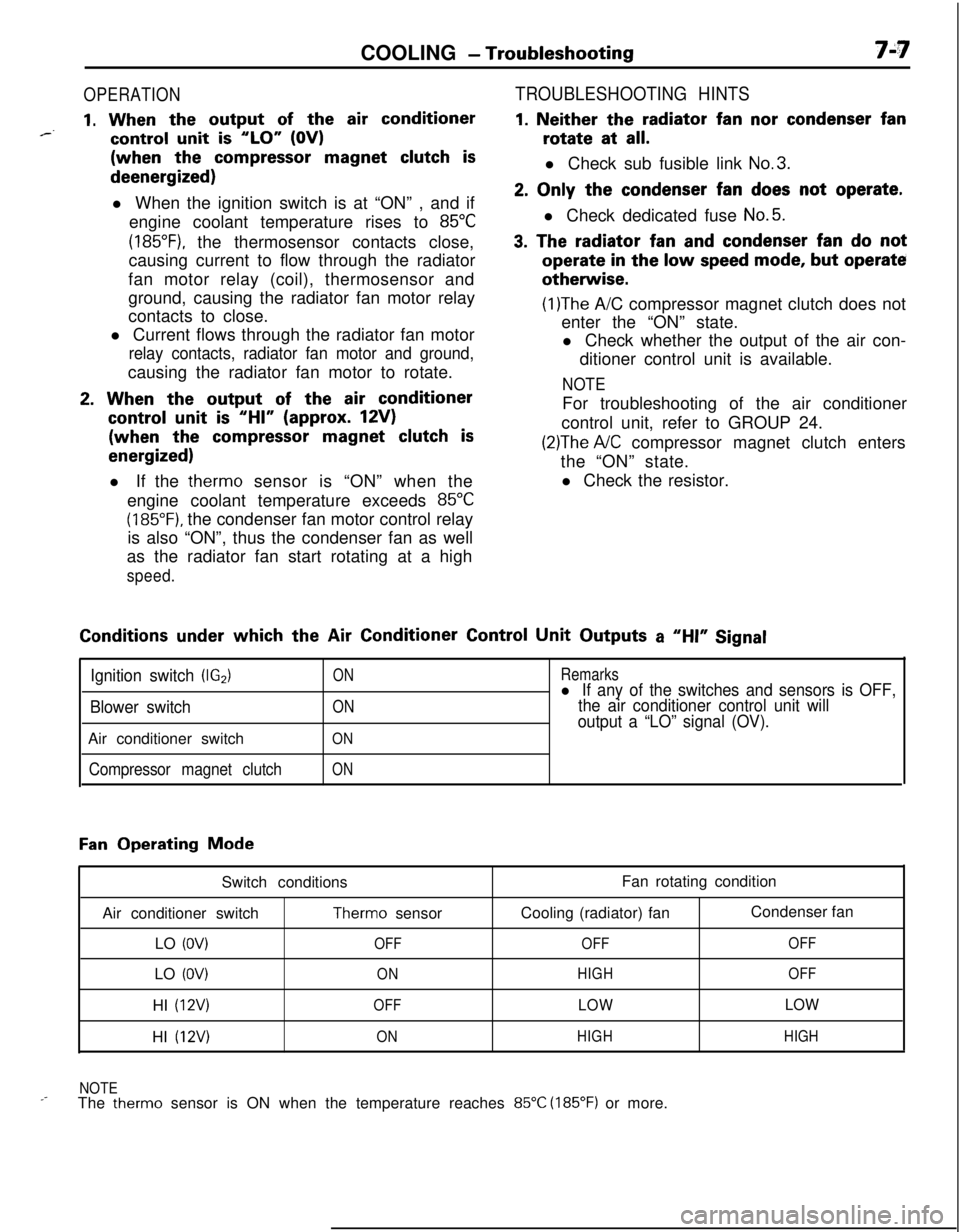
OPERATION
1. When the output of the air conditioner*--control unit is “LO” (OV)(when the
compressor magnet clutch isdeenergized)
l When the ignition switch is at “ON” , and if
engine coolant temperature rises to
85°C
(185”F), the thermosensor contacts close,
causing current to flow through the radiator
fan motor relay (coil), thermosensor and
ground, causing the radiator fan motor relay
contacts to close.
l Current flows through the radiator fan motor
relay contacts, radiator fan motor and ground,causing the radiator fan motor to rotate.
2. When the output of the air conditioner
control unit is “HI” (approx. 12V)(when the
compressor magnet clutch is
energized)l If the therm0 sensor is “ON” when the
engine coolant temperature exceeds
85°C
(185°F). the condenser fan motor control relay
is also “ON”, thus the condenser fan as well
as the radiator fan start rotating at a high
speed.
TROUBLESHOOTING HINTS
1. Neither the radiator fan nor condenser fanrotate at
all.l Check sub fusible link
No.3.
2. Only the condenser fan does not operate.l Check dedicated fuse
No.5.
3. The radiator fan and condenser fan do notoperate
in the low speed mode, but operateotherwise.
(1)The A/C compressor magnet clutch does not
enter the “ON” state.
l Check whether the output of the air con-
ditioner control unit is available.
NOTEFor troubleshooting of the air conditioner
control unit, refer to GROUP 24.
(2)The A/C compressor magnet clutch enters
the “ON” state.
l Check the resistor.Conditions
under which the Air Conditioner Control Unit Outputs a “HI” Signal
Ignition switch (IG2)
Blower switchAir conditioner switch
Compressor magnet clutch
ON
ON
ON
ON
Remarksl If any of the switches and sensors is OFF,
the air conditioner control unit will
output a “LO” signal (OV).
Fan Operating Mode
Switch conditions
Air conditioner switch
Therm0 sensor
LO
(OV)OFFLO
(OV)ONHI
(12V)OFFHI
(12V)ONFan rotating condition
Cooling (radiator) fanCondenser fan
OFFOFF
HIGHOFF
LOWLOW
HIGHHIGH
NOTE
_-The therm0 sensor is ON when the temperature reaches 85°C (185°F) or more.
Page 256 of 1216
7-8COOLING - Service Adjustment Procedures
04DooE
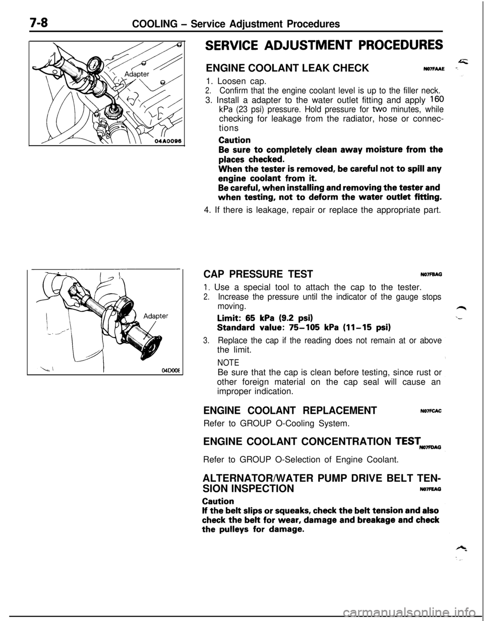
SERVICE ADJUSTMENT PROCEDURESENGINE COOLANT LEAK CHECK
NO7FAAE1. Loosen cap.
2.Confirm that the engine coolant level is up to the filler neck.3. Install a adapter to the water outlet fitting and apply
160
kPa (23 psi) pressure. Hold pressure for tvvo minutes, whilechecking for leakage from the radiator, hose or connec-
tionsCaution
Be sure to completely clean away moisture from the
places checked.When the tester
is removed, be careful not to spill anyengine coolant from
it.
Be careful, when installing and removing the tester andwhen testing, not
to deform the water outlet fitting.
4. If there is leakage, repair or replace the appropriate part.
CAP PRESSURE TESTNO’IFBAG
1. Use a special tool to attach the cap to the tester.
2.Increase the pressure until the indicator of the gauge stops
moving.Limit:
65 kPa (9.2 psi)Standard value:
75-105 kPa (11-15 psi)
3.Replace the cap if the reading does not remain at or abovethe limit.
NOTEBe sure that the cap is clean before testing, since rust or
other foreign material on the cap seal will cause an
improper indication.
ENGINE COOLANT REPLACEMENTRefer to GROUP O-Cooling System.NO’IFCACENGINE COOLANT CONCENTRATION
TESTmAGRefer to GROUP O-Selection of Engine Coolant.
ALTERNATOR/WATER PUMP DRIVE BELT TEN-
SION INSPECTION
NO7FEAGCaution
If the belt slips or squeaks, check the belt tension and also
check the belt for wear, damage and breakage and checkthe
pulleys for damage.
Page 257 of 1216
COOLING - Service Adjustment Procedures7-9Alterhatorpulley
6COOOO9
Spindle
l-
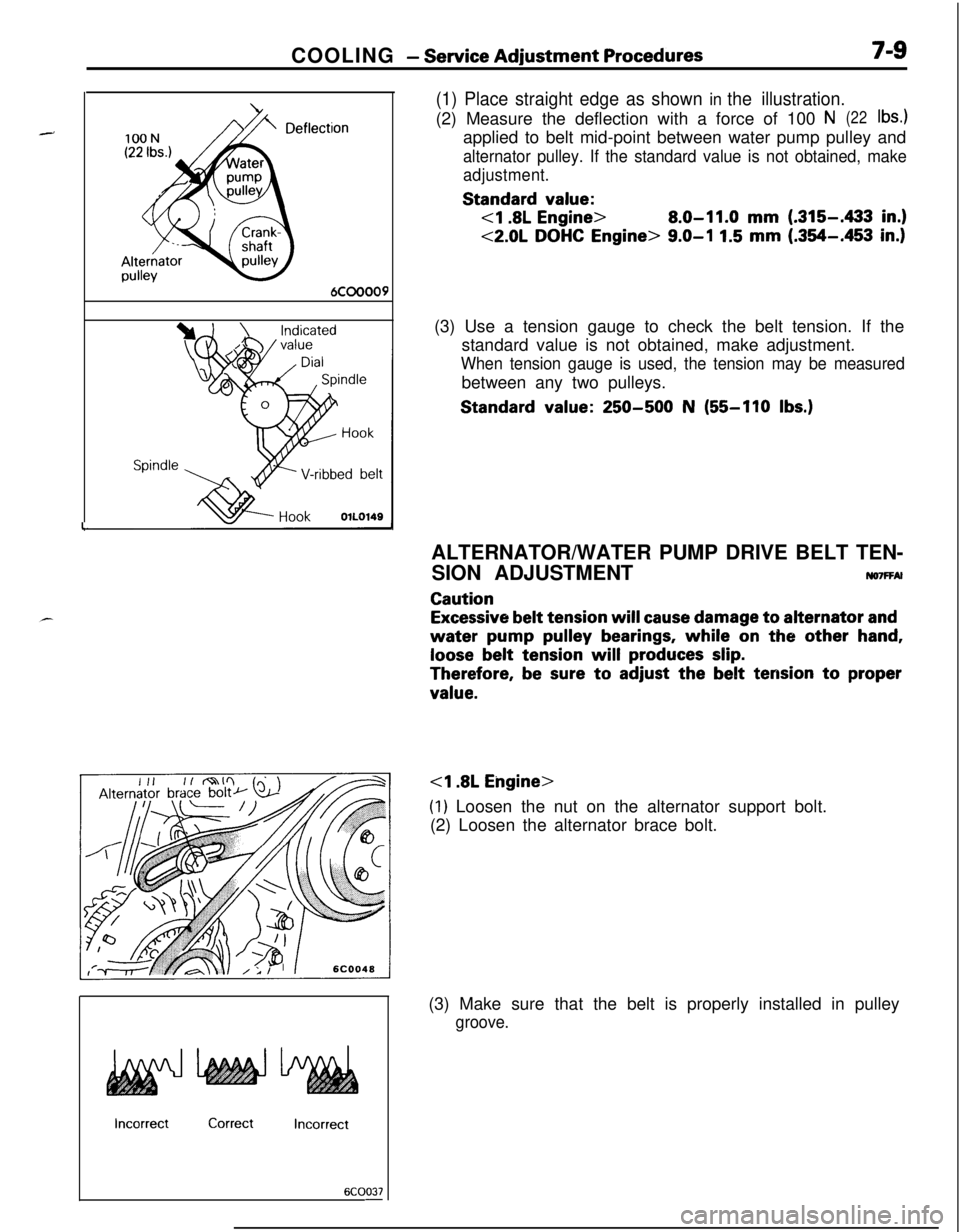
(1) Place straight edge as shown in the illustration.(2) Measure the deflection with a force of 100
N(22lb4applied to belt mid-point between water pump pulley and
alternator pulley. If the standard value is not obtained, make
adjustment.Standard
value:
8.0-11.0 mm (.315-433 in.)
<2.0L DOHC Engine> 9.0-I 1.5 mm (.354-.453 in.)(3) Use a tension gauge to check the belt tension. If the
standard value is not obtained, make adjustment.
When tension gauge is used, the tension may be measuredbetween any two pulleys.Standard
value: 250-500 N (55-110 Ibs.)
IncorrectCorrectIncorrect
6COO37-ALTERNATOR/WATER PUMP DRIVE BELT TEN-
SION ADJUSTMENT
ruo7FFAl
Caution
Excessive belt tension will cause damage to alternator and
water pump pulley bearings, while on the other hand,
loose belt tension will produces slip.
Therefore, be sure to adjust the belt tension to proper
value.
(1) Loosen the nut on the alternator support bolt.
(2) Loosen the alternator brace bolt.
(3) Make sure that the belt is properly installed in pulley
groove.
Page 258 of 1216
COOLING - Service Adjustment Procedures100N
(22 Ibs.)
DeflecAlternator
ypulley
:tion
6COOOO9
Spindle ,
HookOlLO149
IncorrectCorrectIncorrect
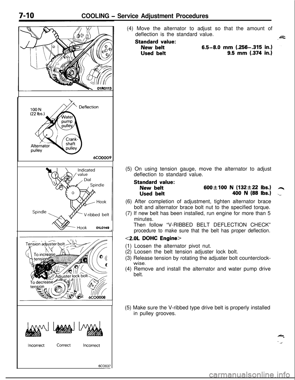
6COO37-(4) Move the alternator to adjust so that the amount of
deflection is the standard value.Standard
value:
New belt6.5-8.0 mm (.256-.315 in.)
Used belt9.5 mm (.374 in.)(5) On using tension gauge, move the alternator to adjust
deflection to standard value.Standard
value:
New belt600flOO N (132+22 Ibs.)
Used belt400 N (88 Ibs.)(6) After completion of adjustment, tighten alternator brace
bolt and alternator brace bolt nut to the specified torque.
(7) If new belt has been installed, run engine for more than 5
minutes.Then follow “V-RIBBED BELT DEFLECTION CHECK”
procedure to make sure that the belt has proper deflection.
<2.0L DOHC Engine>
(1) Loosen the alternator pivot nut.
(2) Loosen the belt tension adjuster lock bolt.
(3) Release tension by rotating the adjuster bolt counterclock-
wise.(4) Remove and install the alternator and water pump drive
belt.(5) Make sure the V-ribbed type drive belt is properly installed
in pulley grooves.
Page 259 of 1216
COOLING - Service Adjustment Procedures7-m
1(6) Adjust belt deflection by tightening adjust bolt.
:Turn adjuster bolt clockwise to increase the belt tension
and turn adjuster bolt counterclockwise to decrease the
belt tension.
Standard value:
New belt7.5-9.0 mm (.295-.354 in.)
Used belt10.0 mm (.394 in.)(7) On using tension gauge, move the alternator to adjust
deflection to standard value.
Standard value:
New belt600+100 N (132f22 Ibs.)
Used belt
400 N (88 Ibs.)(8) Tighten in order, first, adjuster lock bolt then alternator
pivot nut to the specified torque.
(9) If new belt has been installed, run engine for more than 5
minutes. Then follow “DRIVE BELT TENSION INSPEC-
TION” procedure to make sure that the belt has proper
tension and readjust if necessary.