1991 MITSUBISHI ECLIPSE check engine
[x] Cancel search: check enginePage 508 of 1216

14-54FUEL SYSTEM - Service Adjustment Procedures <2.0L Engine>
(11)Race the engine repeatedly in two or three series. Then
check that the fuel pressure does not fall when the engine
is running at idle.
(12)Check to be sure that there is fuel pressure in the return
hose also (by gently pressing the fuel return hose with a
finger while repeatedly racing the engine).
NOTEThere will be no fuel pressure in the return hose when the
volume of fuel flow is not sufficient.
(13)lf the results of the measurements made in steps (9) and
(10) above are not within the standard value, use the table
below to determine the probable cause, and then make the
necessary repair.
Condition
Fuel pressure too lowProbable causeRemedy
a. Clogged fuel filtera. Replace fuel filter.
b. Fuel leaking toward return port due tob. Replace fuel pressure regulator.
improper seating of valve in fuel pressure
regulator
c. Low delivery pressure of fuel pumpc. Replace fuel pump.
Fuel pressure too higha. Stuck valve in fuel pressure
a. Replace fuel pressure regulator.regulator
b. Clogged or bent fuel return hose or pipeb. Repair or replace hose or pipe.
Fuel pressure witha. Clogged or broken vacuum hose or nipplea. Repair or replace vacuum hose or
vacuum hose connected
nipple.
not different from fuel
pressure with vacuumb. Stuck valve in fuel pressure regulator or
b. Replace fuel pressure regulator.
hose not connecteddefective valve seating
(14)Stop the engine and check for change in fuel pressure
gauge indication, which should not drop.
If the gauge indication drops, observe the rate of drop and
determine and remove the causes according to the
following table.
Condition
Fuel pressure drops
slowly after engine is
stopped.Probable cause
Leakage from injectorRemedy
Replace injector.
Fuel pressure drops
im-Check valve in fuel pump does not closeReplace fuel pump.
mediately after engine is
stopped.
(15)Reduce the fuel pressure in the fuel line.
(16)Disconnect the high pressure fuel hose and remove the
fuel-pressure gauge from the delivery pipe.
Caution
Cover the hose connection with shop towel to prevent
splash of fuel that could be caused by residual pressurein the fuel pipe line.
(17)Mount a new O-ring in the groove at the end of the high
pressure fuel hose.
Page 509 of 1216

FUEL SYSTEM - Service Adjustment Procedures <2.0L Engine>14-55
(18)Connect the high-pressure fuel hose,,to the delivery pipe
and tighten the screws to the specified torque.
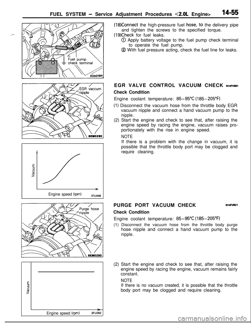
(19)Check for fuel leaks.
@I Apply battery voltage to the fuel pump check terminal
to operate the fuel pump.
@ With fuel pressure acting, check the fuel line for leaks.
A
E2li:>
/ )
Engine speed (rpm)lFU4l6EGR VALVE CONTROL VACUUM CHECK
NlQFVBBlCheck Condition
Engine coolant temperature:
85-95°C (185-205°F)
(1) Disconnect the vacuum hose from the throttle body EGR
vacuum nipple and connect a hand vacuum pump to the
nipple.(2) Start the engine and check to see that, after raising the
engine speed by racing the engine, vacuum raises pro-
portionately with the rise in engine speed.
NOTEIf there is a problem with the change in vacuum, it is
possible that the throttle body port may be clogged and
require cleaning.PURGE PORT VACUUM CHECK
Check Condition
N14FVBClEngine coolant temperature:
85-95°C (185-205°F)
(1) Disconnect the vacuum hose from the throttle body purge
hose nipple and connect a hand vacuum pump to the
nipple.
Engine speed (rpm)3FU262(2) Start the engine and check to see that, after raising the
engine speed by racing the engine, vacuum remains fairly
constant.
NOTE
If there is no vacuum created, it is possible that the throttlebody port may be clogged and require cleaning.
Page 510 of 1216

IL SYSTEM -MPI Svstem InsDection 4.8L Enaine>14-56FUE- _ ~-~~~~~ ~~ ~,~.
MPI SYSTEM INSPECTION <1.8L Engine>COMPONENTS
LncAT’n”’Ignition timing adjustment terminal
Fuel
ourno check terminal
Nl4PAAMAir-flow sensor
Intake air temperature sensor
Barometric pressuresensorCoolant temperature
sensornhibitor switch (A/T)
Inhibitor switch
-xT==-TL--==- IOlAO422
/Pxygen sensor
Page 512 of 1216

14-58FUEL SYSTEM -MPI System Inspection <1.8L Engine>
MALFUNCTION INDICATOR LIGHTNWQAB
Among the self-diagnosis items, a malfunction indicator light
comes on to notify the driver of the emission control items
when an irregularity is detected.
However, when an irregular signal returns to
notmal ‘and the
engine control unit judges that it has returned to normal, the
malfunction indicator light goes out.
Moreover, when the ignition switch is turned off, the light goes
out. Even if the ignition switch is turned on again, the light doesnot come on until the irregularity is detected.
Here, immediately after the ignition switch is turn on, the
malfunction indicator light is lit for 5 seconds to indicate that
the malfunction indicator light operates normally.
Items indicated by the lightening malfunction light
Engine control unit
Oxygen sensor
Air-flow sensor
Intake air temperature sensor
Throttle position sensor
Motor position sensor
Engine coolant temperature sensor
Crank angle sensor
No. 1 cylinder TDC sensor
Barometric pressure sensor
Ignition timing adjustment signal
Injector
Fuel pump
EGR system
The malfunction indicator light lights up when the ignition
timing adjustment terminal is short-circuited
,‘t’o ground.
Consequently, it lights up ,when the ignition timing
adjustment is grounded when adjusting ignition timing,
but in this case there is no abnormality.
MALFUNCTION INDICATOR LIGHT INSPECTlON
When turning on the ignition switch, check that the light comes
on.
NOTElf the light does not come on, check the harness and light for
breakage.SELF-DIAGNOSIS
Nl4PMFaThe engine control unit monitors the input/output signals
(some signals at all times and the others under specified
conditions) of the engine control unit.
Page 513 of 1216

FUEL SYSTEM - MPI System inspection <1.8L Engine>14-59
--..When it is noticed that an irregularity has continued for a
specified time or longer from when the irregular signal is
initially monitored. Passing a certain number, the engine
control unit judges that an irregularity has occurred, memorizesthe malfunction code, and outputs the signal to the
self-diagnosis output terminal.
There are 14 diagnosis items, and the diagnosis results can beread out with a voltmeter.
Moreover, since memorization of the malfunction codes is
backed up directly by the battery, the diagnosis results are
memorized even if the ignition key is turned off. The malfunc-
tion codes will, however, be erased when the battery terminal
or the engine control unit connector is disconnected.
Caution
If the sensor connector is disconnected with the ignition
switch turned on, the malfunction code is memorized. In
this case, disconnect the battery terminal’
(-) for 10seconds or more, and the diagnosis memory will be
erased.The 14 diagnosis items are provided as follows, and if plural
items are activated, they are all indicated sequentially from thesmallest code number.
perature sensor
CautionFor the malfunction code of the ignition timing adjustment
signal, the light for the ignition timing adjustment terminal
lights up when short-circuited to ground.
Consequently, it is output when the ignition timing
adjustment is grounded when adjusting ignition timing,
but in this case there is not abnormality.
CHECK PROCEDURE (SELF-DIAGNOSIS)N14PCAElPrecautions for Operation
(1) When battery voltage is low, no detection of failure is
possible. Be sure to check the battery for voltage and otherconditions before starting the test.
(2) Diagnosis item is erased if the battery or the engine controlunit connector is disconnected. Do not disconnect the
battery before the diagnosis result is completely read.
(3) After check and correction are over, disconnect ground
cable for
10 seconds or more from negative terminal of
battery and connect it again to make sure that failure code
is erased.
Page 514 of 1216

14-60FUEL SYSTEM - MPI Svstem lnwection <1.8L Engine>
7 MPI
diagnosis
LGround
DIAGNOSIS CHART (FAULT TREE)output
preference
orderDiagnosis item
1Engrne control
unit
2 2Oxygen sensor Oxygen sensor
3 3Air flow sensor Air flow sensor
4 4Intake air Intake airtemperature sensor temperature sensor
5 5Throttle position Throttle positionsensor sensor
6 6Motor position Motor positionsensor sensor
INSPECTION PROCEDURE - USING VOLTMETERN14PCAGl
(1) Connect an analogue voltmeter to the self-diagnosis con-,z
nectar.
‘~(2) Turn ignition switch to ON, and indication of engine control
unit memory contents will immediately start. If the system
is in normal condition, pointer of voltmeter indicates normalpattern. If any abnormality is in memory, the pointer of
voltmeter will deflect, indicating abnormal item as de-
scribed in “Diagnosis Chart”.
After recording the abnormal item, check and repair each
part according to the check items in “Diagnosis Chart”.
(3) If the defective parts have been repaired, disconnect the
negative terminal of battery cable for
10 seconds or more
and connect it again to make sure that the abnormal code
has been erased.
N14PRACDiagnosis code
Output signal pattern
:1
12A0104
12A0104
12A0104
12A0104
:JJlJJ--
12A0104
LII
12A0104
No.
-
11Retained
12Retained
14
15MemoryCheck item (Remedy)
-(ll#ace engine control
l Harness and connectorl Fuel, pressurel Injectors
(Replace if defective)
l Intake air leaks0 Oxygen sensor
l Harness and connector
(If harness and connector
are normal, replace airflow sensor assembly.)
Page 515 of 1216

FUEL SYSTEM - MPI System Inspection <1.8L Engine>
outputDiagnosis code
referenceDiagnosis itemCheck item (Remedy)
orderOutput signal patternNo.Memory
7Engine coolantRetainedl Harness and connectortemperature sensor
:-rlrLn- 2’
l Engine coolant temper-
ature sensor
12A0107
8Crank angle sensor
:nn 22
Retainedl Harness and connector
(If harness and connector
are normal, replacedistributor assembly.)
12A0107
9No. 1 cylinder top
dead center sensorH
Lnn 23
Retainedl Harness and connector
(If harness and connector
are normal, replacedistributor assembly.)
12A0107
10Vehicle speed sensor24Retainedl Harness and connector
(reed switch)H
Lu 1 nnJln
l Vehicle speed sensor
(reed switch)
12A0107
11Barometric pressure25Retainedl Harness and connector
sensorH
u I nl-uvln
(If harness and connector
are normal, replace
Lbarometric pressure
12A0107sensor assembly.)
12Ignition timing adjust-36-l Harness and connectorment signalH
LUUI nluvuuL
12R0468
13Injector
:m 41
Retainedl Harness and connector0 Injector coil resistance
12A0105
14Fuel pump42Retainedl Harness and connectorH0 Control relay
LUUUI nn
12A0105
15EGR
H
u u u u-inn
l EGRvalvel EGR valve control sole-Lnoid valve
12A0105l EGR valve control vacuurr
16Normal state---H
Ln
12A0104
NOTEReplace the engine control unit if a malfunction code is output although the inspection reveals that there is no problem with the check
items.
Page 516 of 1216

14-62FUEL SYSTEM - MPI System Inspection <1.8L Engine>
INTAKE AIR TEMPERATURE SENSORNlmNABAir flow sensor
side connectorINSPECTION(1) Disconnect the air flow sensor connectors.
(2) Measure resistance between terminals
@ and @.
6FUO622
Temperature “C PF)Resistance kR
0 (32)6.0
20(68)2.780(176)
0.4(3) Measure resistance while heating the sensor using a hair
drier.
Temperature “C (“F)Resistance kfi
HigherSmaller(4) If the value deviates from the standard value or the
resistance remains unchanged, replace the air flow sensor
assembly.
ENGINE COOLANT TEMPERATURE SENSOR
NWQABE
INSPECTION(1) Remove engine coolant temperature sensor from the
intake manifold.
(2) With temperature sensing portion of engine
cool?nttemperature sensor immersed in hot water, check resist-
ance.16R1251
Temperature “C (“F)Resi’stance kQ
0 (32)5.920(68)
2.5
40 (104)2.7
80(176)0.3(3) If the resistance deviates from the standard value greatly,
replace the sensor.
INSTALLATION(1) Apply specified sealant to threaded portion and tighten to
specified torque.
Specified sealant: MOPAR Part No.4318034
or equivalent
Specified torque: 20
- 40 Nm (15 - 29 ftlbs.)(2) Fasten harness connectors securely.