Page 540 of 1216

14-86FUEL SYSTEM - Throttle Bodv 4.8L Enaine>
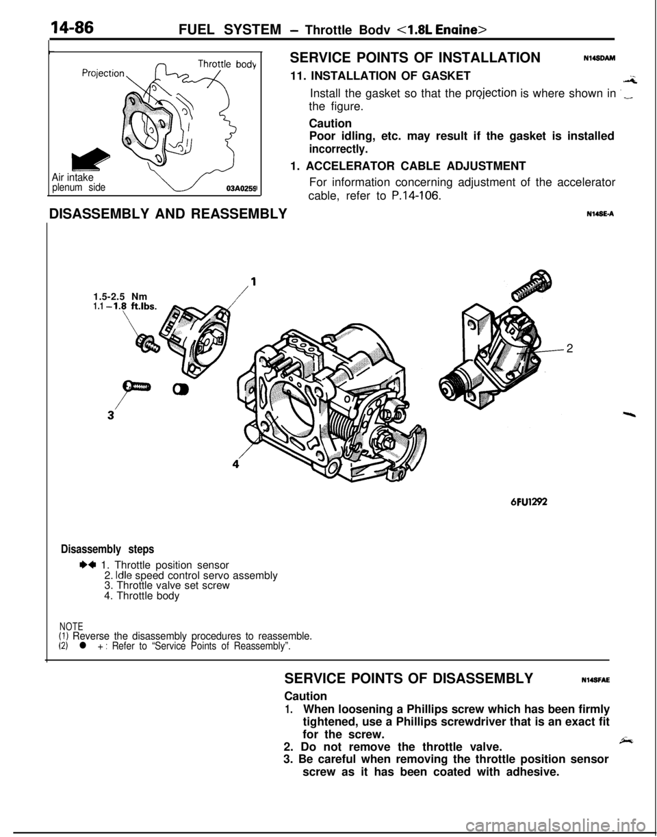
Air intakeplenum sideISERVICE POINTS OF INSTALLATION
Nl4sDAM11. INSTALLATION OF GASKET
.aInstall the gasket so that the
projection is where shown in ‘_the figure.
Caution
Poor idling, etc. may result if the gasket is installed
incorrectly.1. ACCELERATOR CABLE ADJUSTMENT
For information concerning adjustment of the accelerator
cable, refer to
P.14-106.DISASSEMBLY AND REASSEMBLYN14SE-A
1.5-2.5 Nm
/’1.12
6FU1292
Disassembly steps
I)4 1. Throttle position sensor
2. Idle speed control servo assembly
3. Throttle valve set screw
4. Throttle body
NOTE(1) Reverse the disassembly procedures to reassemble.(2) l + : Refer to “Service Points of Reassembly”.SERVICE POINTS OF DISASSEMBLYN14SFAE
Caution
1.When loosening a Phillips screw which has been firmly
tightened, use a Phillips screwdriver that is an exact fit
for the screw.
2. Do not remove the throttle valve.
,&3. Be careful when removing the throttle position sensor
screw as it has been coated with adhesive.
Page 541 of 1216

FUEL SYSTEM - Throttle Bodv <1.8L Engine>
Throttle position
sensor connectorINSPECTIONN14SHAC4
THROTTLE POSITION SENSOR CONTINUITY CHECK
(1) Measure resistance between terminals
@ and @ of the
throttle position sensor using a circuit tester.
Standard value: 3.5-6.5
kSZ(2) Check sensor body for cracks and damages.
6FU1398
I
control servo
connector
6FU1277
IIDLE SPEED CONTROL SERVO OPERATION INSPECTIONIDLE SPEED CONTROL SERVO CONTINUITY CHECK
Measure resistance between terminals @and @ using a circuittester.
Standard value: 5-35
Q [at 20°C (68”F)I
CautionApply only a 6V DC or lower voltage. Application of higher
voltage could cause locking of the servo gears.
(1) Connect 6V DC to terminals @ and @ and check that the
idle speed control servo extends and retracts by itself.
Idle speed controlservo motion
I
IWhen terminal @ is @(RetractsI
IWhen terminal @ is @)ExtendsI(2) If the idle speed control servo does not move, replace the
idle speed control servo assembly.
THROTTLE BODY COMPONENTS CLEANING
(1) Clean all components, but the following components must
not be cleaned by using a cleaning agent.
l Throttle position sensor
l Idle speed control servo assembly
The insulation of these components will be damaged if theyare immersed in a cleaning agent. They should be cleaned
by using only a piece of cloth.
(2) Check for clogging of the vacuum port or passage. Clean
the vacuum passage by using compressed air.
Page 542 of 1216

14-88FUEL SYSTEM - Throttle Body 4.8L Engine>
,
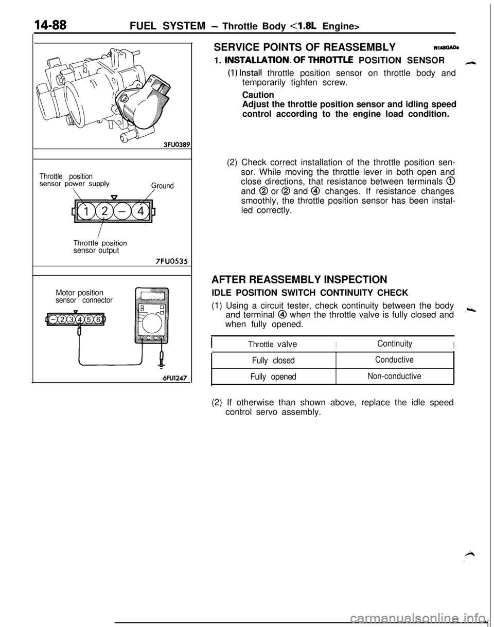
Throttle position
round
sensor output
7FUO535
Motor positionsensor connector
6FU1247SERVICE POINTS OF REASSEMBLYN14SGADa
1. INSTALLATlON.OF THROlTLE POSITION SENSOR
H
(1) Install throttle position sensor on throttle body and
temporarily tighten screw.
Caution
Adjust the throttle position sensor and idling speed
control according to the engine load condition.
(2) Check correct installation of the throttle position sen-
sor. While moving the throttle lever in both open and
close directions, that resistance between terminals
@and
@ or @ and @ changes. If resistance changes
smoothly, the throttle position sensor has been instal-
led correctly.
AFTER REASSEMBLY INSPECTION
IDLE POSITION SWITCH CONTINUITY CHECK
(1) Using a circuit tester, check continuity between the body
and terminal
@I when the throttle valve is fully closed and,riwhen fully opened.
Throttle valveIContinuityI
Fully closed
Fully openedConductive
Non-conductive(2) If otherwise than shown above, replace the idle speed
control servo assembly.
Page 544 of 1216
14-90FUEL SYSTEM - Throttle Body <2.0L DOHC Engine>
r
Air intake
plenum side
03AO259JDISASSEMBLY AND REASSEMBLYSERVICE POINTS OF INSTALLAtlON
Nl49DAU15. INSTALLATION OF GASKET
GInstall the gasket so that the projection is where shown in
._the figure.
Caution
Poor idling, etc. may result if the gasket is installed
incorrectly.
1.5-2.5 Nm
1.1-1.8 ftlbs.
Nl49C92.5-4.5
Nm1.8-3.3 ft.lbs.MU1427
Disassembly steps
1. Throttle position sensor
2. Idle position speed control servo
3. Idle position switch
4. Adjusting nut
5. Throttle body
NOTEReverse the disassembly procedures to reassemble.
Page 545 of 1216

FUEL SYSTEM - Throttle Bodv <2.0L DOHC Erwini+
i
6FU1244
Ground
Throttle
position
sensor
output
Throttle
position
sensorpower-source 6FUO7X
7FUOOlO
ISERVICE
~POINTS OF DISASSEMBLYNl4SFAF
Caution
1.When loosening a Phillips screw which, has been firmlytightened, use a Phillips screwdriverthat is an exact fit
for the screw.
2. Do not remove the throttle valve.
”
3.Be careful when removing the throtite pos?ion sensor
screw and the idle speed control servo- screw as they
have been coated with adhesive.
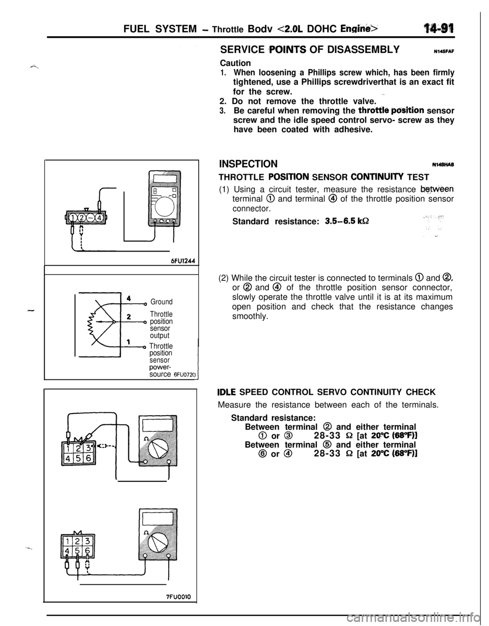
INSPECTIONNl4SNABTHROTTLE
POStTlON SENSOR CONTtNUlTY TEST
(1) Using a circuit tester, measure the resistance
beweenterminal
@ and terminal @ of the throttle position sensor
connector.Standard resistance:
3.5-6.5 k&2(2) While the circuit tester is connected to terminals
@ and @,or @ and @ of the throttle position sensor connector,
slowly operate the throttle valve until it is at its maximum
open position and check that the resistance changes
smoothly.
tDLE SPEED CONTROL SERVO CONTINUITY CHECK
Measure the resistance between each of the terminals.
Standard resistance:
Between terminal @ and either terminal
0 or 028-33 Q [at 29X t6WF)lBetween terminal
0 and either terminal@ or
@I28-33 P [at 20°C (68”F)l
Page 546 of 1216

14-92FUEL SYSTEM- Throttle Bodv <2.0L DOHC Engine>
Iw--
7FUOOl I
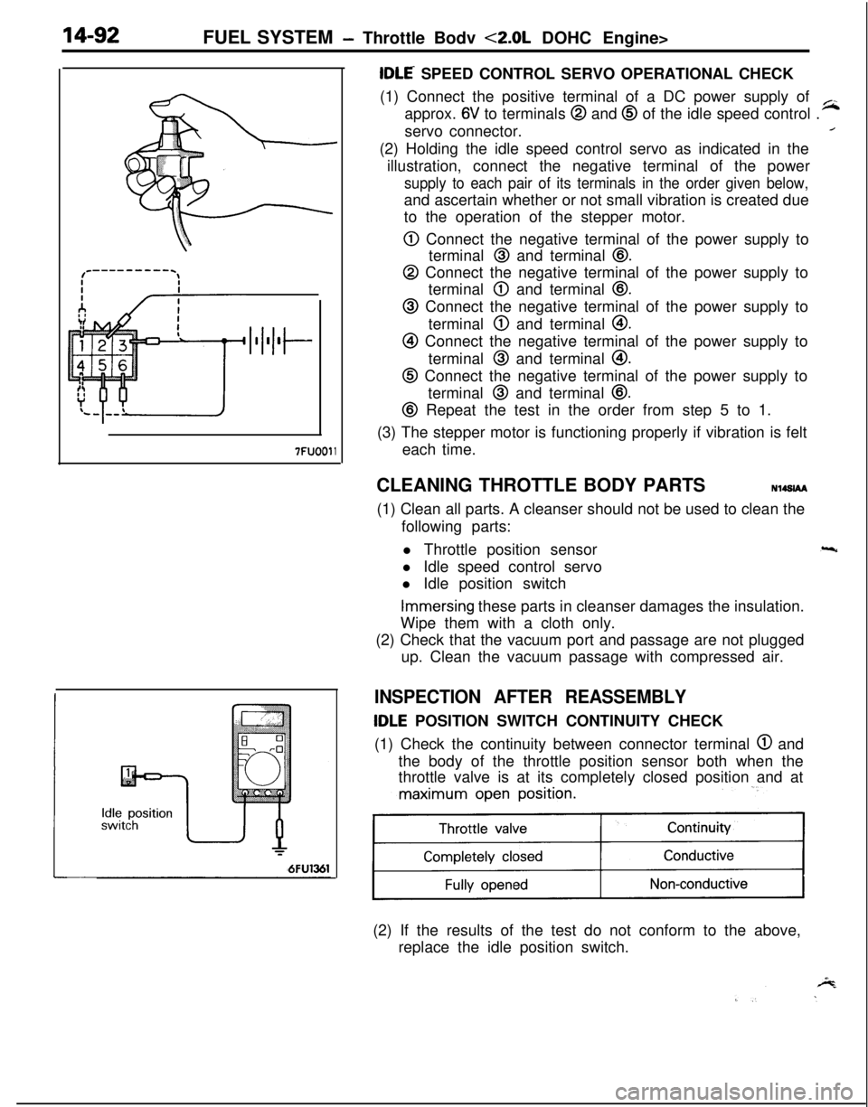
tDLE SPEED CONTROL SERVO OPERATIONAL CHECK
(1) Connect the positive terminal of a DC power supply of
approx.
6V to terminals @ and @ of the idle speed control .
~servo connector.
/(2) Holding the idle speed control servo as indicated in the
illustration, connect the negative terminal of the power
supply to each pair of its terminals in the order given below,and ascertain whether or not small vibration is created due
to the operation of the stepper motor.
0 Connect the negative terminal of the power supply to
terminal
@ and terminal @.
@ Connect the negative terminal of the power supply to
terminal
@ and terminal @I.
@ Connect the negative terminal of the power supply to
terminal
@ and terminal @I.
@I Connect the negative terminal of the power supply to
terminal
@ and terminal @I.
@ Connect the negative terminal of the power supply to
terminal
@ and terminal @.
@ Repeat the test in the order from step 5 to 1.
(3) The stepper motor is functioning properly if vibration is felt
each time.
CLEANING THROTTLE BODY PARTSN14SlAA
(1) Clean all parts. A cleanser should not be used to clean the
following parts:
l Throttle position sensor
l Idle speed control servo
l Idle position switch
Immersing these parts in cleanser damages the insulation.
Wipe them with a cloth only.
(2) Check that the vacuum port and passage are not plugged
up. Clean the vacuum passage with compressed air.
INSPECTION AFTER REASSEMBLY
tDLE POSITION SWITCH CONTINUITY CHECK
(1) Check the continuity between connector terminal
@ and
the body of the throttle position sensor both when the
throttle valve is at its completely closed position and at
maximum open position.
11(2) If the results of the test do not conform to the above,
replace the idle position switch.
Page 564 of 1216

AUTO-CRUISE CONTROL SYSTEM - Troubleshooting
TROUBLESHOOTINGN14,EBPWThe auto-cruise control system performs control functions for
the setting or cancellation of the fixed-speed driving speed
based upon the data provided by input signals. As a result,
when the auto-cruise control system is canceled by abnormal
system operation, the cause of the cancellation is memorized
in a separate circuit by the ECU, thus providing the ECU with
the self-diagnosis function by certain fixed patterns, as well as
the function of being able to check whether or not the ECU’s
input switches or sensor are normal. Thus, by effectively usingthese function, the time required checking and repair can be
shortened.
TROUBLESHOOTING QUICK-REFERENCE CHARTAuto-cruise control system is canceled
when
cancellation not wanted.
Or, the auto-cruise control system cannot
be set after an automatic cancellation.
ECU: Electronic control unit
+-Can the auto-cruise control system be set
No cCheck the diagnosis code
now?(Refer to P.14-122.)II
Yes
Yes
Did the problem
reoccur?Check the diagnosis code
__c (Refer to P.14-122.)
No (new normal)lCheck whether or not, then, the vehicle was driven on a steep
slope.
Page 565 of 1216

AUTO-CRUISE CONTROL SYSTEM - Troubleshooting144w
Auto-cruise control system cannot be set.
NOTEThis chart is to be used, then, for troubleshooting if it is not
possible to use the self-diagnosis for checking.
Prepare to conduct input check.
)( (Refer to P.14lrWhere codes
No.21, 22, 23, 25 and 26disolaved when, with the vehicle stationary,the’ input check codes were recalled?
‘#
No-8
cArc-3 ttie results of all inout checks normals?
L--y--
I
Check resultsProbable causeRemedy
ii”,:” chart
Code 21 remains even though SETSET switch ON mal-Replace the controlNo.2switch
is set to OFF.functionswitch
SET switch input lineRepair the harnessshort-circuit
:-Code 22 remains even though RE-SUME switch is set to OFF.RESUME switch ONmalfunction
RESUME switch input
line short-circuit
Replace the controlswitch
Repair the harnessNo.3
Code 23 is not canceled even if theMalfunction of stopReplace stop lightNo.6stop light switch
is turned OFF bylight switch circuit.switch or repair har-
releasing the brake pedal.ness.
Code 25 does not disappear, andMalfunction of theCheck or repair theNo.4
code 24 does not appear, evenvehicle-speed sensorvehicle speed sensor
though vehicle speed reaches appro-circuit (damaged or dis-circuit.ximately
40 km/h (25 mph) or higher.connected wiring, orshort-circuit)
Code 26 is not canceled even if theclutch switch is turned OFF by re-leasing the clutch pedal.Malfunction of clutch
switch circuit.
Replace clutch switchNo.8or repair harness.
Code 26 is not canceled even if theMalfunction of inhibitorReplace inhibitor switchNo. 7select lever is moved to anything butswitch circuit.or repair harness.
N, P .
the auto-cruise vacuum pump circuit.NOTE_. . . e_,1 (Go to check chart No.5.)IIf the results of the check oT tne auro-crutse vacuum pump
circuit (check chart No. 5) and of the auto-cruise vacuum pump
and actuator itself (P.14-138.) reveal no abnormal
condition,replace
the electronic control unit (ECU).
-.