Page 189 of 1216

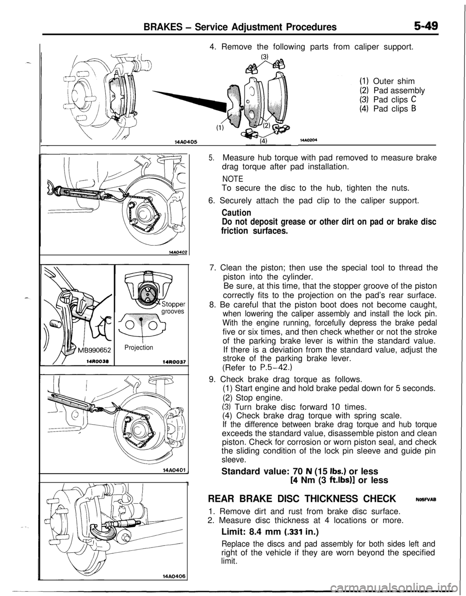
BRAKES - Service Adjustment Procedures5-494. Remove the following parts from caliper support.
14AO405
14AOs
grooves
Q
0 0
Projection
14R0037
14A0401
14AO406
MAO204Outer shim
Pad assembly
Pad clips
CPad clips
B
5.Measure hub torque with pad removed to measure brake
drag torque after pad installation.
NOTETo secure the disc to the hub, tighten the nuts.
6. Securely attach the pad clip to the caliper support.
Caution
Do not deposit grease or other dirt on pad or brake disc
friction surfaces.7. Clean the piston; then use the special tool to thread the
piston into the cylinder.
Be sure, at this time, that the stopper groove of the piston
correctly fits to the projection on the pad’s rear surface.
8. Be careful that the piston boot does not become caught,
when lowering the caliper assembly and install the lock pin.
With the engine running, forcefully depress the brake pedalfive or six times, and then check whether or not the stroke
of the parking brake lever is within the standard value.
If there is a deviation from the standard value, adjust the
stroke of the parking brake lever.
(Refer to
P.5-42.)9. Check brake drag torque as follows.
(1) Start engine and hold brake pedal down for 5 seconds.
(2) Stop engine.
(3) Turn brake disc forward 10 times.
(4) Check brake drag torque with spring scale.
If the difference between brake drag torque and hub torqueexceeds the standard value, disassemble piston and clean
piston. Check for corrosion or worn piston seal, and check
the sliding condition of the lock pin sleeve and guide pin
sleeve.Standard value: 70
N (15 Ibs.) or less
[4 Nm (3 ft.lbs)] or less
REAR BRAKE DISC THICKNESS CHECKNOSWAB
1. Remove dirt and rust from brake disc surface.
2. Measure disc thickness at 4 locations or more.
Limit: 8.4 mm
(.331 in.)
Replace the discs and pad assembly for both sides left andright of the vehicle if they are worn beyond the specified
limit.
Page 190 of 1216
5-50BRAKES - Service Adiustment Procedures
14A.0067
MAO409-
REAR BRAKE DISC RUN-OUT CHECKNOSWAB
1.Remove the caliper support, raise the caliper assembly, and Ir.secure it by using a wire, etc.
-u/2. Place a dial gauge approximately 5 mm
(2 in.) from the
outer circumference of the brake disc, and measure the
run-out of the disc.
Limit: 0.08 mm
(.0031 in.)
NOTETo secure the disc to the hub, tighten the nuts.
REAR BRAKE DISC RUN-OUT CORRECTIONNWFXAA
1.If the run-out of the brake disc is equivalent to or exceeds
the limit specification, change the phase of the disc and
hub, and then measure the run-out again.
rc
NOTEThe procedures for checking by changing the installation
phase of the disc are the same as those for the front brakediscs. (Refer to
P.5-48.)
2.If the problem cannot be corrected by changing the phase
of the brake disc, replace the disc.
Page 191 of 1216
![MITSUBISHI ECLIPSE 1991 Service Manual BRAKES - Service Adjustment Procedures5-51E.C.U. terminal
ILow gear idle condition
[Speed: 5-6 km (3.1-3.16
mph)]Approx.
5V
14A0580When increasing speed
[Speed:
15-20 km (9.3-12.4 mph11OBSERVATION MITSUBISHI ECLIPSE 1991 Service Manual BRAKES - Service Adjustment Procedures5-51E.C.U. terminal
ILow gear idle condition
[Speed: 5-6 km (3.1-3.16
mph)]Approx.
5V
14A0580When increasing speed
[Speed:
15-20 km (9.3-12.4 mph11OBSERVATION](/manual-img/19/57104/w960_57104-190.png)
BRAKES - Service Adjustment Procedures5-51E.C.U. terminal
ILow gear idle condition
[Speed: 5-6 km (3.1-3.16
mph)]Approx.
5V
14A0580When increasing speed
[Speed:
15-20 km (9.3-12.4 mph11OBSERVATION OF WHEEL SPEED SENSOR
OUTPUT VOLTAGE VARIATIONS
ABS>N65FOAO
(1) Jack up the vehicle and release the parking brake.
(2) Disconnect the electronic control unit harness connector,
and measure the speed sensor output voltage at the
vehicle side harness connector.
(3) With an AWD model, put the shift lever in
1st (MTT) or L(A/T) position, rotate the wheels and observe the wave
shape for each wheel. With an FWD model, put the shift
lever in
1st (M/T) or L (AiT) position, rotate the wheels and
observe the wave shape for the front wheels; for the rear
wheels, rotate the wheels by hand and monitor the wave
shape.
NOTEIt is also
allright to actually drive the car.
ISpeed sensor
E.C.U. terminal No.I
IFront leftI14-15I
IFront right31-33I
IRear right28-30I
IRear left1 10-11IWhen wheel speed is slow, the output voltage is low
and it gets higher as the speed increases.
Wave shape monitoring points
IS THE OUTPUTVOLTAGE (AMPLITUDE) TOO LOW OR ISTHERE NO OUTPUT VOLTAGE?
If it is too low, check each wheel speed sensor,
With FWD rear wheels, check the sensor gap.
IS THERE VARIATION IN THE WAVE SHAPE AMPLITUDE?
If the flicker of the amplitude is large, consider shaking
of the axle hub.
IS THERE NOISE IN THE WAVE SHAPE OR DISTORTION?Broken or disconnected wire due to vibration or
installation malfunction of the wheel speed sensor.
Check rotor teeth meshing, breaks, etc.
Approx. 1 OV
14A0501
Page 192 of 1216

5-52BRAKES - Service Adjustment Procedures
16LO312lOWOO
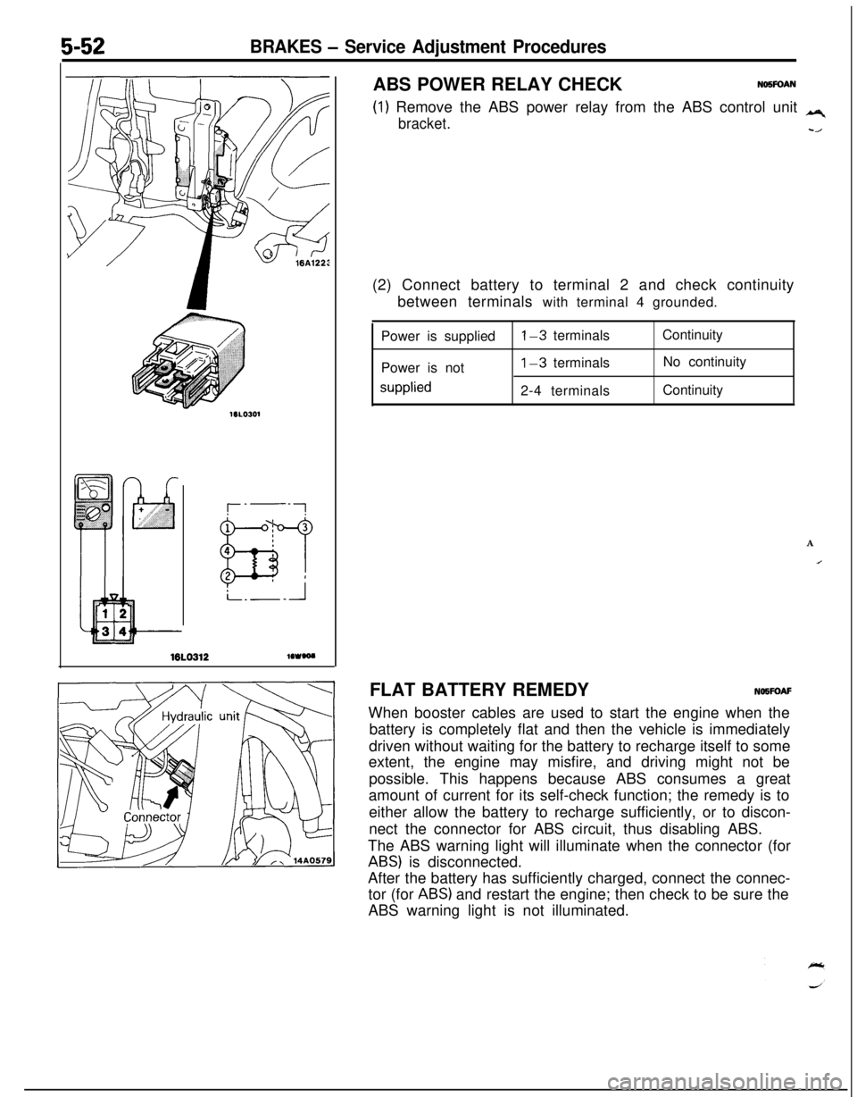
(1) Remove the ABS power relay from the ABS control unit q
bracket.-/ABS POWER RELAY CHECK
NO5FOAN(2) Connect battery to terminal 2 and check continuity
between terminals with terminal 4 grounded.
Power is supplied
Power is not
supplied
l-3 terminals
1-3 terminals
2-4 terminalsContinuity
No continuity
Continuity
A
IFLAT BATTERY REMEDYNOWOAF
When booster cables are used to start the engine when the
battery is completely flat and then the vehicle is immediately
driven without waiting for the battery to recharge itself to some
extent, the engine may misfire, and driving might not be
possible. This happens because ABS consumes a great
amount of current for its self-check function; the remedy is to
either allow the battery to recharge sufficiently, or to discon-
nect the connector for ABS circuit, thus disabling ABS.
The ABS warning light will illuminate when the connector (for
ABS) is disconnected.
After the battery has sufficiently charged, connect the connec-
tor (for
ABS) and restart the engine; then check to be sure the
ABS warning light is not illuminated.
Page 193 of 1216
Page 194 of 1216
5-54BRAKES -Brake Pedal
Removal steps
IO-15 Nm
7-11 ft.lbs.
\
20-25 Nm
14-18 ft.lbs.I17-26 Nm
12-19 ft.lbs.
18-12 Nm
- 6-9 ft.lbs.- /-
117-11 ft.lbs.
13clutch switch Stop light switchconnectorStop light switch
Clutch switch connector andInter lock switch connector
Return springReturn spring
Clip
Turn over spring
Cotter pin
Washer
Clevis pin
1::16.
1::19.
22.
23.
W 25.
4*26.I)4 27.28.
Brake booster push rod
Pedal and bracket assembly
Clutch pedal mounting nut
Lever assembly
Clutch pedal bracketInter lock switch
Pedal support bracket
Clutch pedal
Bushing
P,;$;d
Brake pedal
14AG451
Fyfeverse the removal procedures to reinstall.
(2) 4* : Refer to “Service Points of Removal”.
(3) l 4 : Refer to “Service Points of Installation”.# m : Non-reusabje parts*: Vehicles with auto-cruise control system
SERVICE POINTS OF REMOVAL
NO5GBAHa
26. REMOVAL OF PEDAL RODUsing a plastic hammer, remove the pedal rod from the
pedal support bracket.
Page 195 of 1216

BRAKES - Brake Pedal5-55
14L0142No continuity
Continuity
mm
t.16 in.)
14LO171
:Vehicles with auto-cruiseontrol svstem>
14A0256
14ll0050
INSPECTIONNoMicAll Check the bushing for wear.
l Check the brake pedal for bend or twisting.
l Check the brake pedal return spring for ‘damage.
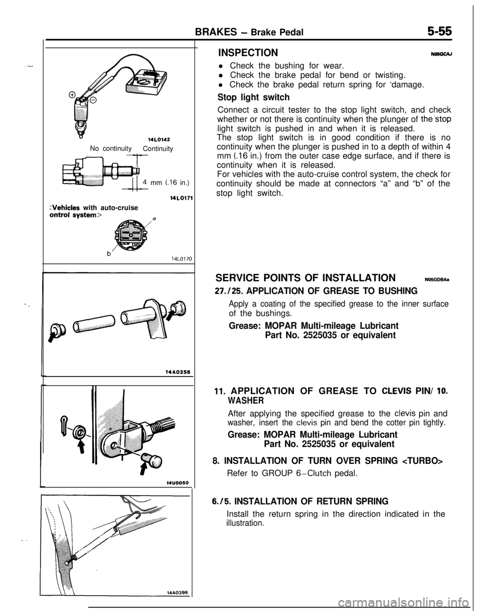
Stop light switchConnect a circuit tester to the stop light switch, and check
whether or not there is continuity when the plunger of the’stop
light switch is pushed in and when it is released.
The stop light switch is in good condition if there is no
continuity when the plunger is pushed in to a depth of within 4
mm
(.I6 in.) from the outer case edge surface, and if there is
continuity when it is released.
For vehicles with the auto-cruise control system, the check for
continuity should be made at connectors “a” and “b” of the
stop light switch.
SERVICE POINTS OF INSTALLATIONN05GDBAa
27.125. APPLICATION OF GREASE TO BUSHING
Apply a coating of the specified grease to the inner surfaceof the bushings.
Grease: MOPAR Multi-mileage Lubricant
Part No. 2525035 or equivalent
11. APPLICATION OF GREASE TO CLEVIS PIN/ IO.
WASHERAfter applying the specified grease to the
clevis pin and
washer, insert the clevis pin and bend the cotter pin tightly.
Grease: MOPAR Multi-mileage Lubricant
Part No. 2525035 or equivalent
8. INSTALLATION OF TURN OVER SPRING Refer to GROUP
6-Clutch pedal.
6.15. INSTALLATION OF RETURN SPRINGInstall the return spring in the direction indicated in the
illustration.
Page 196 of 1216
5-56BRAKES -Master Cylinder
MASTER CYLINDERREMOVAL AND INSTALLATION
Pre-removal Operation
l Draining of Brake FluidPost-installation Operationl supplying Brake Fluidl Bleeding(Refer to P.5-45.1l Adjustment of Brake Pedal(Refer to P.5-41.)
Removal steps
/8-12 Nm
6-S Mbs.
14A02491. Fluid level sensor connector
2. Brake tubes
3. Reservoir hoses
4. Master cylinder
5. Reservoir
6. Bracket
NOTE
l 4Adjustment of clearance between brake(I) Reverse the removal procedures to reinstall.
booster push rod and primary piston(2) l + : Refer to “Service Points of Installation”.
14110053SERVICE POINTS OF INSTALLATIONNWlDAOa
. ADJUSTMENT OF CLEARANCE BETWEEN BRAKE
BOOSTER PUSH ‘ROD AND PRIMARY PISTONAdjust the clearance (A) between the brake booster push
rod and primary piston as follows:
m
J