Page 761 of 1216

MANUAL TRANSAXLE - Clutch Housing Assembly
SERVICE POINTS OF DISASSEMBLY
2f-67
MD998019
\
\
- Control
J$p--lever
201082
MD998\�w
-
20108:
Needle bearing’ ’
20601:
Socketwrench
I’ I20108!
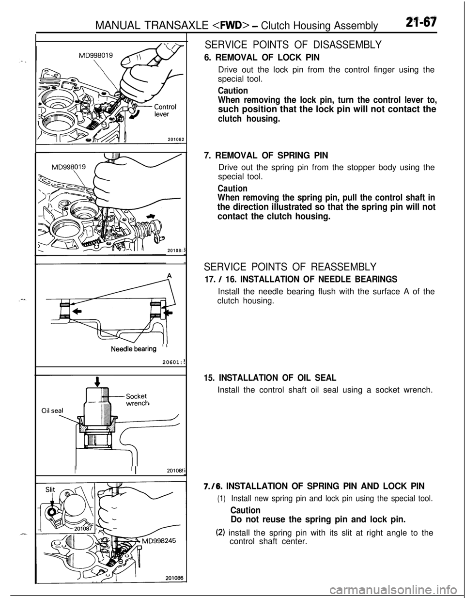
6. REMOVAL OF LOCK PINDrive out the lock pin from the control finger using the
special tool.
Caution
When removing the lock pin, turn the control lever to,such position that the lock pin will not contact the
clutch housing.
7. REMOVAL OF SPRING PINDrive out the spring pin from the stopper body using the
special tool.
Caution
When removing the spring pin, pull the control shaft in
the direction illustrated so that the spring pin will not
contact the clutch housing.
SERVICE POINTS OF REASSEMBLY
17. / 16. INSTALLATION OF NEEDLE BEARINGSInstall the needle bearing flush with the surface A of the
clutch housing.
15. INSTALLATION OF OIL SEALInstall the control shaft oil seal using a socket wrench.7./6.
INSTALLATION OF SPRING PIN AND LOCK PIN
(1)Install new spring pin and lock pin using the special tool.
Caution
Do not reuse the spring pin and lock pin.
(2) install the spring pin with its slit at right angle to the
control shaft center.
Page 762 of 1216
21-68MANUAL TRANSAXLE - General Information
MANUAL TRANSAXLE
GENERAL INFORMATION
lnpu
Dnve bevel gearIClutch housing
1st speecBearing retainer
\
gear
;t-2ndspeed synchronizer assembly
2nd speed gear
3rd speed gear
3rd-4th speed synchronizer assembly
4th speed gear
I .
5th speed gear
intermediate gear
ii\IntermediategearCenter shaft
Viscous coupling
Front differential
\Cent& differential
Front output shaft
,&
--
APLTFM0014
Page 768 of 1216

21-74MANUAL TRANSAXLE - Specifications
Part nameThickness mm (in.)Identification
symbolPart No.
Spacer
1.61
(.0634)61MD722094(For adjustment of driven bevel gear trainpreload)
1.64
(.0646)64MD7220951.67
(0657)67MD722096
1.70(.0669)70MD7220971.73
(0681)73MD7220981.76
(.0693)76M D7220991.79
(0705)79MD7221 00
1.82
(0717)82MD7221 011.85
(.0328)85MD7221 02
1.88
(.0740)88MD7221 03
1.91
(.0752)91MD7221 04
1.94
(0764)94MD722105Spacer
0.13
(0051)13MD720353(For adjustment Of driven bevel gear
mOWIt)o,16 ( 0063)16M D7203540.19
(0075)19MD7203550.22
(.0087)22MD7203560.25
(.0098)25MD7203570.28(.Ol
IO)28MD7203580.31
(0122)31MD7203590.34
(0134)34MD7203600.37
(0146)37MD7203610.40
(0517)40M D7203620.43
(.0169)43MD7203630.46
(0181)46MD7203640.49
(.0193)49MD7203650.52
(0205)52MD720366
TORQUE SPECIFICATIONSNZlCC-B
TRANSAXLEItems
Bell housing cover mounting bolt
Starter motor mounting bolt
Transaxle mount bracket mounting bolt
Shift cable and select cable bracket mounting bolt
Rear cover mounting bolt
Transaxle case mounting bolt
Clutch release cylinder mounting bolt
Clutch tube to transaxle assembly
Under cover
Transaxle mounting bolt
[I2 mm (47 in.) diameter bolt]
Transaxle mounting bolt [IO mm
(40 in.) diameter bolt]
Transaxle mounting bolt [8 mm (.31 in.) diameter bolt]
Tie rod end to knuckleNm
ft.lbs.
IO-127-9
27-34
20-25
60-8043-58
15-22
11-1635-42
26-3035-42
26-3015-22
11-1615-22
11-169-13
7-1043-55
32-39
30-3522-25
IO-127-9
24-3517-25
Page 770 of 1216

21-76MANUAL TRANSAXLE -Specifications/Special Tools
SEALANTS AND ADHESIVESNZlCE-B
TransaxleH-
1
-/Items
Transaxle case-clutch housing mating surfaces
Transaxle case-adapter mating surfaces
Adapter-rear cover mating surfaces
Front differential drive gear bolts
Center differential drive gear bolts
Bearing retainer screw (flush head screw)
Reverse brake cone mounting screw bolts
Air breatherSpecified sealants and adhesives
Mitsubishi genuine part
No.997740or equivalent
MOPAR part
No.4318031 or MOPAR part
No. 4318032 or equivalent
MOPAR part
No.4318025 or equivalent
TransferItems
Adapter-extension housing mating surfacesSpecified sealants and adhesives
Mitsubishi genuine part No.
MD997740or equivalent
Air breatherMOPAR part
No.4318025 or equivalent
SPECIAL TOOLSNZlDA-B AI
NllmherName
I Use,“I. .-. * ,--.
~ MD99801 9
.-...-Lock pin extractor---Removal of spring pin and lock pin
MD998245Lock pin installerInstallation of spring pin and lock pin
0
MD998304Oil seal installerInstallation of front output shaft bearing and
transfer extention housing oil seal
MD998320Bearing installer
Installation of input shaft bearing and input
shaft gear
Page 776 of 1216

21-82MANUAL TRANSAXLE - Transaxle
TRANSAXLE
REMOVAL AND INSTALLATION
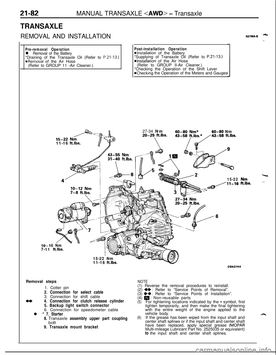
Pre-removal Operationl Removal of the Battery*Draining of the Transaxle Oil (Refer to P.Zl-13.)
@Removal of the Air Hose
(Refer to GROUP 11 -Air Cleaner.)IO-1
7-1111-16
ftlbs.
Post-installation Operation@Installation of the Battery
*Supplying of Transaxle Oil (Refer to P.21-13.)*Installation of the Air Hose
(Refer to GROUP II-Air Cleaner.)
*Checking the Operation of the Shift Lever
@Checking the Operation of the Meters and Gauges
27-34 Nm
60-60 Nm*60-80 Nm20-25 ft.lbs.
\
43-58/t.,b~43-58 ft.lbs.
15-22
6 Nm
ftlbs.
15-22 Nm
vt11-16
ft.lbs.Removal steps
1. Cotter pin
2. Connection for select cable
3. Connection for shift cable
*I)4. Connection for clutch release cylinder
5. Backup light switch connector
6. Connection for speedometer cable
l * 7. Starter
8.
A;;saxle assembly upper part coupling
9. Transaxle mount bracket
NZlMA-B -
,“rr,s.
09AOl44
NOTE(1) Reverse the removal procedures to reinstall.
(2)
+e : Refer to “Service Points of Removal”.
(3) I)+ : Refer to “Service Points of Installation”.
(4) m : Non-reusable parts(5)For tightening locations indicated by the * symbol, first
tighten temporarily, and then make the final tightening
with the entire weight of the engine applied to the
(6)vehicle body.
If the grease has been wiped from the input shaft and
center shaft splines or if the input shaft and center shaft
have been replaced, apply special grease
(MOPARMulti-mileage Lubricant Part No. 2525035 or equivalent)
to the input shaft and center shaft splines.
Page 778 of 1216

21-84MANUAL TRANSAXLE - Transaxle
r) ’TransaxlellKfil1
SERVICE POINTS OF REMOVALN21MBAV4. DISCONNECTION OF CLUTCH RELEASE CYLINDER/
12. TIE ROD
END/l4. LOWER ARM BALL JOINT
Refer to
P.21-21.15. DISCONNECTION OF DRIVE SHAFT
Insert a pry bar between the transaxle case and the drive
shaft, and then pry the drive shaft from the transaxle.
Caution
1.Do not pull on the drive shaft; doing so will damage
the inboard joint; be sure to use the pry bar.
2.Do not insert the pry bar so deep as to damaged theoil seal.
(1) Take out the drive shaft by lightly tapping the drive shaftT.J. case with a plastic hammer.
NOTERemove the drive shaft with the hub and knuckle, etc.,
as an assembly.
Caution
1. Removing the drive shaft from the,, outboa,rd
joint side can cause damage to the inboard joint.Always use a plastic hammer, etc., to remove
the drive shaft.
2. Tapping on the center bearing can damage it.
Never tap on the bearing.
(2) Keep the removed drive shaft as far away from the
transaxle case as possible, and secure (by using rope,
etc.) the joints to the body so that it does not fall.
17. REMOVAL OF FRONT EXHAUST PIPE
Refer to GROUP
1 l-Exhaust Pipe and Main Muffler.
18. REMOVAL OF TRANSFER ASSEMBLY
Refer to
P.21-85.23. REMOVAL OF TRANSAXLE ASSEMBLY
Refer to
P.21-22.
SERVICE POINTS OF INSTALLATION!’23. REMOVAL OF TRANSAXLE ASSEMBLY
Refer to
P.21-22.15. INSTALLATION OF DRIVE SHAFT
Refer to
P.21-22.7. INSTALLATION OF STARTER
Refer to
P.21-22.
NZlMDAQ
Page 782 of 1216
21-88MANUAL TRANSAXLE - Transaxle Assembly15-22 Nm
11-15 ft.lbs.
-.@&35-42 Nm
26-30 ft.lbs.
\15-22 Nm
11-15 ft.lbs.
/4?2250013
Disassembly steps
38. Clutch oil line bracket
l + 39. Transaxle case
l + 40. Oil guide
l + 41. Oil guide
42. Outer race
l + 43. Spacer
l * 44. Spacer
45. Stopper bracket
l 46. Oil seal
47. Reverse shift lever assembly
48. Reverse shift lever shoe
49. Reverse idler gear shaft
50. Reverse idler gear
51. Front output shaft assembly
52. Needle bearing
53. Front differentialNOTE
(I) Reverse the disassembly procedures to reassemble.(2) l + : Refer to “Service Points of Reassembly”.(3) m : Non-reusable parts.
Page 783 of 1216
--MANUAL TRANSAXLE
- Transaxle Assembly6?
Disassembly steps
*I) l + 54. Spring pin+I) l + 55. Spring pin+e e+ 56. Shift rail assemblyl + 57. Bolt58. Bearing retainer
+e l + 59.Intermediate gear assembly
s: W 60. Input shaft assembly
61. Outer racel 4 66. Oil seal
l 4 67. Oil seal
l + 68. Magnet
W 69. Magnet holder
70. Clutch housing assembly
NOTE
TFM0666
4*62. Outer race
63. Oil guide(1) Reverse the disassembly procedures to reassemble.(2) +I) : Refer to “Service Points of Disassembly”.4*64. Outer race
(3) ~~ : Refer to “Service Points of Reassembly”.
l 4 65. Oil seal(4) m : Non-reusable parts.