Page 409 of 1216
ENGINE <2.0L DOHC Engine> -Front Case, Oil Pump and Silent Shaft9-1256E
N026:(2) Install the front case assembly through a new front
case gasket and temporarily tighten the flange bolts
(other than those for tightening the filter bracket).
(3) Mount the oil filter bracket with oil filter bracket gasket.
Then, install the four bolts with washers.
(4) Tighten the bolts to specification.
NOTE
Bolts indicated by the * symbol should be tightened at atorque of 27-34 Nm
(20-25 ft.1b.s.).20. INSTALLATION OF DRIVEN GEAR BOLT
(1) Insert a Phillips screwdriver into a hole in the left side ofthe cylinder block to lock the silent shaft.
(2) Secure the oil pump driven gear onto the left silent
shaft by tightening the driven gear bolt to specified
torque.18. INSTALLATION OF PLUG CAP
(1) Install a new O-ring to the groove of front case.
(2) Using the special tool, install the plug cap and tighten tospecified torque.
Page 497 of 1216

FUEL SYSTEM - Service Adjustment Procedures <1.8L Engine>14-43
(14)lf it is out of specification, adjust by loosing the throttle
position sensor mounting screws and rotating the throttle
position sensor. After adjustment, tighten the screws
firmly.
NOTEClockwise rotation of the throttle position sensor increases
the output voltage.
Throttle position
sensor
t-/ /I
(15)Set the ignition switch at OFF.
(16)Adjust the free play of the accelerator cable.
(17)Reconnect the connectors of the idle speed control servo.
(18)Remove the voltmeter.
(19)Start the engine and check that the engine is running at thecurb idle speed.
Curb idle speed:
700f 100 rpm
(20)Set the ignition switch at OFF, disconnect the negative
battery cable and reconnect it more than
10 seconds later
(By doing so, the memory storing the diagnosis data duringthe idle speed control adjustment is cleared.)
(21)Restart the engine, let it run at idle for about 5 minutes, andcheck that the engine is running in good idle quality.
THROTTLE BODY (THROTTLE VALVE AREA)
CLEANING
NllRCK
(1) Warm up the engine, then stop it.
(2) Remove the air intake hose from the throttle body.
(3) Spray cleaning solvent into the valve through the throttle
body intake port and leave it for about 5 minutes.
(4) Start the engine, race it several times and idle it for about 1minute. If the idling speed becomes unstable slightly open
the throttle valve to keep the engine running.
(5) If the throttle valve deposits are not removed, repeat steps
(3) and (4).
(6) Attach the air intake hose.
(7) Disconnect the battery terminal for
10 seconds or more,
and then reconnect it.
(8) Adjust the idle speed control and throttle position sensor.
Page 516 of 1216

14-62FUEL SYSTEM - MPI System Inspection <1.8L Engine>
INTAKE AIR TEMPERATURE SENSORNlmNABAir flow sensor
side connectorINSPECTION(1) Disconnect the air flow sensor connectors.
(2) Measure resistance between terminals
@ and @.
6FUO622
Temperature “C PF)Resistance kR
0 (32)6.0
20(68)2.780(176)
0.4(3) Measure resistance while heating the sensor using a hair
drier.
Temperature “C (“F)Resistance kfi
HigherSmaller(4) If the value deviates from the standard value or the
resistance remains unchanged, replace the air flow sensor
assembly.
ENGINE COOLANT TEMPERATURE SENSOR
NWQABE
INSPECTION(1) Remove engine coolant temperature sensor from the
intake manifold.
(2) With temperature sensing portion of engine
cool?nttemperature sensor immersed in hot water, check resist-
ance.16R1251
Temperature “C (“F)Resi’stance kQ
0 (32)5.920(68)
2.5
40 (104)2.7
80(176)0.3(3) If the resistance deviates from the standard value greatly,
replace the sensor.
INSTALLATION(1) Apply specified sealant to threaded portion and tighten to
specified torque.
Specified sealant: MOPAR Part No.4318034
or equivalent
Specified torque: 20
- 40 Nm (15 - 29 ftlbs.)(2) Fasten harness connectors securely.
Page 531 of 1216

FUEL SYSTEM - MPI Svstem InsDection <2.0L DOHC Engine>14-77INSTALLATION
(1) Apply specified sealant to threaded portion and tighten to
specified torque.
Specified sealant: MOPAR Part No.4318034 or
equivalent
Specified torque: 20
- 40 Nm (15 - 29 ft.lbs.1(2) Fasten harness connectors securely.
THROTTLE POSITION SENSOR
INSPECTION
N14QBBKl(1) Disconnect the throttle position sensor connector.
(2) Measure resistance between terminal
@I (sensor ground)
and terminal
@ (sensor power).
Standard value: 3.5
- 6.5 kR(3) Connect a pointer type ohmmeter between terminal
@I(sensor ground) and terminal
@ (sensor output).
(4) Operate the throttle valve slowly from the idle position to
the full open position and check that the resistance changessmoothly in proportion with the throttle valve opening
angle.
6FU1244(5) If the resistance is out of specification, or fails to change
smoothly, replace the throttle position sensor.
Throttle position sensor installation torque:
1.5
- 2.5 Nm (1.1 - 1.8 ft.lbs.)
J II\/ hFU1419IDLE POSITION SWITCH
INSPECTION
N14QKAEa(1) Keeping the acceleration pedal released, check that the
throttle valve lever or the idle position switch is pushed.
NOTEIf it is not pushed, adjust the idle position switch (fixed
speed adjusting screw). (Refer to
P.14-52.)(2) Disconnect the idle position switch connector.
(3) Check the continuity between terminal
@) to the ground.
Page 557 of 1216

-.FUEL SYSTEM
- Fuel Line pnd Vapoi- @f&
L
Mounting
bolts
pipe
03FOOO
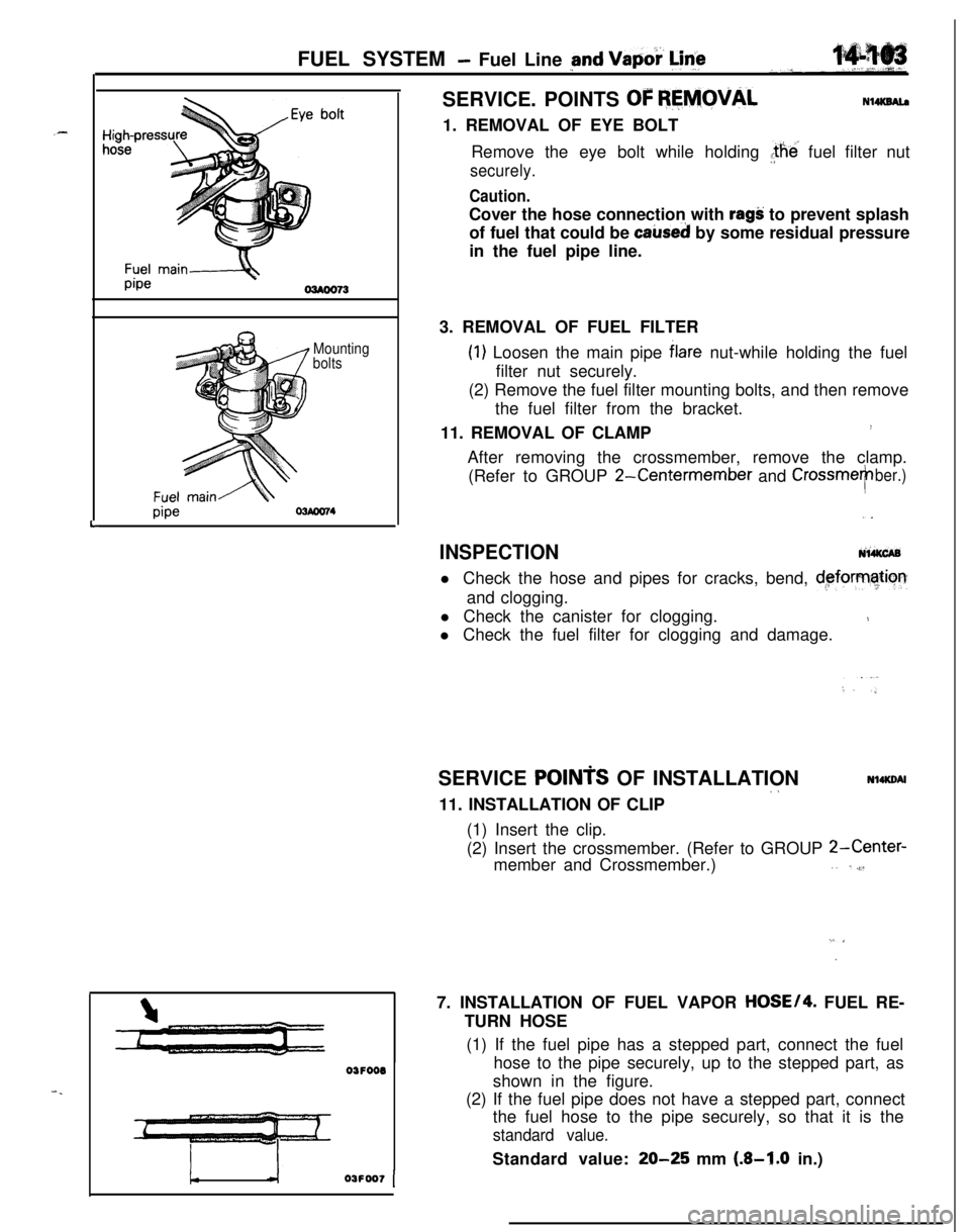
!-03FOO7 [SERVICE. POINTS
OF REMOVALN14KSAl.a1. REMOVAL OF EYE BOLT
Remove the eye bolt while holding the’ fuel filter nut
securely.
Caution.Cover the hose connection with
ragS: to prevent splash
of fuel that could be
caked by some residual pressure
in the fuel pipe line.
3. REMOVAL OF FUEL FILTER
(1) Loosen the main pipe blare nut-while holding the fuel
filter nut securely.
(2) Remove the fuel filter mounting bolts, and then remove
the fuel filter from the bracket.
11. REMOVAL OF CLAMP
!After removing the crossmember, remove the clamp.
(Refer to GROUP
2-Centermember and CrossmeTber.),.
INSPECTIONNi&CABl Check the hose and pipes for cracks, bend,
d,eforrnatiorrand clogging.
l Check the canister for clogging.
1l Check the fuel filter for clogging and damage.
SERVICE
POINTS OF INSTALLATION~aNl4KDAl11. INSTALLATION OF CLIP
(1) Insert the clip.
(2) Insert the crossmember. (Refer to GROUP
2-Center-member and Crossmember.),. ,,$l
”7. INSTALLATION OF FUEL VAPOR
HOSE/4. FUEL RE-
TURN HOSE
(1) If the fuel pipe has a stepped part, connect the fuel
hose to the pipe securely, up to the stepped part, as
shown in the figure.
(2) If the fuel pipe does not have a stepped part, connect
the fuel hose to the pipe securely, so that it is the
standard value.Standard value:
20-25 mm (.&I.0 in.)
Page 558 of 1216

FUEL SYSTEM - Fuel Line and VaDor Line/Fuel Filter
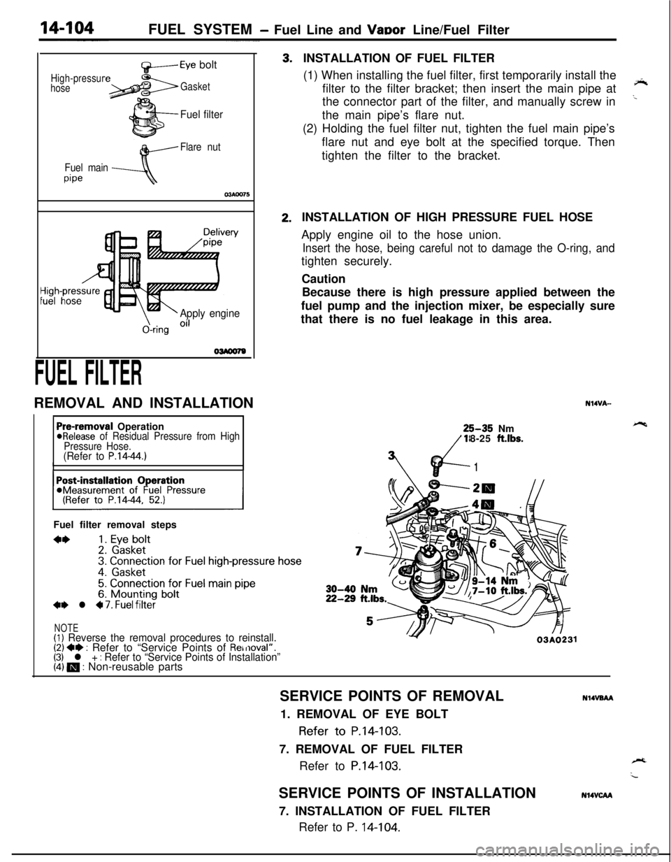
High-pressur
hose
f+-----Eye bolt
Gasket
Fuel filter
Flare nut
Fuel main
pipe
\-Apply engine
&ring Oi’
FUEL FILTERREMOVAL AND INSTALLATION3.2.INSTALLATION OF FUEL FILTER
(1) When installing the fuel filter, first temporarily install the
filter to the filter bracket; then insert the main pipe at
‘*the connector part of the filter, and manually screw in
..the main pipe’s flare nut.
(2) Holding the fuel filter nut, tighten the fuel main pipe’s
flare nut and eye bolt at the specified torque. Then
tighten the filter to the bracket.
Pre-removal Operation@Release of Residual Pressure from High
Pressure Hose.
(Refer to P.14-44.)IIFuel filter removal steps
**1. Eye bolt2. Gasket3. Connection for Fuel high-pressure hose
4. Gasket
5. Connection for Fuel main pipe6. Mounting bolt+e l 4 7. Fuel filter
NOTE(1) Reverse the removal procedures to reinstall.(2) +e : Refer to “Service Points of Removal”.(3) l + : Refer to “Service Points of Installation”(4) m : Non-reusable partsINSTALLATION OF HIGH PRESSURE FUEL HOSE
Apply engine oil to the hose union.
Insert the hose, being careful not to damage the O-ring, andtighten securely.
Caution
Because there is high pressure applied between the
fuel pump and the injection mixer, be especially sure
that there is no fuel leakage in this area.
N14VA-25-35 Nm
18-25
ft.lbs.
vd-
7’
1
Y03A0231SERVICE POINTS OF REMOVAL
NlIVBAA1. REMOVAL OF EYE BOLT
Refer to P.14-103.
7. REMOVAL OF FUEL FILTER
Refer to
P.14-103.SERVICE POINTS OF INSTALLATION
7. INSTALLATION OF FUEL FILTER
Refer to P. 14-104.
N14VCAA
Page 560 of 1216

14-106ENGINE CONTROL - Service Adjustment Procedures
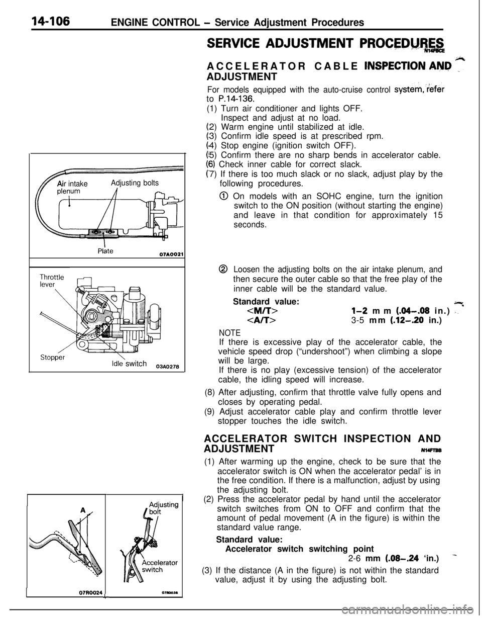
TAir intakeAdjusting bolts
Idle switch03A,,2.8
07RQ024L
I
SERVICE ADJUSTMENT PROCEDM%,&ACCELERATOR CABLE
CNSPECTION AN&I ”ADJUSTMENT
For models equipped with the auto-cruise control systemreferto
P.14-136.(1) Turn air conditioner and lights OFF.
Inspect and adjust at no load.
2) Warm engine until stabilized at idle.
3) Confirm idle speed is at prescribed rpm.
4) Stop engine (ignition switch OFF).
5) Confirm there are no sharp bends in accelerator cable.
6) Check inner cable for correct slack.
7) If there is too much slack or no slack, adjust play by the
following procedures.
@ On models with an SOHC engine, turn the ignition
switch to the ON position (without starting the engine)
and leave in that condition for approximately 15
seconds.@
Loosen the adjusting bolts on the air intake plenum, andthen secure the outer cable so that the free play of the
inner cable will be the standard value.
Standard value:
jlr
l-2 mm (.04-.08 in.) \. *
3-5 mm (.12-.20 in.)
NOTEIf there is excessive play of the accelerator cable, the
vehicle speed drop (“undershoot”) when climbing a slope
will be large.
If there is no play (excessive tension) of the accelerator
cable, the idling speed will increase.
(8) After adjusting, confirm that throttle valve fully opens and
closes by operating pedal.
(9) Adjust accelerator cable play and confirm throttle lever
stopper touches the idle switch.
ACCELERATOR SWITCH INSPECTION AND
ADJUSTMENT
NlWlEB(1) After warming up the engine, check to be sure that the
accelerator switch is ON when the accelerator pedal’ is in
the free condition. If there is a malfunction, adjust by using
the adjusting bolt.
(2) Press the accelerator pedal by hand until the accelerator
switch switches from ON to OFF and confirm that the
amount of pedal movement (A in the figure) is within the
standard value range.
Standard value:
Accelerator switch switching point
2-6 mm
(.08-.24 ‘in.)
(3) If the distance (A in the figure) is not within the standard
value, adjust it by using the adjusting bolt.
Page 562 of 1216

14-108ENGINE CONTROL - Engine Control
INSPECTION
j N%PJCf@l Check the inner and outer cable for damage.
l Check the cable for smooth movement.$+
l Check the accelerator arm for bending.--
l Check the return spring for deterioration.
l Check the connection of bushing to end metal fitting.
l Check the accelerator switch for ON/OFF switching.
SERVICE POINTS OF INSTALLATIONN14DDAP
ll.APPLlCATlON OF GREASE TO RETURN SPRING/
10. ACCELERATOR ARM
Apply multipurpose grease around the each moving point
of the accelerator arm.
Grease: MOPAR Multi-mileage Lubricant
Part No.2525035 or equivalent
8. APPLICATION OF SEALANT TO ACCELERATOR ARM
BRACKETApply the specified sealant to the bolt mounting hole, and
then tighten the accelerator arm bracket.
,%Specified sealant:
3M ATD Part No.8663 or equivalent
4. APPLICATION OF GREASE TO ACCELERATOR ARM
SIDE INNER CABLE/B. BUSHING
(1) Securely install the resin bushing of the accelerator
cable on the end of the accelerator arm.
(2) Apply multipurpose grease around the cable end.
Grease: MOPAR Multi-mileage Lubricant
Part No.2525035 or equivalent