1991 MITSUBISHI 3000GT engine coolant
[x] Cancel search: engine coolantPage 495 of 1146

AUTOMATIC TRANSAXLE - Troubleshootinn23-43
CONVERTER STALL TESTStall test consist of determining maximum engine
speed obtained at full throttle in “D” and
“I?”positions. This test checks torque converter
statoroverrunning clutch operation, and holding ability of
transaxle clutches and low-reverse brake.
Caution
During this test, make sure that no one stand in
front of or behind vehicle.
1. Check transaxle fluid level. Fluid should be at
normal operating temperature
[70 - 80°C (160 -
18O”F)I. Engine coolant should also be at normal
operating temperature
[80 - 90°C (180 - 19O”F)l.2. Apply chocks to both rear wheels.
3. Attach engine tachometer.
4. Apply parking and service brakes fully.
5. Start engine.
6. With selector lever in “D” position, depress
accelerator pedal fully to read engine maximum
rpm. Do not hold throttle wide open any longer
than is necessary to obtain maximum engine
rpm reading, and never longer than 5 seconds at
a time. If more than one stall test is required,
operate engine at approximately 1,000 rpm in
neutral for 2 minutes to cool transaxle fluid
between tests.
Stall speed: 2,200
- 3,200 rpm
7.Place selector lever to “R” position and perform
stall test by the same procedure as in foregoing
item.
Stall Speed Above Specification in “D”
If stall speed is higher than specification, rear clutch
or overrunning clutch of transaxle is slipping. In this
case, perform hydraulic test to locate cause of
slippage.
Stall Speed Above Specification in “R”
If stall speed is higher than specification, front
clutch of transaxle or low-reverse brake is slipping.
In this case, perform hydraulic test to locate cause
of slippage.
Stall Speed Below Specification in “D” and “R”
If stall speed is lower than specification, insufficient
engine output or faulty torque converter is sus-
pected. Check for engine misfiring, ignition timing,
valve clearance, etc. If these are good, torque
converter is faulty.
TRANSAXLE CONTROL
Symptom
Selector lever operationis stiff
Probable cause
Incorrect adjustment of sleeve
Remedy
Adjust
Incorrect adjustment of control cable
Excessive wear of detent plate
Worn contact surfaces of pushbutton
and sleeve
Adjust
Replace
Replace
Starter motor does notMalfunction in inhibitor switchReplace
operate with the selector
lever in the “N” or “P”Incorrect adjustment of control cableAdjust
position
Will not shift to
4-speed
Malfunction of starter relay
Malfunction of OD switchReplace
Replace
1 TSB RevisionI
Page 1083 of 1146

55-1
HEATER, AIR
CONDITIONER
AND VENTILATION
CONTENTSM55AA- -
HEATERS AND AIR CONDITIONING................3HEATER UNIT*........................................................................22
SPECIFICATIONS
....................................................................3REFRIGERANT LINE................................................................35General Specifications
........................................................3RESISTOR................................................................................20Lubricants
............................................................................4SAFETY PRECAUTIONS........................................................9Sealant and Adhesive............................................................4
Service Specifications3SERVICE ADJUSTMENT PROCEDURES............................10........................................................
SPECIAL TOOLS4Charging Procedures............................................................11
i
........................................................................Charging the Refrigerant....................................................12Compressor Drive Belt Adjustment....................................11
HEATERS AND MANUAL AIR CONDITIONER5Compressor Noise................................................................16
................................................16
AIR CONDITIONER SWITCH................................................21Handling Tubing andFittings
Idle-up Operation Check....................................................17
BELT LOCK CONTROLLER20Performance Test................................................................15....................................................
BLOWER ASSEMBLYPower Relay Check............................................................17............................................................23Refrigerant Leak Repair Procedure....................................15COMPRESSOR........................................................................
27TestProcedures....................................................................10
CONDENSER AND CONDENSER FAN MOTOR................33TROUBLESHOOTING............................................................5
ENGINE COOLANT TEMPERATURE SWITCH....................
39VENTILATORS (AIR INLET AND AIR OUTLET)................38
EVAPORATOR
........................................................................
25VENTILATORS (INSTRUMENT PANEL)*............................36
HEATER CONTROL ASSEMBLY*
........................................18CONTINUED ON NEXT PAGE
SUPPLEMENTAL RESTRAINT SYSTEM (SRS)
(1)A Supplemental Restraint System (SRS), which uses a driver-side air bag, has been installed in the 3000GT.(2)The SRS includes the following components: impact sensors, SRS diagnosis unit: SRS warning light, air bagmodule, clock spring, interconnecting wiring. Other SRS-related components (that may have to be
removed/installed in connection with SRS service or maintenance) are indicated in the table of contents byan asterisk (*).
WARNING!(1)Improper service or maintenance of any component of the SRS, or any SRS-related component, can lead to
personal injury or death to service personnel (from inadvertent firing of the air bag) or to the driver (fromrendering the
SRS inoperative).(2) Service or maintenance of any SRS component or SRS-related component must be performed only at anauthorized MITSUBISHI dealer.
(3) MITSUBISHI dealer personnel must thoroughly review this manual, and especially its GROUP 52B
-Supplemental Restraint System (SRS), before beginning any service or maintenance of any component of theSRS or any SRS-related component.
Page 1084 of 1146

55-2FULL AUTO AIR CONDITIONER........................40OTHER PARTS........................................................................62
AIR-CONDITIONER CONTROL PANEL*,POWER TRANSISTOR, BELT LOCK CONTROLLER........57
AIR-CONDITIONER CONTROL UNIT*................................56
REFRIGERANT LINE................................................................62
COMPRESSOR
........................................................................62SAFETY PRECAUTlONS........................................................56
CONDENSER AND CONDENSER FAN MOTOR
................
62SENSORS....................................................................................60
DAMPER CONTROL MOTOR ASSEMBLY*........................
58SERVICE ADJUSTMENT PROCEDURES............................56
ENGINE COOLANT TEMPERATURE SWITCH
....................62
TROUBLESHOOTING............................................................40
Page 1085 of 1146
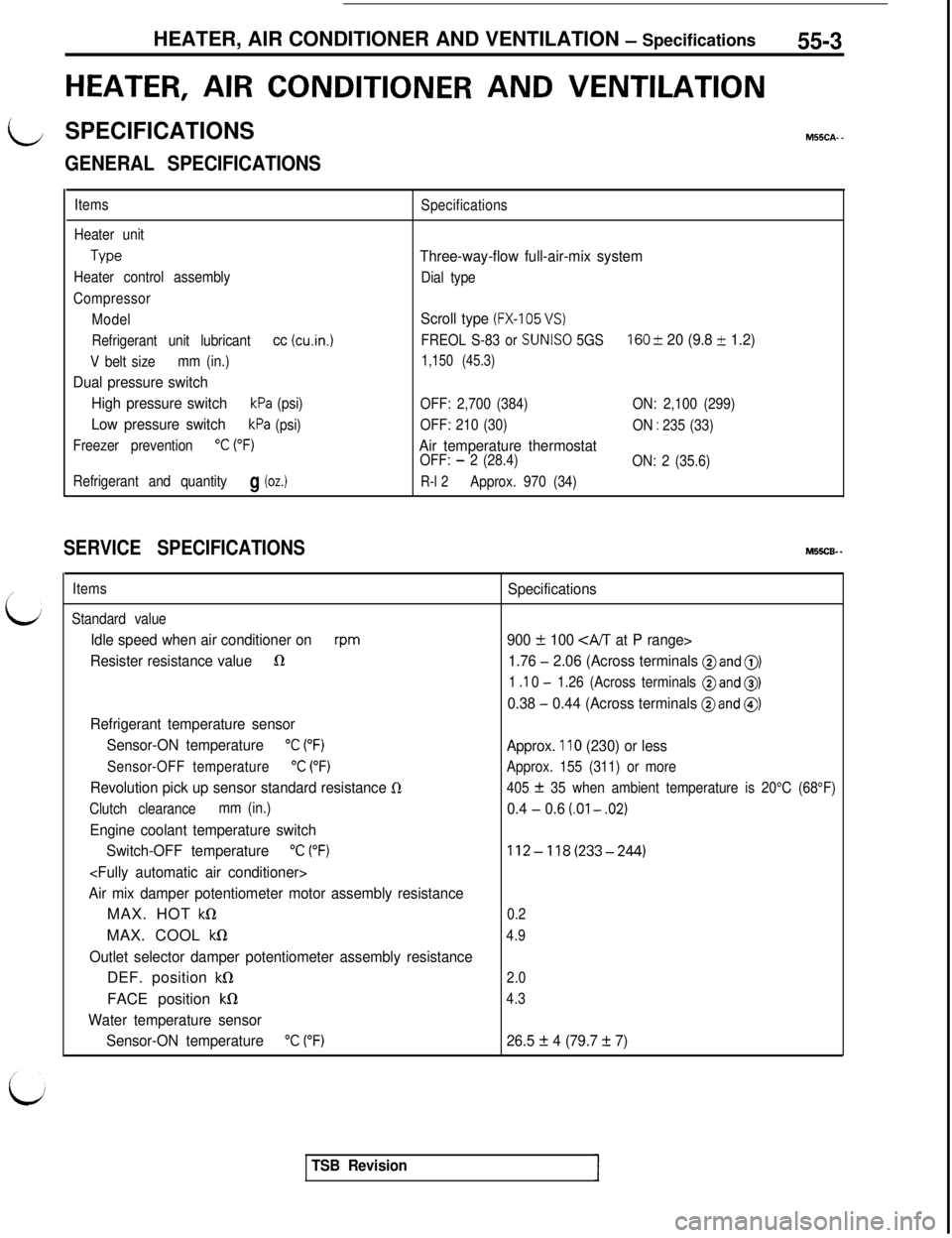
HEATER, AIR CONDITIONER AND VENTILATION - Specifications55-3
HEATER, AIR CONDITIONER AND VENTILATION
LSPECIFICATIONSM55CA. -
/’
L;
GENERAL SPECIFICATIONS
Items
Heater unit
Type
Heater control assembly
Compressor
Model
Refrigerant unit lubricant
cc (cu.in.1
V belt sizemm (in.)
Dual pressure switch
High pressure switch
kPa (psi)
Low pressure switchkPa (psi)
Freezer prevention
“C (“F)
Refrigerant and quantityg (oz.)
Specifications
Three-way-flow full-air-mix system
Dial type
Scroll type (FX-105 VS)
FREOL S-83 or SUNISO 5GS160 & 20 (9.8 + 1.2)
1,150 (45.3)
OFF: 2,700 (384)ON: 2,100 (299)
OFF: 210 (30)
ON
: 235 (33)
Air temperature thermostatOFF: - 2 (28.4)
ON: 2 (35.6)
R-l 2Approx. 970 (34)
SERVICE SPECIFICATIONSM55CB. -
Items
Standard value
Idle speed when air conditioner onrpm
Resister resistance value1R
Refrigerant temperature sensor
Sensor-ON temperature
“C (“F)
Sensor-OFF temperature“C (“F)
Revolution pick up sensor standard resistance 0
Clutch clearancemm (in.)
Engine coolant temperature switch
Switch-OFF temperature
“C (“F)
Air mix damper potentiometer motor assembly resistanceMAX. HOT
kQMAX. COOL
kS1
Outlet selector damper potentiometer assembly resistanceDEF. position
kS1FACE position
kfl
Water temperature sensor
Sensor-ON temperature
“C (“F)
Specifications
900
f 100 CA/T at P range>
1.76
- 2.06 (Across terminals @and 0)
1 .I 0 - 1.26 (Across terminals @and 0)
0.38 - 0.44 (Across terminals @and @)
Approx. 110 (230) or less
Approx. 155 (311) or more
405
f 35 when ambient temperature is 20°C (68°F)
0.4 - 0.6 (.Ol - .02)
112-118(233-244)
0.2
4.9
2.0
4.3
26.5 f 4 (79.7 + 7)
TSB Revision
Page 1086 of 1146
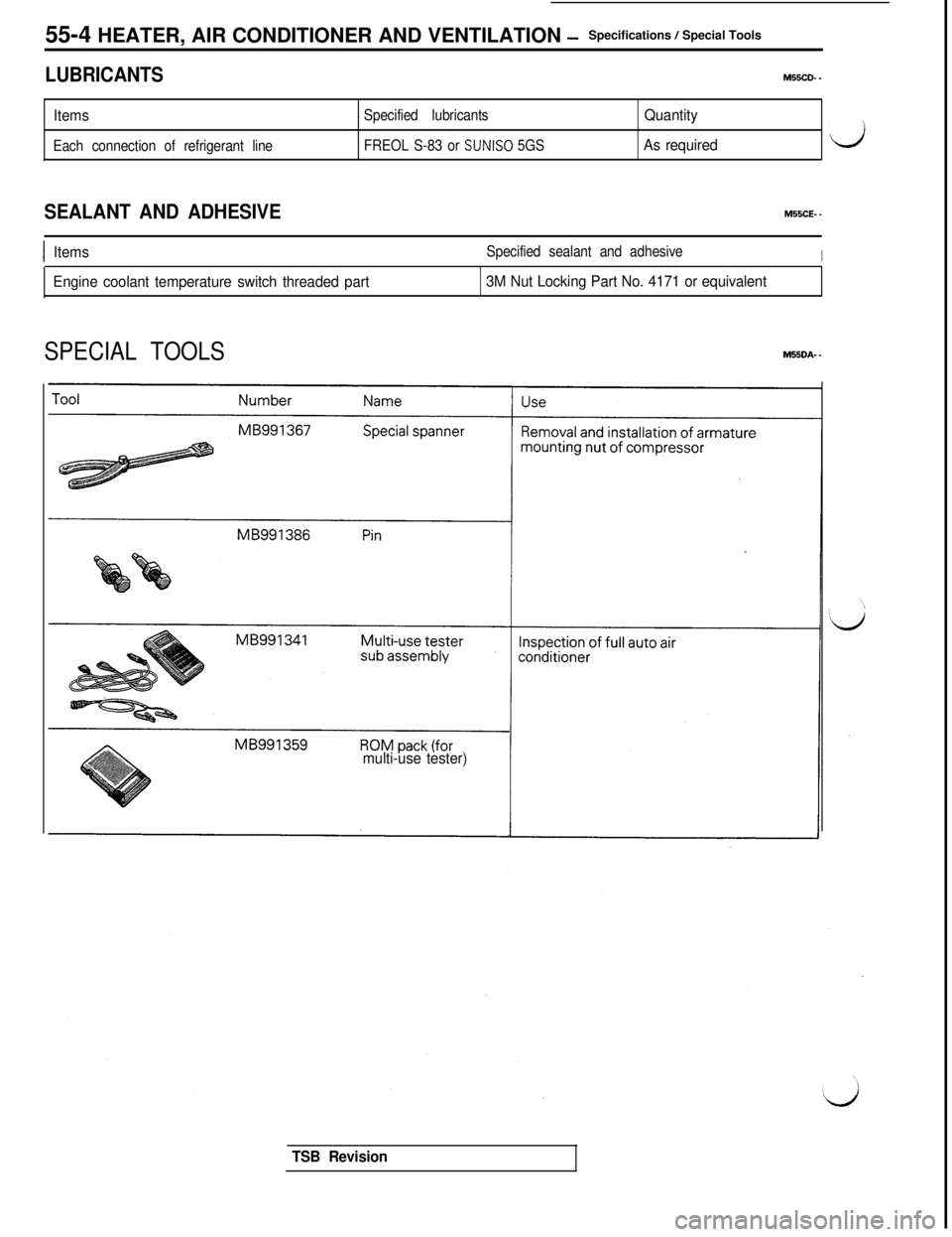
55-4 HEATER, AIR CONDITIONER AND VENTILATION -Specifications / Special Tools
LUBRICANTSM55CD. _
ItemsSpecified lubricants
Each connection of refrigerant lineFREOL S-83 or
SUNISO 5GS
Quantity
As required
SEALANT AND ADHESIVEM55CE- -
IItemsSpecified sealant and adhesiveI
Engine coolant temperature switch threaded part3M Nut Locking Part No. 4171 or equivalent
SPECIAL TOOLSMSSDA- -
multi-use tester)
TSB Revision
Page 1099 of 1146
HEATERS AND MANUAL AIR CbNDlTlONER -Service Adjustment Procedures 55 17
ADJUSTMENT PROCEDURES(1) Select a quiet area for testing. Duplicate conditions as much
as possible. Switch compressor on and off several times to
clearly identify compressor noise.
To duplicate high ambient conditions (high head pressure),
restrict air flow through condenser. Install manifold gauge
set to make sure discharge pressure doesn’t exceed 2,070
kPa (300 psi).
(2) Tighten all compressor mounting bolts, clutch mounting
bolt, and compressor drive belt. Check to assure clutch coil
is tight (no rotation or wobble).
(3) Check refrigerant hoses for rubbing or interference that can
cause unusual noises.
(4) Check refrigerant charge. (See “Charging System”.)
(5) Recheck compressor noise as in Step 1.
(6) If noise still exists, loosen compressor mounting bolts and
retorque. Repeat Step 1.
(7) If noise continues, replace compressor and repeat Step 1.
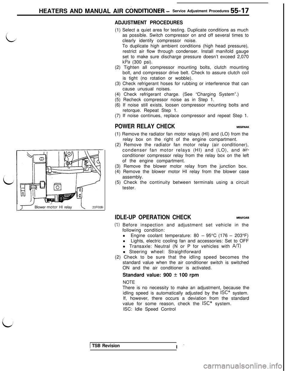
POWER RELAY CHECKMBBFNAK(1) Remove the radiator fan motor relays (HI) and (LO) from the
relay box on the right of the engine compartment.
(2) Remove the radiator fan motor relay (air conditioner),
condenser fan motor relays (HI) and (LO), and
air-conditioner compressor relay from the relay box on the left
of the engine compartment.
(3) Remove the blower motor relay from the junction box.
(4) Remove the blower motor HI relay from the blower case
assembly.
(5) Check the continuity between terminals using a circuit
tester.
J Blower m.otor HI relay\2OFOO6l
IDLE-UP OPERATION CHECKM55FOAB
(1) Before inspection and adjustment set vehicle in the
following condition:
lEngine coolant temperature: 80 - 95°C (176 - 203°F)
lLights, electric cooling fan and accessories: Set to OFF
l Transaxle: Neutral (N or P for vehicles with
A/T)l Steering wheel: Straightforward
(2) Check to be sure that the idling speed becomes the
standard value when the air conditioner switch is switched
ON and the air conditioner is activated.
Standard value: 900
+ 100 rpm
NOTEThere is no necessity to make an adjustment, because the
idling speed is automatically adjusted by the ISC” system.
If, however, there occurs a deviation from the standard
value for some reason, check the ISC” system.
ISC: Idle Speed Control
1 TSB RevisionI -
Page 1121 of 1146
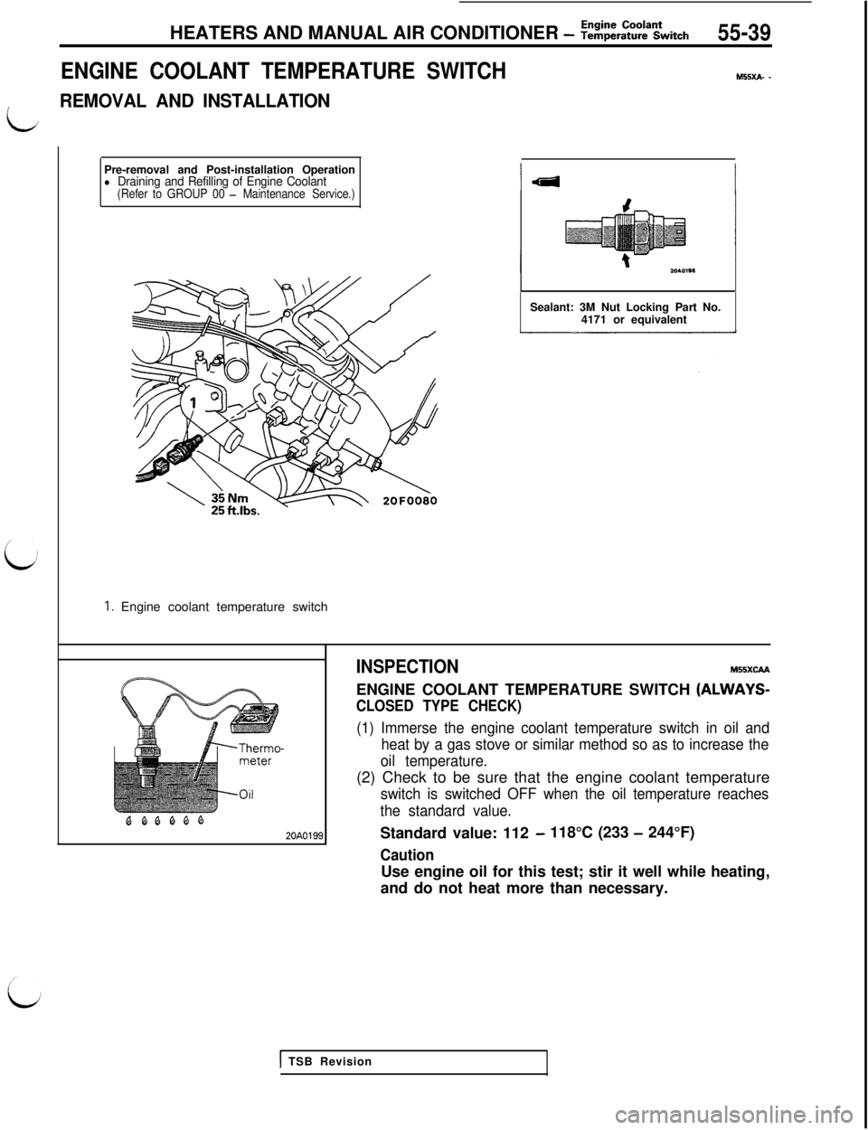
Pre-removal and Post-installation Operationl Draining and Refilling of Engine Coolant(Refer to GROUP 00 - Maintenance Service.)
1. Engine coolant temperature switchHEATERS AND MANUAL AIR CONDITIONER
- Z!&E%Ltch55-39
ENGINE COOLANT TEMPERATURE SWITCH
M55xA- -
L
REMOVAL AND INSTALLATIONSealant: 3M Nut Locking Part No.
4171 or equivalent
BQQQQQ20A0199INSPECTION
MSSXCAAENGINE COOLANT TEMPERATURE SWITCH
(ALWAYS-
CLOSED TYPE CHECK)
(1) Immerse the engine coolant temperature switch in oil and
heat by a gas stove or similar method so as to increase the
oil temperature.(2) Check to be sure that the engine coolant temperature
switch is switched OFF when the oil temperature reaches
the standard value.Standard value: 112
- 118°C (233 - 244°F)
CautionUse engine oil for this test; stir it well while heating,
and do not heat more than necessary.
1 TSB Revision
Page 1130 of 1146
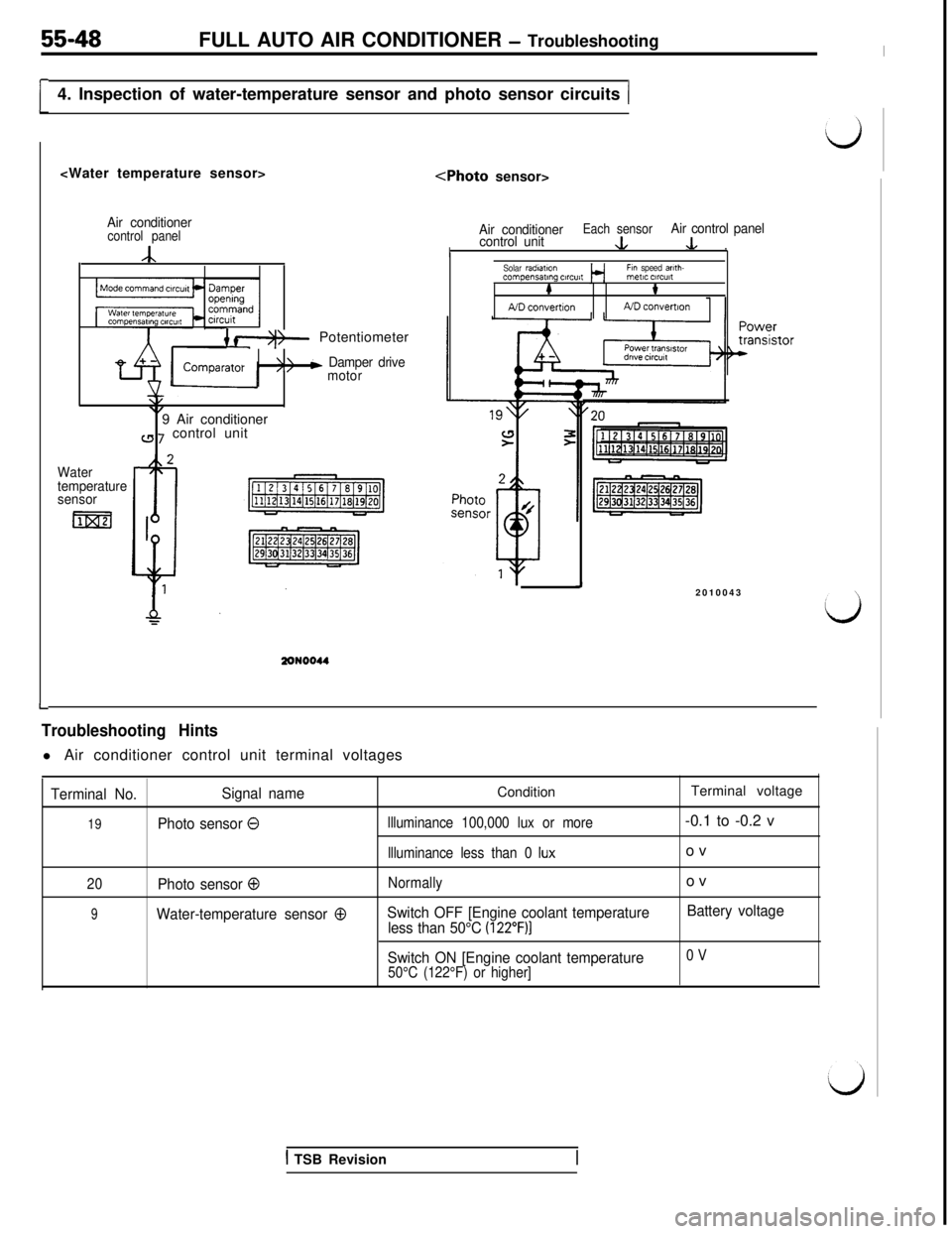
55-48FULL AUTO AIR CONDITIONER - Troubleshooting
[4. Inspection of water-temperature sensor and photo sensor circuits (
Air conditionercontrol panel
A
{ f*)- Potentiometer
‘>/b Damper drive
motor
\/\,9 Air conditioner
a 7 control unit
Water
temperature
sensor
m
Air conditionerEach sensorcontrol unit&
Air control panel
I.L .Solar radmtmnFin speed arlth-compensating ClrC”itmetIC ClrCUlt#t
A/D convertionND convemon
J2010043
I-
Troubleshooting Hintsl Air conditioner control unit terminal voltages
Terminal No.Signal nameConditionTerminal voltage
19Photo sensor 0llluminance 100,000 lux or more-0.1 to -0.2 v
llluminance less than 0 Iuxov
20Photo sensor 0Normallyov
9Water-temperature sensor 0Switch OFF [Engine coolant temperature
less than 50°C (122”F)]
Battery voltage
Switch ON [Engine coolant temperature
0 V
50°C (122°F) or higher]
1 TSB Revision