1991 MITSUBISHI 3000GT display
[x] Cancel search: displayPage 1013 of 1146
c
LJ
SUPPLEMENTAL RESTRAINT SYSTEM (SRS) - General information52B-3
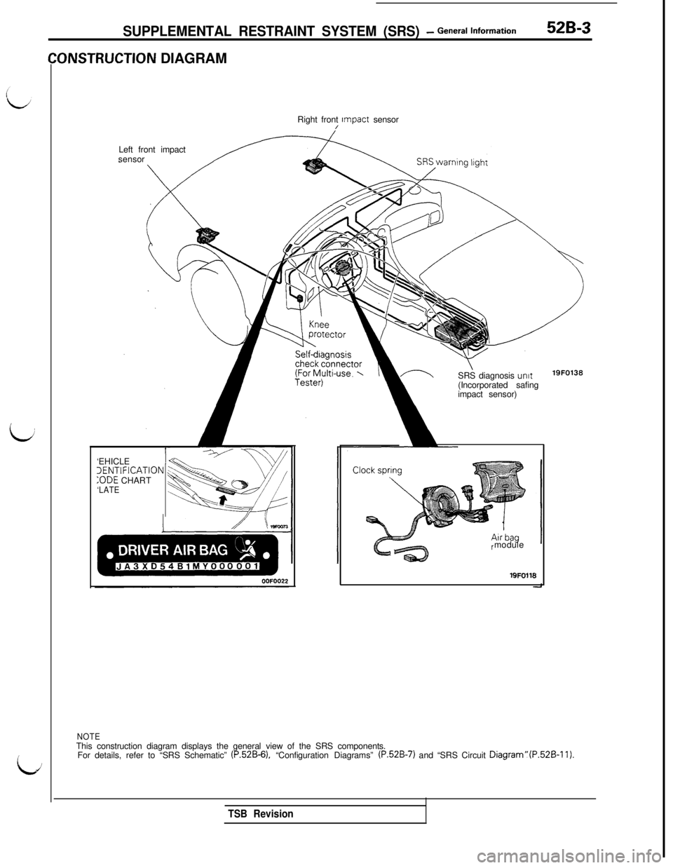
ONSTRUCTION DIAGRAM
Right front Impact sensor
/Left front impact
sensor
SRS diagnosis
unit(Incorporated safing
impact sensor)19FO138‘EHICLE
1~ENTIFICATION:ODE CHART
‘LATEmodulelQFO118
NOTEThis construction diagram displays the general view of the SRS components.
For details, refer to “SRS Schematic”
(P.52B-6). “Configuration Diagrams” (P.52B-7) and “SRS Circuit Diagram”(P.52B-11).
TSB Revision
Page 1028 of 1146
52B-18 SUPPLEMENTAL RESTRAINT SYSTEM (SRS) - Troubleshooting
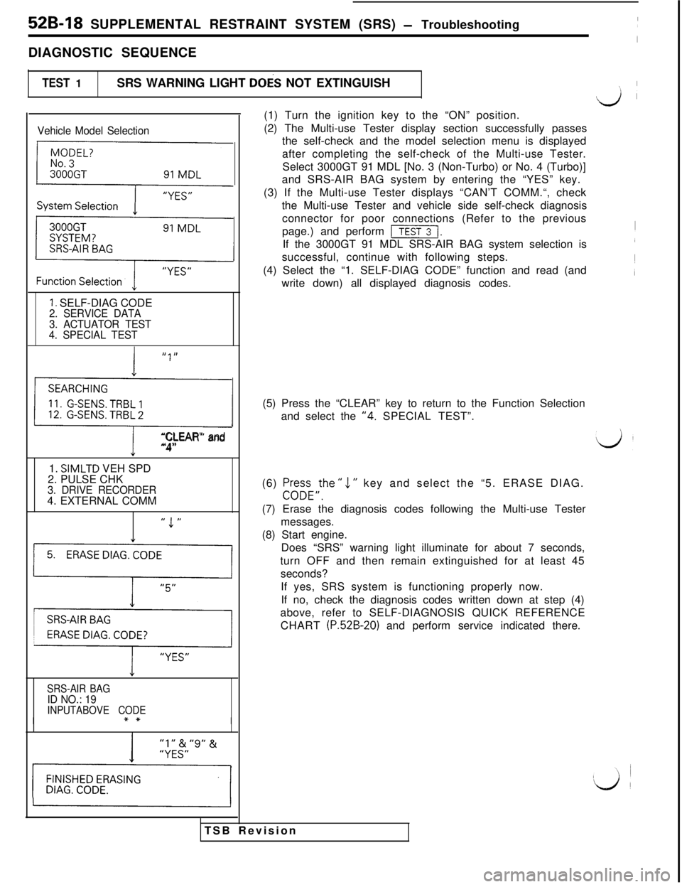
DIAGNOSTIC SEQUENCE
TEST 1SRS WARNING LIGHT DOES NOT EXTINGUISH
\1 I
Vehicle Model Selection
{
F
1. SELF-DIAG CODE2. SERVICE DATA
3. ACTUATOR TEST
4. SPECIAL TEST
,, I,
0
“CLEAR” and“4”1.
SIMLTD VEH SPD
2. PULSE CHK
3. DRIVE RECORDER4. EXTERNAL COMM
” 1 ”
1’1
y,,
SRS-AIR BAGID NO.: 19INPUTABOVE CODE
I(1) Turn the ignition key to the “ON” position.
(2) The Multi-use Tester display section successfully passes
the self-check and the model selection menu is displayed
after completing the self-check of the Multi-use Tester.
Select 3000GT 91 MDL [No. 3 (Non-Turbo) or No. 4 (Turbo)]
and SRS-AIR BAG system by entering the “YES” key.
(3) If the Multi-use Tester displays “CAN’T COMM.“, check
the Multi-use Tester and vehicle side self-check diagnosis
TSB Revisionconnector for poor connections (Refer to the previous
page.) and perform
[I.If the 3000GT 91 MDL SRS-AIR BAG system selection is
successful, continue with following steps.
(4) Select the “1. SELF-DIAG CODE” function and read (and
write down) all displayed diagnosis codes.
(5) Press the “CLEAR” key to return to the Function Selection
and select the
“4. SPECIAL TEST”.
(6) Pr+FE,the ”
1 ” key and select the “5. ERASE DIAG.
(7) Erase the diagnosis codes following the Multi-use Tester
messages.
(8) Start engine.
Does “SRS” warning light illuminate for about 7 seconds,
turn OFF and then remain extinguished for at least 45
seconds?
If yes, SRS system is functioning properly now.
If no, check the diagnosis codes written down at step (4)
above, refer to SELF-DIAGNOSIS QUICK REFERENCE
CHART
(P.52B-20) and perform service indicated there.
Page 1029 of 1146
SUPPLEMENTAL RESTRAINT SYSTEM (SRS) - Troubleshooting 52B-19
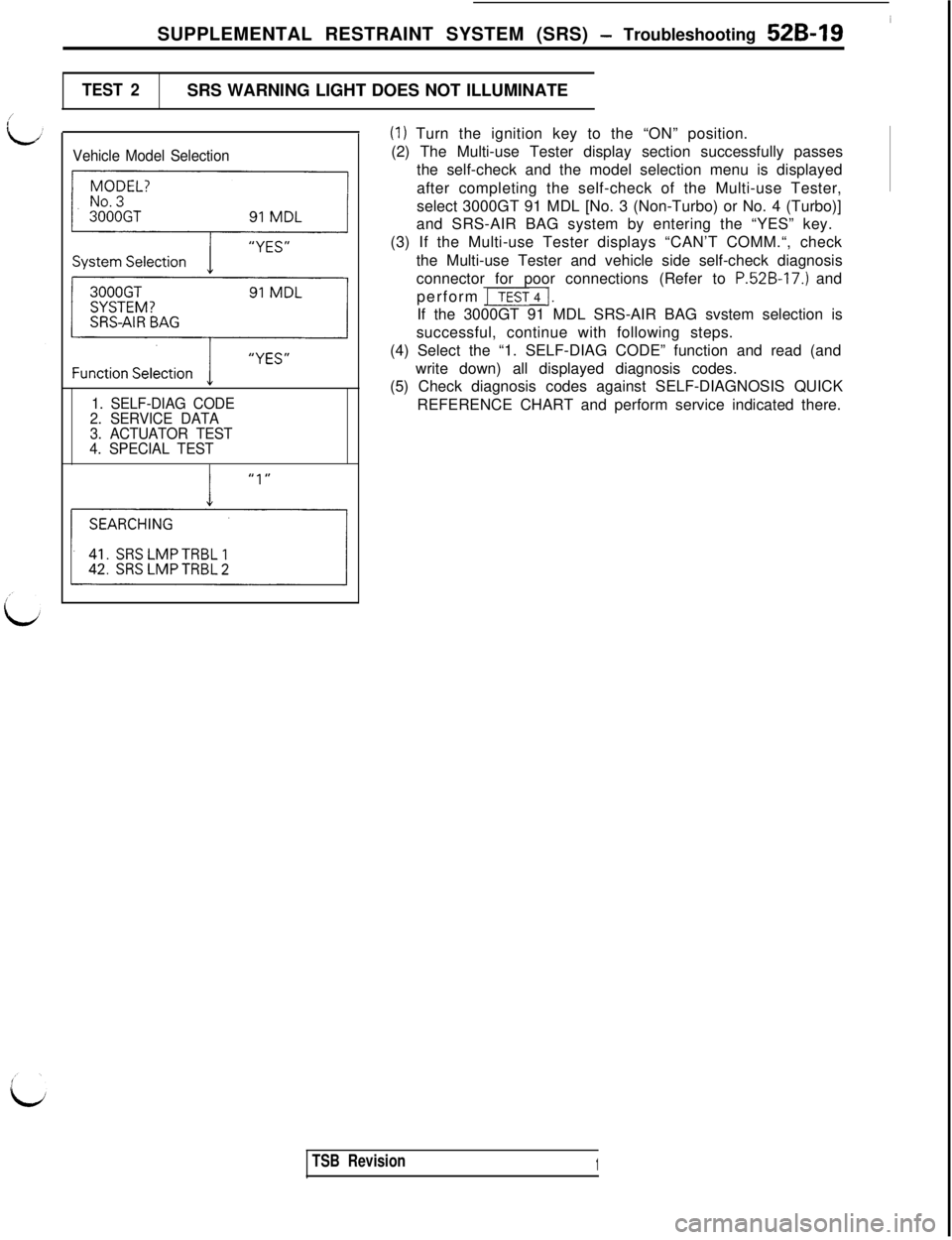
TEST 2SRS WARNING LIGHT DOES NOT ILLUMINATE
Vehicle Model Selection
-
pc-y-y
1. SELF-DIAG CODE
2. SERVICE DATA
3. ACTUATOR TEST
4. SPECIAL TEST
(1) Turn the ignition key to the “ON” position.
(2) The Multi-use Tester display section successfully passes
the self-check and the model selection menu is displayed
after completing the self-check of the Multi-use Tester,
select 3000GT 91 MDL [No. 3 (Non-Turbo) or No. 4 (Turbo)]
and SRS-AIR BAG system by entering the “YES” key.
(3) If the Multi-use Tester displays “CAN’T COMM.“, check
the Multi-use Tester and vehicle side self-check diagnosis
connector for poor connections (Refer to
P.52B-17.) and
perform
ITEST 4 1.If the 3000GT 91 MDL SRS-AIR BAG svstem selection is
successful, continue with following steps.
(4) Select the “1. SELF-DIAG CODE” function and read (and
write down) all displayed diagnosis codes.
(5) Check diagnosis codes against SELF-DIAGNOSIS QUICK
REFERENCE CHART and perform service indicated there.
TSB Revision1
Page 1064 of 1146
52B-54 SUPPLEMENTAL RESTRAINT SYSTEM (SRS) - ZZ%K%~g~~~s
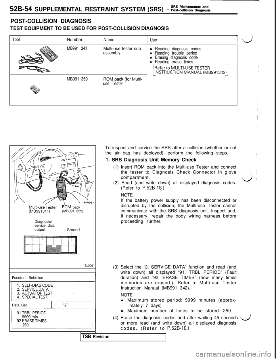
POST-COLLISION DIAGNOSISTEST EQUIPMENT TO BE USED FOR POST-COLLISION DIAGNOSIS
ToolNumberName
Use
MB991 341Multi-use tester subassemblyl Reading diagnosis codesl Reading trouble periodl Erasing diagnosis codel Reading erase times
MB991 359
ROM pack (for Multi-
use Tester
Multi-usejesterR'OM pack(MB991341)(MB991 359)
Diagnosis/
service data
output
I
16LOO9'Function Selection
Data ListTo inspect and service the SRS after a collision (whether or not
the air bag has deployed), perform the following steps.
1. SRS Diagnosis Unit Memory Check
(1) Insert ROM pack into the Multi-use Tester and connect
the tester to Diagnosis Check Connector in glove
compartment.
‘I i(2) Read (and write down) all displayed diagnosis codes.J’(Refer to
P.52B-18.)
NOTEIf the battery power supply has been disconnected or
disrupted by the collision, the Multi-use Tester cannot
communicate with the SRS diagnosis unit. Inspect and,
if necessary, repair the body wiring harness before
proceeding further.
(3) Select the “2. SERVICE DATA” function and read (and
write down) all displayed “91. TRBL PERIOD” (Fault
duration) and “92. ERASE TIMES” (how many times
memories are erased.). Refer to Multi-use Tester
Instruction Manual (MB991 342).
NOTEl Maximum stored period: 9999 minutes (approx-
imately 7 days)
l Maximum number of times to be stored: 250
(4) Erase the diagnosis codes and after waiting 45 seconds
‘dor more read (and write down) all displayed diagnosis
codes. (Refer to P.528-18.)
TSB Revision
Page 1122 of 1146
55-40FULL AUTO AIR CONDITIONER - Troubleshooting
FULL AUTO AIR CONDITIONER
TROUBLESHOOTINGM55ECAF
TROUBLESHOOTING PROCEDUREd
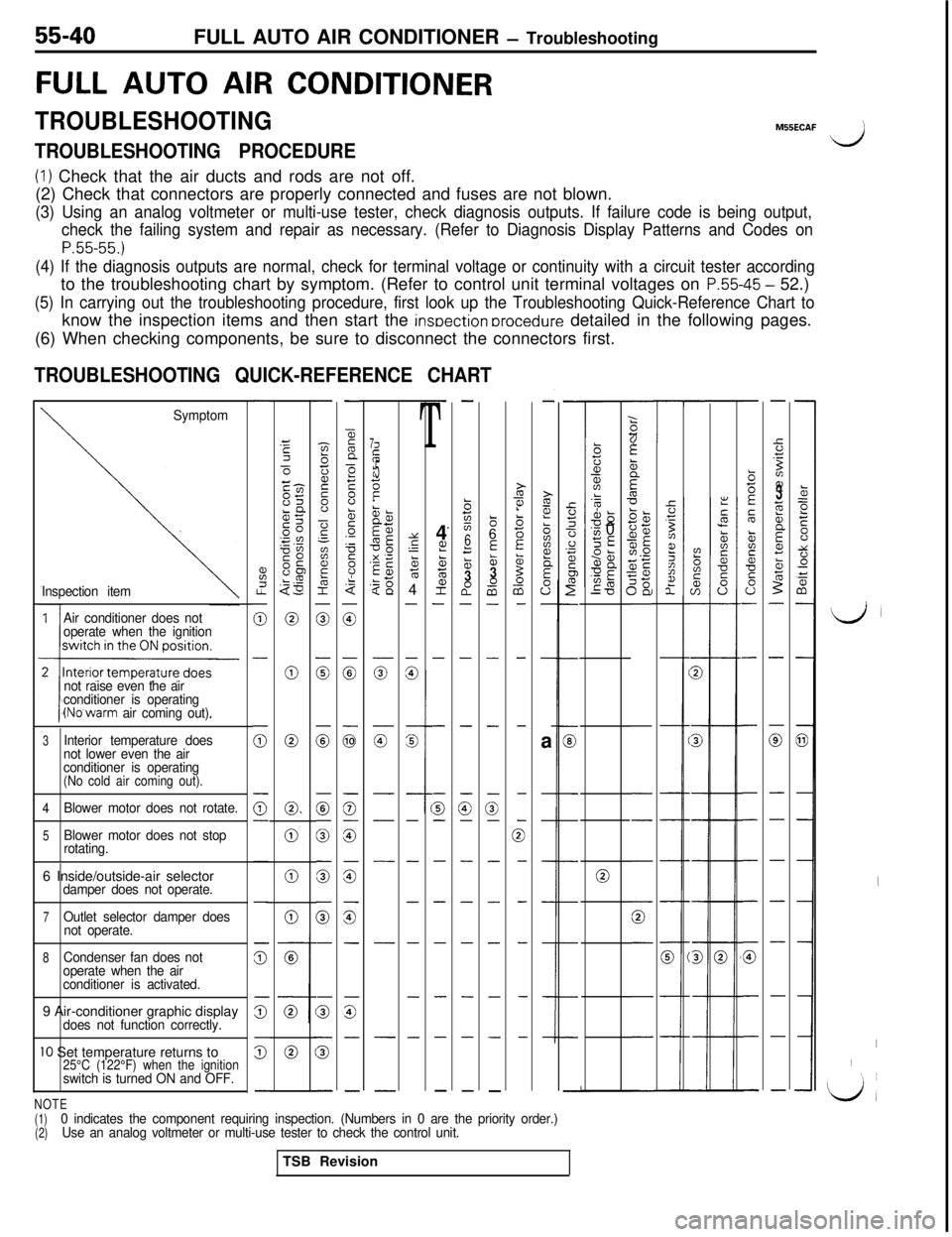
(1) Check that the air ducts and rods are not off.
(2) Check that connectors are properly connected and fuses are not blown.
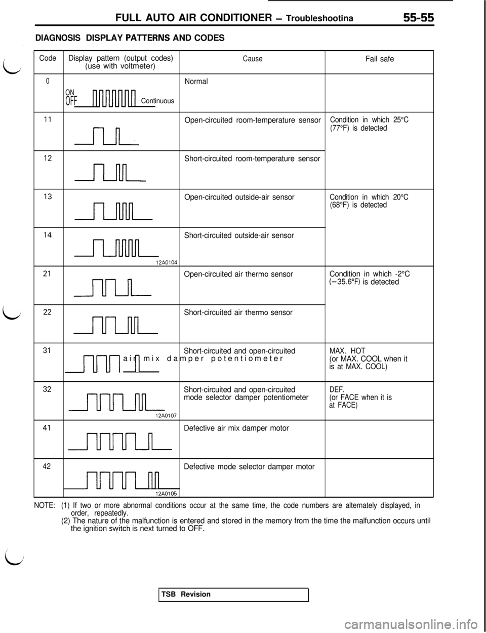
(3) Using an analog voltmeter or multi-use tester, check diagnosis outputs. If failure code is being output,
check the failing system and repair as necessary. (Refer to Diagnosis Display Patterns and Codes on
P.55-55.)
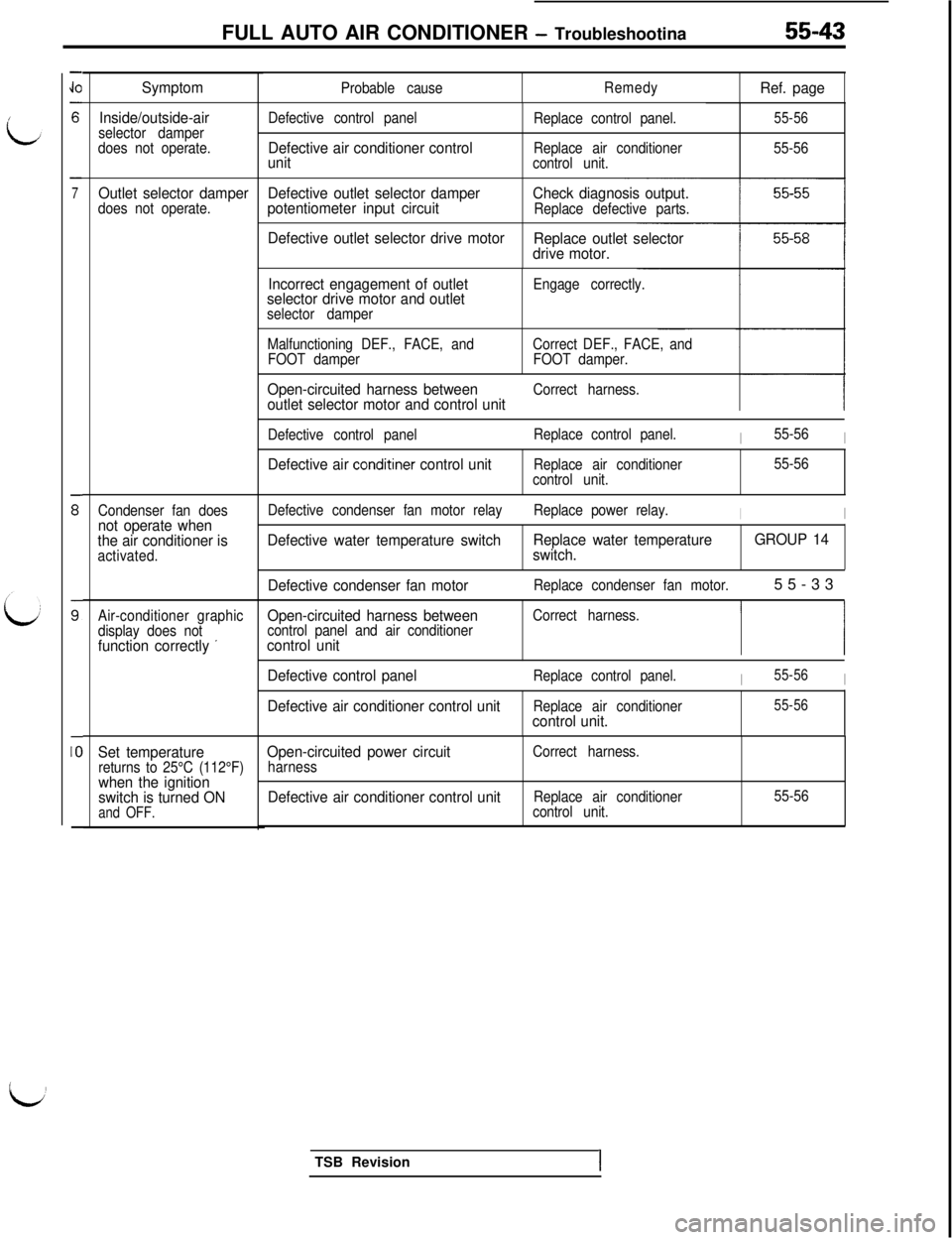
(4) If the diagnosis outputs are normal, check for terminal voltage or continuity with a circuit tester accordingto the troubleshooting chart by symptom. (Refer to control unit terminal voltages on
P.55-45 - 52.)
(5) In carrying out the troubleshooting procedure, first look up the Troubleshooting Quick-Reference Chart toknow the inspection items and then start the
insoection orocedure detailed in the following pages.
(6) When checking components, be sure to disconnect the connectors first.
TROUBLESHOOTING QUICK-REFERENCE CHART
-
%I.?
0
-
(i;
0-
-
-
z
s
5
-
z3Ec-l-cm85LQgc .”0”SO0s“E$3
0
0
0
0.
0
0
0
-
-zbij2s”
-?‘-
aF&I
0
0
0
0
0
0
G
-
s
5
-
-
55n
>F8b5.-
F
8.$
0
:
G
0
G
is
z
-
G-
-
-
-
T4
L??ctE;
2-
-
-
G-
-
-
-
-
-
-.
-
b725
6
f53a0-
-
-
G-
-
-
-
-
-
-
86
E&3-0a-
-
-
-
3-
-
-
-
-
-
-
-
i?i?!
biiz?
E
0”-
-a
-
-
-
-
-
-
-
GE
21z6:1D-
-
-
-
-
0
-
-
-
-
-
;(if
zzit
5
5‘dTC
T-
-:
2
2
::ii3z;
2%;sjE1.0
;g5E
-
:
,,
,
1
-
-
-
-
0
-
-
-
-
-
k=eE00
t:0+i
-
-
a
-
-
-
-
-
-
-
-
b5E
5
&is*
s0-
-
-
-
-
-
-
G
-
-
-
-
5.T
Bz??3;i;b
Ecz
5-
-
0
-
-
-
-
-
-
-
-
1
225cn-
s
s----
s---
Symptom
Inspection item
7i;if
II:.?t.!
1E5z
iT-a,?z
5g< 13;$
zg
z
G-
-
-
-
-
-
-
.k?alL-0s
‘v, 0SE95anUE
ma‘0Y
s‘-5764
-
-
%G
-
-
-
-
-
-
-
Air conditioner does not
operate when the ignition
not raise even the air
conditioner is operating
(No’warm air coming out).
LJ
I
I~
‘L/,
3Interior temperature does
not lower even the air
conditioner is operating
(No cold air coming out).
4
Blower motor does not rotate.
5Blower motor does not stop
rotating.
06 Inside/outside-air selectordamper does not operate.
7Outlet selector damper does
not operate.
8Condenser fan does not
operate when the air
conditioner is activated.9 Air-conditioner graphic display
does not function correctly.
IO Set temperature returns to25°C (122°F) when the ignitionswitch is turned ON and OFF.
NOTE(1)
(2)0 indicates the component requiring inspection. (Numbers in 0 are the priority order.)
Use an analog voltmeter or multi-use tester to check the control unit.TSB Revision
Page 1125 of 1146
FULL AUTO AIR CONDITIONER - Troubleshootina55-43
-
JO
6
-
7
s
s
-
IO
-
Symptom
Inside/outside-air
selector damper
does not operate.
Outlet selector damperDefective outlet selector damperdoes not operate.potentiometer input circuit
Condenser fan doesnot operate when
the air conditioner is
activated.
Air-conditioner graphic
Open-circuited harness betweenCorrect harness.
display does notcontrol panel and air conditioner
function correctly ’control unitI I
Set temperaturereturns to 25°C (112°F)when the ignition
switch is turned ON
and OFF.
Probable causeRemedyRef. page
Defective control panel
Defective air conditioner control
unit
Replace control panel.
Replace air conditioner
control unit.55-56
55-56
Check diagnosis output.Replace defective parts.
Defective outlet selector drive motor
Replace outlet selector
drive motor.
Incorrect engagement of outlet
selector drive motor and outlet
selector damperEngage correctly.
Malfunctioning DEF., FACE, andCorrect DEF., FACE, and
FOOT damperFOOT damper.
Open-circuited harness betweenCorrect harness.outlet selector motor and control unit
Defective control panelReplace control panel.I55-56I
Defective air conditiner control unitReplace air conditioner
control unit.55-56
Defective condenser fan motor relayReplace power relay.
II
Defective water temperature switchReplace water temperature
switch.GROUP 14
Defective condenser fan motor
Replace condenser fan motor.55-33
Defective control panelReplace control panel.I55-56I
Defective air conditioner control unitReplace air conditionercontrol unit.
55-56
Open-circuited power circuitharnessCorrect harness.
Defective air conditioner control unitReplace air conditioner
control unit.55-56TSB Revision
I
Page 1137 of 1146
FULL AUTO AIR CONDITIONER - Troubleshootina55-55
DIAGNOSISDISPLAY PAlTERNS AND CODES
/
L
ii
CodeDisplay pattern (output codes)CauseFail safe(use with voltmeter)
0Normal
ON
OFFContinuous
I1 n
Open-circuited room-temperature sensorCondition in which 25°C
(77°F) is detected
I2 n
Short-circuited room-temperature sensor
I3 n
Open-circuited outside-air sensorCondition in which 20°C
(68°F) is detected
I4 n
Short-circuited outside-air sensor
12A0104
21 -,llJlL
Open-circuited air therm0 sensorCondition in which -2°C(-35.6”F) is detected
22 nn
Short-circuited air therm0 sensor
31 J-[-u1 1Short-circuited and open-circuitedair mix damper potentiometerMAX. HOT(or MAX. COOL when itis at MAX. COOL)
32 nnn
Short-circuited and open-circuitedDEF.mode selector damper potentiometer(or FACE when it isat FACE)
12A0107
41, nnnn
Defective air mix damper motor
42Defective mode selector damper motor
1uuuI nn12A0105
NOTE:(1) If two or more abnormal conditions occur at the same time, the code numbers are alternately displayed, in
order, repeatedly.
(2) The nature of the malfunction is entered and stored in the memory from the time the malfunction occurs until
the ignition switch is next turned to OFF.TSB Revision