Page 1119 of 1146
HEATERS AND MANUAL AIR CONDITIONER -Ventilators (Instrument Panel) 55-37
/ 2OFOO321
SERVICE POINTS OF REMOVALM55YBAH
15. REMOVAL OF DEFROSTER GARNISHES
Using the trim stick, remove the defroster garnishes fromthe instrument panel.
16. REMOVAL OF PHOTO SENSORUsing the trim stick, remove the photo sensor from the
defroster garnish.
17. REMOVAL OF CENTER AIR OUTLET ASSEMBLY
Disengaging the clips (2 positions) of the center air-outlet
assembly with a flat tip screwdriver, remove the center airoutlet assembly with the trim stick.
1 TSB Revision
Page 1121 of 1146
Pre-removal and Post-installation Operationl Draining and Refilling of Engine Coolant(Refer to GROUP 00 - Maintenance Service.)
1. Engine coolant temperature switchHEATERS AND MANUAL AIR CONDITIONER
- Z!&E%Ltch55-39
ENGINE COOLANT TEMPERATURE SWITCH
M55xA- -
L
REMOVAL AND INSTALLATIONSealant: 3M Nut Locking Part No.
4171 or equivalent
BQQQQQ20A0199INSPECTION
MSSXCAAENGINE COOLANT TEMPERATURE SWITCH
(ALWAYS-
CLOSED TYPE CHECK)
(1) Immerse the engine coolant temperature switch in oil and
heat by a gas stove or similar method so as to increase the
oil temperature.(2) Check to be sure that the engine coolant temperature
switch is switched OFF when the oil temperature reaches
the standard value.Standard value: 112
- 118°C (233 - 244°F)
CautionUse engine oil for this test; stir it well while heating,
and do not heat more than necessary.
1 TSB Revision
Page 1136 of 1146

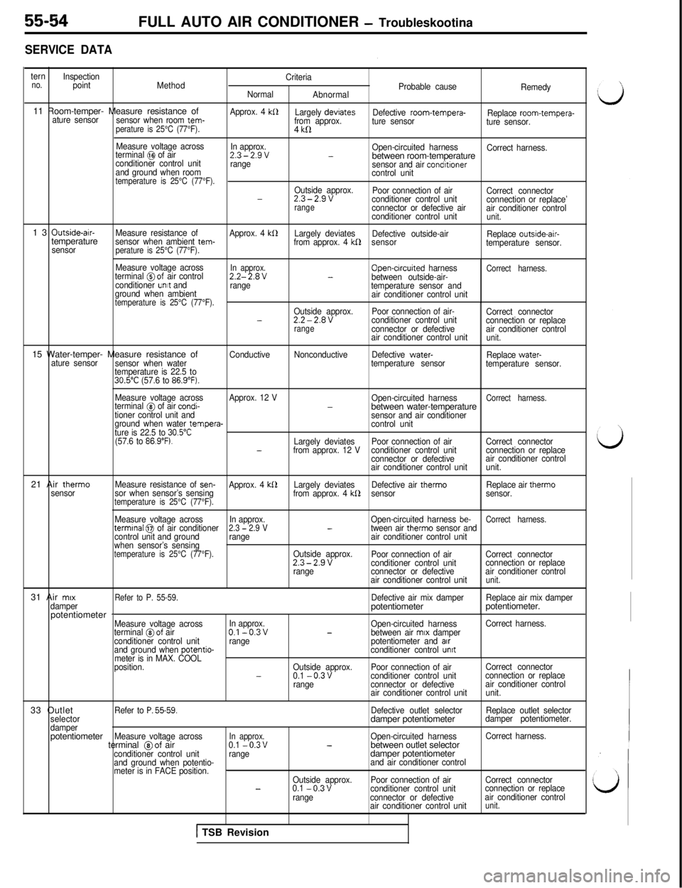
SERVICE DATA
ternno.Inspection
point
MethodCriteria
Probable cause
Normal
AbnormalRemedy11 Room-temper- Measure resistance of
sensor when room tem- ature sensorperature is 25°C (77°F).
Approx. 4 kS1Largely devrates
from approx.Defective room-tempera-
Replace room-tempera-
ture sensor
ture sensor.4
kll
Measure voltage across
In approx.
terminal @I of airOpen-circuited harness
Correct harness.2.3-2.9v-conditioner control unitbetween room-temperaturerange
sensor and air condrtionerand ground when room
control unittemperature is 25°C (77°F).Outside approx.
Poor connection of air
Correct connector-2.3-2.9vconditioner control unit
connection or replace’rangeconnector or defective air
air conditioner control
conditioner control unitunit.13
Outside-air-
Measure resistance of
Approx. 4 kllLargely deviates
Defective outside-air
Replace outside-air-temperaturesensor when ambient tem-
from approx. 4 kf2sensor
temperature sensor.
sensorperature is 25°C (77°F).
Measure voltage acrossIn approx.terminal @of air controlOpen-crrcuited harnessCorrect harness.2.2-2.8V-between outside-air-
conditioner unrt and
range
temperature sensor and
ground when ambient
air conditioner control unit
temperature is 25°C (77°F).Outside approx.Poor connection of air-
Correct connector-2.2-2.8Vconditioner control unit
connection or replacerangeconnector or defectiveair conditioner control
air conditioner control unitunit.15 Water-temper- Measure resistance of
ConductiveNonconductiveDefective water-
Replace water-
ature sensor
sensor when watertemperature sensor
temperature sensor.
temperature is 22.5 to
30.5”C (57.6 to 86.9”F).21 Air therm0
sensorMeasure voltage acrossApprox. 12 V
Open-circuited harness
Correct harness.terminal @ of air condi--between water-temperaturetioner control unit and
sensor and air conditioner
ground when water tempera-
control unit
ture is 22.5 to 30.5”C(57.6 to 86.9”F).Largely deviatesPoor connection of airCorrect connector-from approx. 12 Vconditioner control unitconnection or replace
connector or defectiveair conditioner control
air conditioner control unitunit.
Measure resistance of
sen-Approx. 4 kS2Largely deviatesDefective air therm0Replace air therm0
sor when sensor’s sensing
from approx. 4 kb2sensorsensor.temperature is 25°C (77°F).
Measure voltage acrossIn approx.Open-circuited harness be-Correct harness.termrnal 0 of air conditioner2.3 - 2.9 V-tween air therm0 sensor and
control unit and groundrangeair conditioner control unit
when sensor’s sensing
temperature is 25°C (77°F).Outside approx.
Poor connection of airCorrect connector2.3-2.9vconditioner control unitconnection or replace
rangeconnector or defectiveair conditioner control
air conditioner control unit
unit.31 Air
mrx
Refer to P. 55-59.Defective air mix damperReplace air mix damper
damperpotentiometerpotentiometer.
potentiometer
-Measure voltage acrossIn approx.
Open-circuited harnessCorrect harness.
terminal @of airO.l-0.3v-between air mrx damper
conditioner control unitrangepotentiometer and arrand ground when potentio-conditioner control unrtmeter is in MAX. COOL
position.Outside approx.Poor connection of airCorrect connector
-0.1 -0.3vconditioner control unitconnection or replace
rangeconnector or defectiveair conditioner control
air conditioner control unitunit.33 Outlet
Refer to P. 55-59.Defective outlet selectorReplace outlet selector
selectordamper potentiometerdamper potentiometer.
damperpotentiometer
Measure voltage acrossIn approx.Open-circuited harnessCorrect harness.terminal @of air0.1 -0.3v-between outlet selectorconditioner control unitrangedamper potentiometerand ground when potentio-and air conditioner control
meter is in FACE position._Outside approx.Poor connection of airCorrect connector-0.1 -0.3vconditioner control unitconnection or replace
rangeconnector or defectiveair conditioner control
air conditioner control unit
unit.FULL AUTO AIR CONDITIONER
- Troubleskootina
1 TSB Revision
Page 1138 of 1146
55-56FULL AUTO AIR CONDITIONERSafety Precautions I Service Adjustment Procedures I- Air Conditioner Control Panel, Air Condiiioner Control Unit
SAFETY PRECAUTIONSSame as those given in HEATERS AND MANUAL AIR CONDITIONER. (Refer to
P.55-9.)
SERVICE ADJUSTMENT PROCEDURESSame as those given in HEATERS AND MANUAL AIR CONDITIONER. (Refer to
P.55-10.)
M55FEAVI
AIR CONDITIONER CONTROL PANEL, AIR CONDITIONER CONTROL
UNIT
REMOVAL AND INSTALLATIONhl!XGA-E
2OFOO69Removal steps
*I)1. Center air outlet assembly
2. Air conditioner control panel
3. Air conditioner control unit
SERVICE POINT OF REMOVALMWSGBAMZ1.
.REMOVAL OF CENTER AIR OUTLET ASSEMBLY
Disengaging the clips (2 positions) of the center air outlet
assembly with a flat tip screwdriver, remove the center
airoutlet assembly with a plastic trim stick.
I
ij!
Page 1140 of 1146

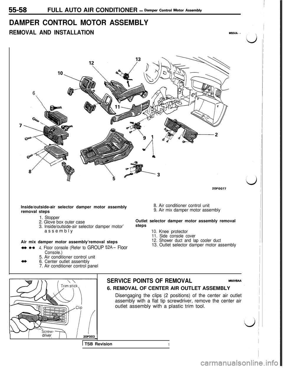
55-58FULL AUTO AIR CONDITIONER - Damper Control Motor As=W
DAMPER CONTROL MOTOR ASSEMBLY
REMOVAL AND INSTALLATIONM55VA- -
6
\
2OFOO77Inside/outside-air selector damper motor assembly
removal steps
8. Air conditioner control unit
9. Air mix damper motor assembly
1. Stopper
2. Glove box outer case
3. Inside/outside-air selector damper motor’assemblyOutlet selector damper motor assembly removal
steps
IO. Knee protector11. Side console coverAir mix damper motor assembly‘removal steps
w *a4. Floor console (Refer to GROUP 52A- Floor
Console.)5. Air conditioner control unita*6. Center outlet assembly
7. Air conditioner control panel
12. Shower duct and lap cooler duct13. Outlet selector damper motor assembly
IIdriver, ,/ 20;003--t
1 TSB Revision
SERVICE POINTS OF REMOVALM55vaAA6. REMOVAL OF CENTER AIR OUTLET ASSEMBLY
Disengaging the clips (2 positions) of the center air outlet
assembly with a flat tip screwdriver, remove the center airoutlet assembly with a plastic trim tool.
1
Page 1142 of 1146
55-60
SENSORSFULL AUTO AIR CONDITIONER
- Sensors
REMOVAL AND INSTALLATIONM550A- _
4*1. Passenger compartment temperature sen-sor2OFOO63
Outside air sensor removal steps
2. Stopper
3. Glove box outer case
4. Photo sensor connector connection
5. Photo sensorWater temperature sensor removal steps
2. StopperI3: F/it; box outer case assembly
7. Water temperature sensorOutside-air-temperature sensor removal steps
2. Stopper
3. Glove box outer case assembly
8. Outside-air-temperature sensor
82OFOO75
-
Passenger compartment
temperature sensor
SERVICE POINTS OF REMOVALM5506AE
1. REMOVAL OF PASSENGER COMPARTMENT TEMPER-
ATURE SENSOR
2OPO164LlTSB Revision
Using the trim stick, remove the passenger compartmenttemperature sensor from the headlining.
I~’
I
d
I
d
Page 1144 of 1146

55-62FULL AUTO AIR CONDITIONER
ICompressor. Condenser, Condenser Fan Motor, Refrigerant
- Line and Engine Coolant Temperature Switch / Other Parts
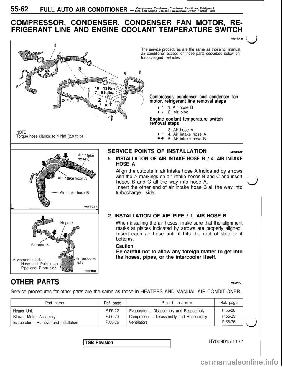
COMPRESSOR, CONDENSER, CONDENSER FAN MOTOR, RE-
FRIGERANT LINE AND ENGINE COOLANT TEMPERATURE SWITCH
M55TA-B4
The service procedures are the same as those for manual
air conditioner except for those parts described below on
turbocharged vehicles.5
Compressor, condenser and condenser fanmotor, refrigerant line removal steps
l *I. Air hose Bl +2. Air pipe
ii
Engine coolant temperature switch
removal steps
NOTETorque hose clamps to 4 Nm (2.9 ftlbs.).3. Air hose Al *4. Air intake hose A*a5. Air intake hose B
L
Air intake hose B
OSFOO23
Align7ment marks
Hose end: Paint mar
Pipe end:
Protrusron
OTHER PARTS
SERVICE POINTS OF INSTALLATIONM55iDAF
5.INSTALLATION OF AIR INTAKE HOSE B / 4. AIR INTAKE
HOSE AAlign the cutouts in air intake hose A indicated by arrows
with the n markings on air intake hoses B and C and inserthoses B and C all the way into hose A.
Insert the other end of air intake hose B all the way into
turbocharger side.2. INSTALLATION OF AIR PIPE
/ 1. AIR HOSE B
When installing the air hoses, make sure that the alignment
marks at places indicated by arrows are properly aligned.Insert each air hose until it hits the root of step or it
bottoms.
CautionBe careful not to allow any foreign matter to get into
the hoses, pipes, or the intercooler itself.M55WA-
-
Service procedures for other parts are the same as those in HEATERS AND MANUAL AIR CONDITIONER.
Part name
Ref. page
Heater Unit
P.55-22
Blower Motor AssemblyP.55-23
Evaporator - Removal and InstallationP.55-25Part name
Evaporator - Disassembly and Reassembly
Compressor
- Disassembly and Reassembly
VentilatorsRef. page
P.55-26
P.55-29
1 TSB RevisionHY009015-1132