1991 MITSUBISHI 3000GT low oil pressure
[x] Cancel search: low oil pressurePage 864 of 1146

37B44-WHEEL STEERING SYSTEM (4WS) -Service Adjustment ProceduresSERVICE ADJUSTMENT PROCEDURES
M37FKAH
BLEEDING,LJ(1) Bleed air from power steering system (Refer to GROUP
37A
- Service Adjustment Procedures.)
(2) Lift up the vehicle.
(3) Start the engine and let it idle.
(4) Loosen the bleeder screw on the left side of the control
valve and set the special tool to the bleeder screw.
(5) Turn the steering wheel all the way to the left, immediately
returning it half way back.
At this time confirm that air is discharged with the fluid.
(6) Repeat step (5) two or three times, then check to ensure
that all air has been bled from the system.
(7) Repeat steps (4) through (6) for the right side bleeder
sc,rew, turning the steering wheel to the right this time.
(8) Loosen the power cylinder bleeder screw and set the
special tool to the bleeder screw.
Caution
Loosen the bleeder screw about 30 to 45 degrees, andsecure it with the special tool (rotation prevention
metal fixtures) so as not to be loosened more.
(9) Start the engine, running the vehicle at an indicated speed
I/l1Iof about 70-80 km/h (43-50 mph) to circulate the fluid.
-13FOO13
Caution
When replenishing the fluid, take special care as all fourIwheels will be rotating.
Fluid level difference within
5 mm (.20 in.)
While
engineWhile engine isIS runningstopped13lJO13~(lO)Maintain an indicated speed of about 30-40 km/h (19-25
mph), turning the steering wheel all the way to both left and
right.
When the wheel is steered all the way in either direction,
pressure will rise and air will circulate inside the tube
(special tool). Check to ensure that this air is discharged into
the oil reservoir.
(1 l)Repeat step (10) several times until that all air in the system
has been bled.
(12)Ensure that the difference in the fluid levels when the
engine is running and when it is stopped are within 5 mm(.20 in.).
If the difference exceeds 5 mm
(.20 in.), there is still air in
the system and it must be bled again.
Caution
If air has not been completely bled from the system, the
pump will make a humming sound or an unusual noise ,,
will come from the flow control valve; this also
dcontributes to shortened pump life.
TSB Revision
Page 865 of 1146

4-WHEEL STEERING SYSTEM (4WS) -Service Adjustment Procedures37B-5
Rubber hose
13FOOl
Graduated cylinder13FOOllFUNCTION CHECK
_M37FWAA
(1) Raise the vehicle so that all four wheels may turn freely.
(2) Start the engine, running the vehicle at an indicated speed
of about 80
km/h (50 mph).
(3) Turn the steering wheel all the way to left and right and turn
it swiftly, checking to ensure that the rear wheels steer to
the same directions as the front wheels.
REAR OIL PUMP DISCHARGE FLOW VOLUME
CHECKM37FLBA
(1) Disconnect the pressure hose from the rear oil pump and
install the special tool with a rubber hose.
(2) Place the other end of the rubber hose in a container which
permits measurement of flow rate (2-liter graduated cylin-
der).(3) Start the engine. Increase speed slowly, then hold the
indicated speed of 50 km/h (31 mph), measuring discharge
flow volume for 30 seconds.
Caution
While performing this work, continuously add fluid intothe oil reservoir.
Standard value: Approximately
1.0 liter (1.06 qts.)
(4) If the discharge flow volume is extremely high or low, the
rear oil pump should be replaced.
BALL JOINT ROTATION STARTING TORQUE
CHECKM37FECA
(1) Holding the power cylinder tie rod with a spanner, discon-
nect the tie rod and trailing arm.
(2) After swinging the ball joint stud several times, install the
stud nut, then measure the ball joint rotation starting torque
with the special tool.
Standard value: 0.5 Nm (4
in.lbs.) or less
(3) If the rotation starting torque exceeds the standard value,
replace the tie rod end.
(4) If the rotation starting torque is less than the standard
value, check that the ball joint is not loose and operates
smoothly. If not, it may be reused.
TSB Revision
Page 866 of 1146

37B-64-WHEEL STEERING SYSTEM (4WS) - Power CylinderPOWER CYLINDER
REMOVAL AND INSTALLATION
M37S&~I
l Cleaning of Pipings with Steam
l Removal of Main Muffler Assembly(Referto GROUP 15- Exhaust Pipe and Muffler.)
Ilo-130Nm
l Installation of Main Muffler Assembly
l Refilling and Bleeding of Power Steering System
(Refer to GROUP 37A-Service Adjustment
\78 Nml;O- 130 Nm
56
ft.lbs.80 - 94 ft.lbs.
Procedures.)l Bleeding of 4WS System
(Refer to P.37B-4.)l Checking of 4WS System for Operation
(Refer to P.37B-5.)‘0 Checking of Wheel Alignment
(Refer to GROUP 34 -Service Adiustment
1 Procedures.)
f @, ’ i%,s. yf ,30Nm,
78 NmIIO-130Nm80 -94 ft.lbs.56 ft.lbs.
80 - 94 ft.lbs.Removal steps
1. Rear shock absorber lower mounting bolt
2. Crossmember bracket
a*3. Crossmember mounting nut
(on differential side)
4. Pressure tube
(RL)5. O-ring
6. Pressure tube (RR)
7. O-ring
8. Oil line clamp bolt
4*9. Tie rod end nut
l * 10. Power cylinder installation bolt
l * 11. Power cylinder
Fluid line flared nut
15 Nm
11 ft.lbs.14FO38
‘dTSB Revision
Page 1091 of 1146
HEATERS AND MANUAL AIR CONDITIONER - safety Pre=utm55-9
SAFETY PRECAUTIONSR-12 refrigerant is a chlorofluoro-carbon
(CFC) that
can contribute to the depletion of the ozone layer in
the upper atmosphere.
Ozone filters out harmful radiation from the sun.
To assist in protecting the ozone layer, Mitsubishi
Motor Sales of America recommends that a R-12
refrigerant recycling device that meets SAE stan-
dard
J1991 be used.
Contact an automotive service equipment supplier
for refrigerant recycling equipment that is available
in your area.
The refrigerant used in all air conditioner is R-l 2. It is
transparent and colorless in both the liquid and
vapor state. Since it has a boiling point of
-29.8”C(-21.7”F), at atmospheric pressure, it will be a vapor
at all normal temperatures and pressures. The vapor
is heavier than air, non-flammable, and nonexplo-
sive. It is nonpoisonous except when it is in direct
contact with open flame. It is noncorrosive except
when combined with water. The following precau-
tions must be observed when handling R-12.
CautionWear safety goggles when servicing the refri-
geration system.R-12 evaporates so rapidly at normal atmospheric
pressures and temperatures that it tends to freeze
anything it contacts. For this reason, extreme care
must be taken to prevent any liquid refrigerant from
contacting the skin and especially the eyes. Always
wear safety goggles when servicing the refrigera-
tion part of the air conditioning system. Keep a
bottle of sterile mineral oil handy when working on
the refrigeration system. Should any liquid re-
frigerant get into the eyes, use a few drops of
mineral oil to wash them out. R-12 is rapidly
absorbed by the oil. Next splash the eyes with
plenty of cold water. Call your doctor immediately
even though irritation has ceased after treatment.
CautionDo not heat R-12 above 52°C
(125.6”F).
M55PAAFIn most instances, moderate heat is required to
bring the pressure of the refrigerant in its container
above the pressure of the system when charging or
adding refrigerant. A bucket or large pan of hot
water not over 52°C
(125.6”F) is all the heat required
for this purpose. Do not heat the refrigerant contain-
er with a blow torch or any other means that would
raise temperature and pressure above this tempera-
ture. Do not weld or steam clean on or near the
system components or refrigerant lines.
Caution
Keep R-12 containers upright when charging the
system.When metering R-12 into the refrigeration system,
keep the supply tank or cans in an upright position. If
the refrigerant container is on its side or upside
down, liquid refrigerant will enter the system and
damage the compressor.
CautionAlways work in a well-ventilated room.
Good ventilation is vital in the working area.
Although R-12 vapor is normally nonpoisonous,
contact with an open flame can cause the vapor to
become very poisonous. A poisonous gas is pro-
duced when using the flame-type leak detector.
Avoid inhaling the fumes from the leak detector.
CautionDo not allow liquid refrigerant to touch bright
metal.Refrigerant will tarnish bright metal and chrome
surfaces, and in combination with moisture can
severely corrode all metal surfaces.
1 TSB Revision
Page 1096 of 1146
CautionRefrigerantR-l 2iAdaptorNever use the high pressure side as this may cause
/valve
refrigerant to flow back, using rupture of the servicecan.(7) Start the engine. Charge valvergmg hose
55-14 HEATERS AND MANUAL AIR CONDITIONER - Service Adjustment procedures
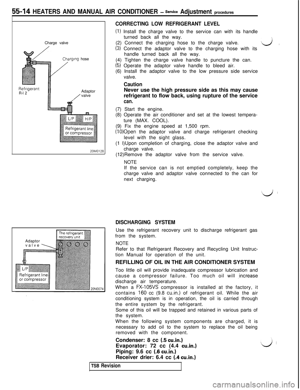
CORRECTING LOW REFRIGERANT LEVEL
(I) Install the charge valve to the service can with its handle
turned back all the way.
(2) Connect the charging hose to the charge valve.
(3) Connect the adaptor valve to the charging hose with itsL&lhandle turned back all the way.
(4) Tighten the charge valve handle to puncture the can.
(5) Operate the adaptor valve handle to bleed air.
(6) Install the adaptor valve to the low pressure side service
valve.
(8) Operate the air conditioner and set at the lowest tempera-
ture (MAX. COOL).
(9) Fix the engine speed at 1,500 rpm.
(10)Open the adaptor valve and charge refrigerant checking
level with the sight glass.
(1 l)Upon completion of charging, close the adaptor valve and
20M0128charge valve.
(12)Remove the adaptor valve from the service valve.
NOTEIf the service can is not emptied completely, keep the
charge valve and adaptor valve connected to the can for
next charging.
Adaptor
valve
\
DISCHARGING SYSTEMUse the refrigerant recovery unit to discharge refrigerant gas
from the system.
NOTERefer to that Refrigerant Recovery and Recycling Unit Instruc-
tion Manual for operation of the unit.
REFILLING OF OIL IN THE AIR CONDITIONER SYSTEM
Too little oil will provide inadequate compressor lubrication and
cause a compressor failure. Too much oil will ,increase
discharge air temperature.
When a
FX-105VS compressor is installed at the factory, it
contains
160 cc (9.8 cu.in.) of refrigerant oil. While the air
conditioning system is in operation, the oil is carried through
the entire system by the refrigerant.
Some of this oil will be trapped and retained in various parts of
the system.
When the following system components are charged, it is
necessary to add oil to the system to replace the oil being
removed with the component.
Condenser: 8 cc
(5 cu.in.)Evaporator: 72 cc (4.4
cu.in.)Piping: 9.6 cc
(6 cu.in.)Receiver drier: 6.4 cc
(.4 cu.in.)
TSB Revision
Page 1099 of 1146
HEATERS AND MANUAL AIR CbNDlTlONER -Service Adjustment Procedures 55 17
ADJUSTMENT PROCEDURES(1) Select a quiet area for testing. Duplicate conditions as much
as possible. Switch compressor on and off several times to
clearly identify compressor noise.
To duplicate high ambient conditions (high head pressure),
restrict air flow through condenser. Install manifold gauge
set to make sure discharge pressure doesn’t exceed 2,070
kPa (300 psi).
(2) Tighten all compressor mounting bolts, clutch mounting
bolt, and compressor drive belt. Check to assure clutch coil
is tight (no rotation or wobble).
(3) Check refrigerant hoses for rubbing or interference that can
cause unusual noises.
(4) Check refrigerant charge. (See “Charging System”.)
(5) Recheck compressor noise as in Step 1.
(6) If noise still exists, loosen compressor mounting bolts and
retorque. Repeat Step 1.
(7) If noise continues, replace compressor and repeat Step 1.
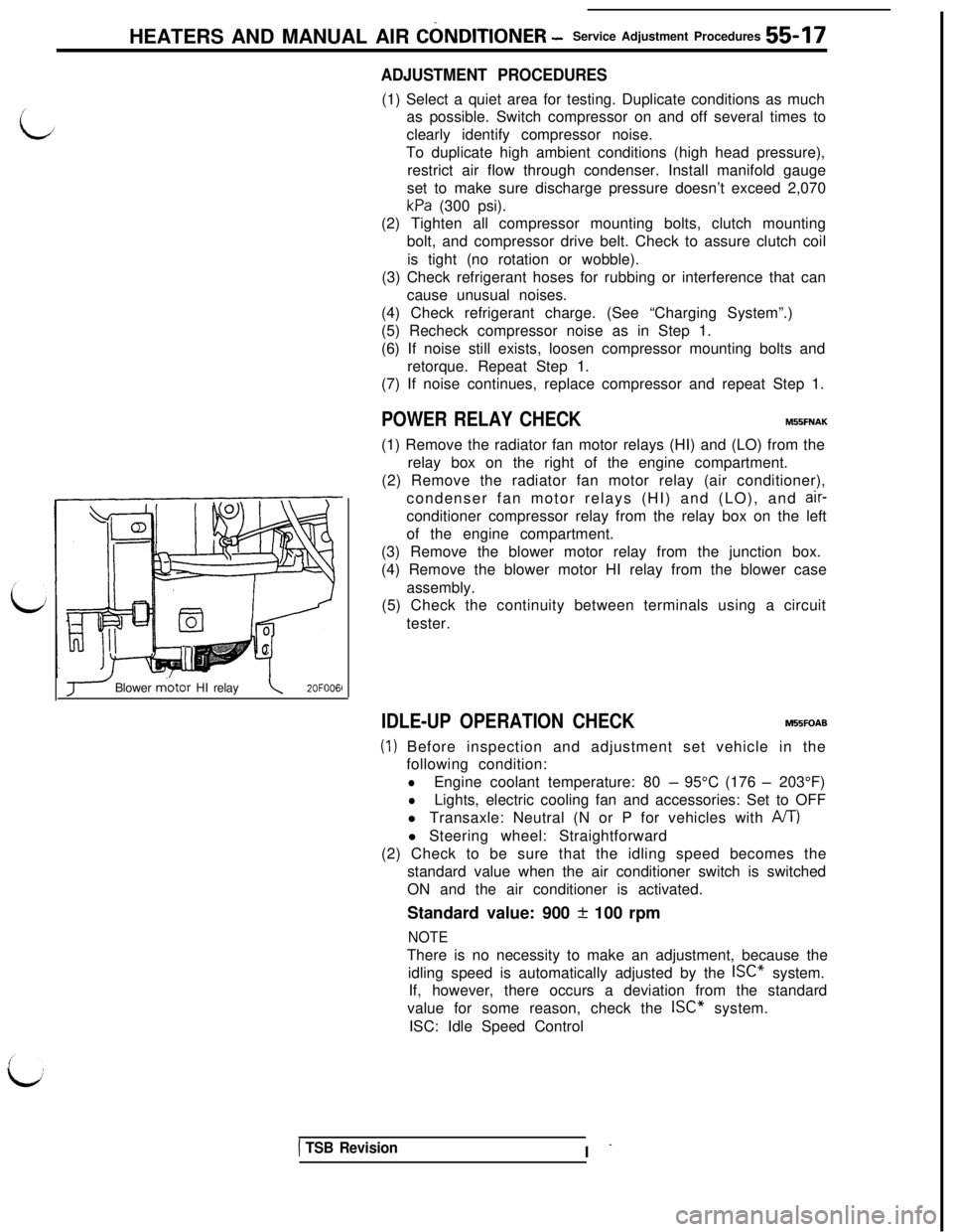
POWER RELAY CHECKMBBFNAK(1) Remove the radiator fan motor relays (HI) and (LO) from the
relay box on the right of the engine compartment.
(2) Remove the radiator fan motor relay (air conditioner),
condenser fan motor relays (HI) and (LO), and
air-conditioner compressor relay from the relay box on the left
of the engine compartment.
(3) Remove the blower motor relay from the junction box.
(4) Remove the blower motor HI relay from the blower case
assembly.
(5) Check the continuity between terminals using a circuit
tester.
J Blower m.otor HI relay\2OFOO6l
IDLE-UP OPERATION CHECKM55FOAB
(1) Before inspection and adjustment set vehicle in the
following condition:
lEngine coolant temperature: 80 - 95°C (176 - 203°F)
lLights, electric cooling fan and accessories: Set to OFF
l Transaxle: Neutral (N or P for vehicles with
A/T)l Steering wheel: Straightforward
(2) Check to be sure that the idling speed becomes the
standard value when the air conditioner switch is switched
ON and the air conditioner is activated.
Standard value: 900
+ 100 rpm
NOTEThere is no necessity to make an adjustment, because the
idling speed is automatically adjusted by the ISC” system.
If, however, there occurs a deviation from the standard
value for some reason, check the ISC” system.
ISC: Idle Speed Control
1 TSB RevisionI -
Page 1112 of 1146
HEATERS AND MANUAL AIR CONDITIONER - Compressor
Spring
Valve
ompressor
2OPO286~
SERVICE POINT OF DISASSEMBLYMSlSFAE3. REMOVAL OF NUT
Use the special tool to loosen the nut,
INSPECTIONM55SGABl Check the surface of the armature for scoring or bluing.
l Check the surface of the rotor for scoring or bluing.
l Check the sealing surfaces for cracks, scratches and
deformation.
0Check the front housing for cracks or scoring on the sealing
surfaces.l Check the compressor shaft for scoring.
J
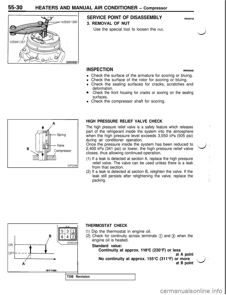
HIGH PRESSURE RELIEF VALVE CHECK
The high pressure relief valve is a safety feature which releasesI
part of the refrigerant inside the system into the atmospherewhen the high pressure level exceeds 3,550
kPa (505 psi)
during air conditioner operation.Once the pressure inside the system has been reduced to
2,400
kPa (341 psi) or lower, the high pressure relief valveL&Jcloses, thus allowing continued operation.
(1) If a leak is detected at section A, replace the high pressure
relief valve. The valve can be used unless there is a leak(from that section.
(2) If a leak is detected at section B, retighten the valve. If the
leak still persists after retightening the valve, replace the
packing.
THERMOSTAT CHECK
(1) Dip the thermostat in engine oil.
(2) Check for continuity across terminals @ and @ when theengine oil is heated.
Standard value:Continuity at approx.
110°C (230°F) or less
at A pointNo continuity at approx. 155°C (311°F) or more
,I
at B pointII;TSB Revision
Page 1113 of 1146
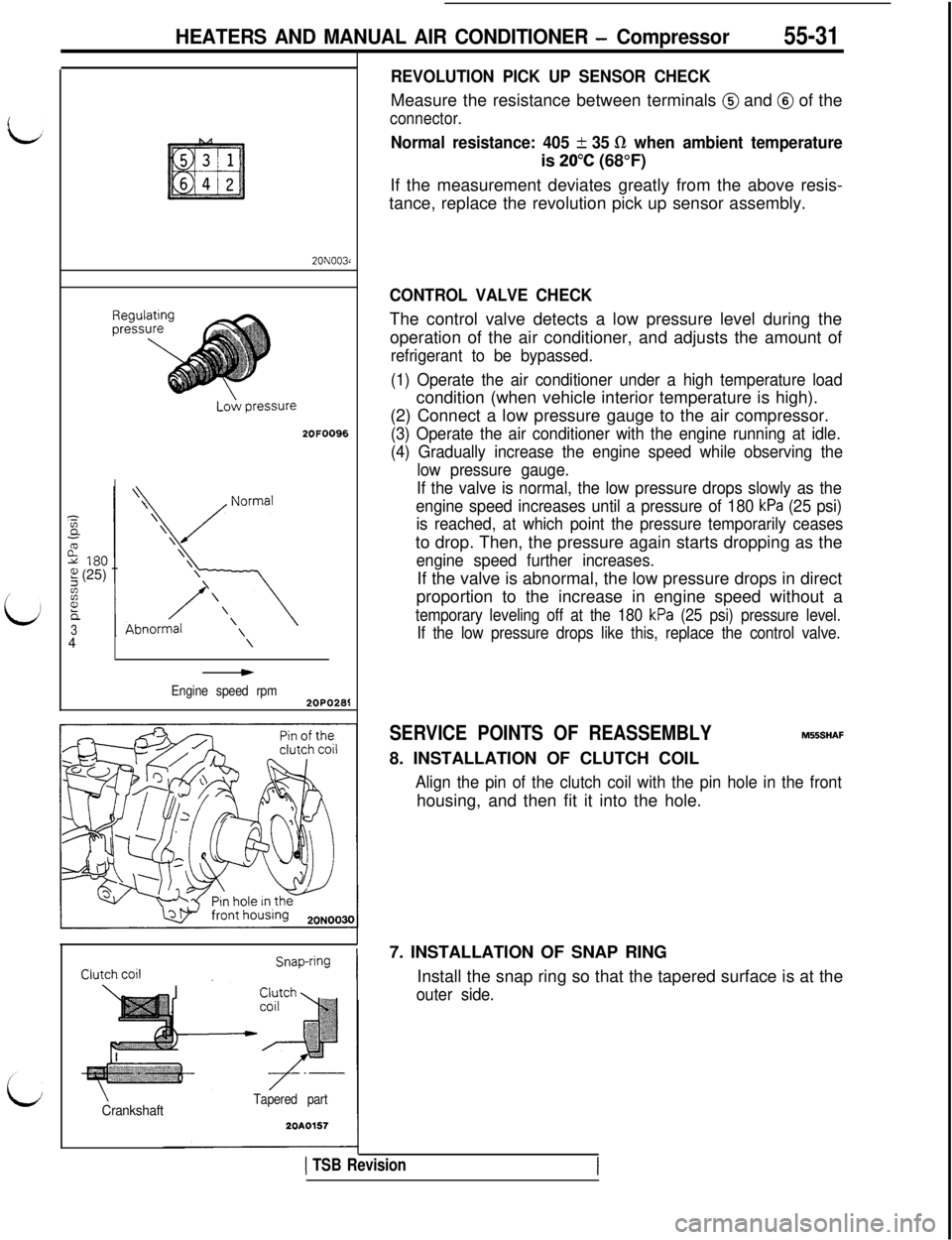
HEATERS AND MANUAL AIR CONDITIONER - Compressor55-3120N003d
2OFOO96
I
Ec-3
3180?+I! (25)zz
h34\
*
Engine speed rpm2OPO2S
\CrankshaftTapered part
20A0157
REVOLUTION PICK UP SENSOR CHECKMeasure the resistance between terminals
@ and @ of the
connector.
Normal resistance: 405 + 35 R when ambient temperatureis
20°C (68°F)
If the measurement deviates greatly from the above resis-
tance, replace the revolution pick up sensor assembly.
CONTROL VALVE CHECKThe control valve detects a low pressure level during the
operation of the air conditioner, and adjusts the amount of
refrigerant to be bypassed.
(1) Operate the air conditioner under a high temperature loadcondition (when vehicle interior temperature is high).
(2) Connect a low pressure gauge to the air compressor.
(3) Operate the air conditioner with the engine running at idle.
(4) Gradually increase the engine speed while observing the
low pressure gauge.
If the valve is normal, the low pressure drops slowly as the
engine speed increases until a pressure of 180
kPa (25 psi)
is reached, at which point the pressure temporarily ceasesto drop. Then, the pressure again starts dropping as the
engine speed further increases.If the valve is abnormal, the low pressure drops in direct
proportion to the increase in engine speed without a
temporary leveling off at the 180 kPa (25 psi) pressure level.
If the low pressure drops like this, replace the control valve.
SERVICE POINTS OF REASSEMBLYM556HAF
8. INSTALLATION OF CLUTCH COIL
Align the pin of the clutch coil with the pin hole in the fronthousing, and then fit it into the hole.
7. INSTALLATION OF SNAP RING
Install the snap ring so that the tapered surface is at the
outer side.
1 TSB Revision