Page 854 of 1146

37A-26
STEERING - Power Steerina Gear Box
Apply grease
Approx. 1 mm
l-(Approx. .040 in.)
Tool
13POO76
End plug
Sealant
13K130
’ IEnd plug
r=13K132
MB991 006-01
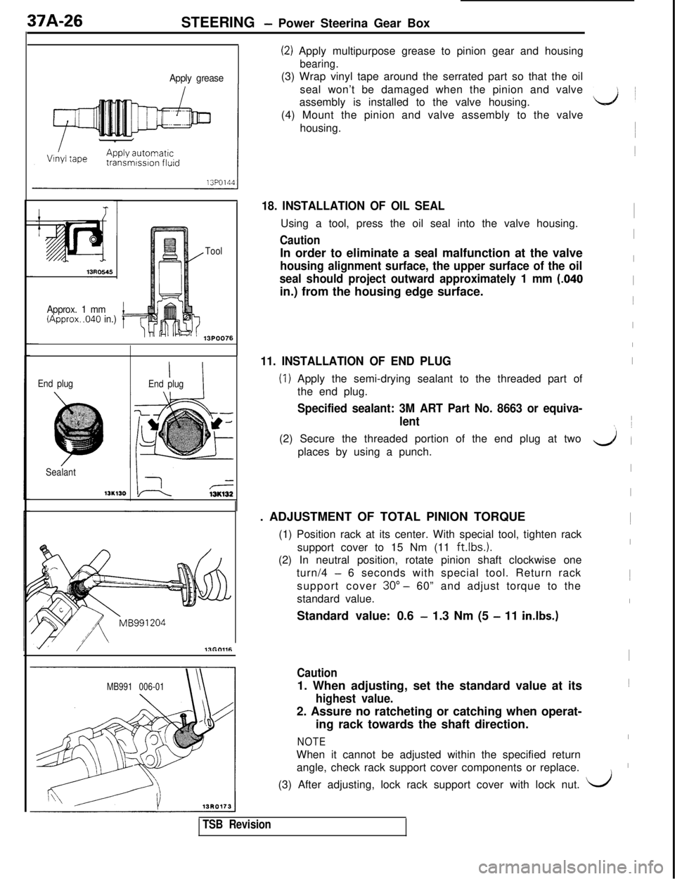
(2) Apply multipurpose grease to pinion gear and housing
bearing.(3) Wrap vinyl tape around the serrated part so that the oil
seal won’t be damaged when the pinion and valve
assembly is installed to the valve housing.
(4) Mount the pinion and valve assembly to the valve
housing.
18. INSTALLATION OF OIL SEALUsing a tool, press the oil seal into the valve housing.
CautionIn order to eliminate a seal malfunction at the valve
housing alignment surface, the upper surface of the oil
seal should project outward approximately 1 mm
(.040in.) from the housing edge surface.
11. INSTALLATION OF END PLUG
(1) Apply the semi-drying sealant to the threaded part of
the end plug.
Specified sealant: 3M ART Part No. 8663 or equiva-
lent(2) Secure the threaded portion of the end plug at two
places by using a punch.
. ADJUSTMENT OF TOTAL PINION TORQUE
(1) Position rack at its center. With special tool, tighten rack
support cover to 15 Nm (11
ft.lbs.1.(2) In neutral position, rotate pinion shaft clockwise one
turn/4
- 6 seconds with special tool. Return rack
support cover 30”
- 60” and adjust torque to the
standard value.
Standard value: 0.6
- 1.3 Nm (5 - 11 in.lbs.)
Caution1. When adjusting, set the standard value at its
highest value.2. Assure no ratcheting or catching when operat-
ing rack towards the shaft direction.
NOTEWhen it cannot be adjusted within the specified return
angle, check rack support cover components or replace.
ii1
I1
I
I
I
I1
I
I
I
I
yl (
I
I1
I1
I
I1
I
I\(3) After adjusting, lock rack support cover with lock nut.
i/
TSB Revision
Page 914 of 1146
42-42BODY -Door Trim and Waterproof Film / Door Glass and Regulator
ISERVICE POINT OF REMOVAL
1. REMOVAL OF CLIP
IUse a shop towel to remove the clip; and remove door
window regulator handle.
\L.J II
DOOR GLASS AND REGULATORREMOVAL AND INSTALLATION
~;:;zL4., 1l Door Window Glass Adjustment
18FOlQi2
Removal steps
Door trim (Refer to P.42-41
.IWaterproof film (Refer to P.42-41 .I
1. Delta cover inner
2. Delta cover outer
Door belt line outer weatherstrip
(Refer to
P.42-65.)3. up stop
4. Stabilizer inner front
5. Stabilizer inner rear
6. Delta sash
7. Door window glass
8. Door glass guide track front
9. Door window regulator assemblyIO. Door glass guide track rear
IM42MCCA
18FO200
d
I
I
I
!
(
I
L&lTSB Revision
Page 955 of 1146

EXTERIOR - Garnishes and Mouldings51-17
Protective tape/
i
I18FO181
Pressure sensitive
double-sided tape
Resin spatulaSERVICE POINT OF REMOVAL
8. REMOVAL OF SIDE GARNISH
(1) Remove the side garnish mounting nuts.
(2) Affix protective tape to the periphery of the side
garnish.
(3) Insert a fishing line
[@0.8 mm (03 in.)] between the
body and the side garnish and grip each end of the
fishing line. Cut through adhesive material by pulling
wire in a sawing motion and remove the side garnish.
(4) When the side qarnish is fastened with a clip or bolt,
pull the side garnish toward you to remove the clip or
the bolt.
Caution
1. To reuse the side garnish, remove it by pulling
the fishing line along the body so as not to
damage the edges of the side garnish.
2. If it is hard to cut through adhesive material,
heat it to approx.
40°C (104°F).-I
TSB Revision(5) Use an infrared lamp or the like to heat the pressure
sensitive double-sided tape remaining on the body to 40
to 60°C
(?04 to 140°F) for 5 to 10 minutes.
Caution
Do not overheat the tape until its surface dries to
turn white.
(6) Use a resin spatula to scrape off the pressure sensitive
adhesive double coated tape.
Page 988 of 1146

52A-10
INTERIOR - Instrument Panel
8. REMOVAL OF CENTER AIR OUTLET ASSEMBLY
Disengaging the clips of the center air outlet assembly with
a flat tip
(-1 screwdriver, remove the center air outlet
assembly with the trim stick.
IIscrewdriver/ 2OFOO321
12. REMOVAL OF SPEEDOMETER CABLE ADAPTER
(MECHANICAL TYPE SPEEDOMETER)
(1) Disconnect the speedometer cable at the transaxle end
of the cable.
(2) Remove the adapter locks from the instrument panel.
(3) Pull the speedometer cable slightly toward the passen-
ger compartment and remove the adapter.
DISASSEMBLY AND REASSEMBLY
QGlove box disassembly steps
1. Glove box stopper
2. Cross pipe cover3. Glove box cover
- w2
4. Ratchet assembly
5. Lock cylinder assembly
6. Glove box
Instrument panel disassembly steps
7. Glove box lower frame
Side air outlet
Photo sensor
Defroster garnish
Heater ducts1(Refer to GROUP
55 -Ventilators.)
Combination gauge (Refer to GROUP 54
-
Meters and Gauges.)8. Instrument panel wiring harness
19FO132
I
I
I
I
I
I1
d’
I
I
I
L&iTSB Revision
Page 1073 of 1146

Air Bag ModuleSUPPLEMENTAL RESTRAINT SYSTEM (SRS) - and Clock Spring526-6319FOlll
3
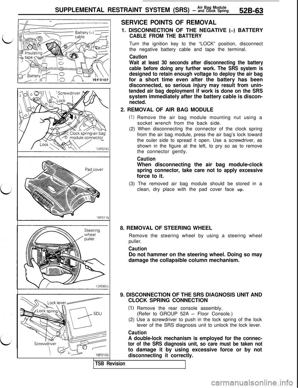
SERVICE POINTS OF REMOVAL1. DISCONNECTION OF THE NEGATIVE (-) BATTERY
CABLE FROM THE BATTERYTurn the ignition key to the “LOCK” position, disconnect
the negative battery cable and tape the terminal.
Caution
Wait at least 30 seconds after disconnecting the battery
cable before doing any further work. The SRS system is
designed to retain enough voltage to deploy the air bagfor a short time even after the battery has been
disconnected, so serious injury may result from unin-
tended air bag deployment if work is done on the SRSsystem immediately after the battery cable is discon-
nected.2. REMOVAL OF AIR BAG MODULE
(1) Remove the air bag module mounting nut using a
socket wrench from the back side.
(2) When disconnecting the connector of the clock spring
from the air bag module, press the air bag’s lock toward
the outer side to spread it open. Use a screwdriver, as
shown in the figure at the left, to pry so as to remove
the connector gently.
CautionWhen disconnecting the air bag module-clock
spring connector, take care not to apply excessiveforce to it.
(3) The removed air bag module should be stored in a
clean, dry place with the pad cover face up.
8. REMOVAL OF STEERING WHEEL
Remove the steering wheel by using a steering wheel
puller.
CautionDo not hammer on the steering wheel. Doing so may
damage the collapsible column mechanism.
9. DISCONNECTION OF THE SRS DIAGNOSIS UNIT AND
CLOCK SPRING CONNECTION
(1) Remove the rear console assembly.
(Refer to GROUP 52A
- Floor Console.)
(2) Use a screwdriver to push in the lock spring of the lock
lever of the SRS diagnosis unit to unlock the lock lever.
Caution
A double-lock mechanism is employed for the connec-
tor of the SRS diagnosis unit, so care must be taken notto damage it by using excessive force or by not
disconnecting it correctly.
TSB Revision
Page 1103 of 1146
HEATERS AND MANUAL AIR CONDITIONER - Air Condikner Switch55-21
AIR CONDITIONER SWITCH
L
REMOVAL AND INSTALLATIONRemoval steps
1. Center air outlet assembly
2. Air conditioner switch
II/J2OFOO95
M55QA- *
1
I I\L!Y,“~ s/
//
L/
l-----L-I
SERVICE POINTS OF REMOVALM55QBAH1. REMOVAL OF CENTER AIR OUTLET ASSEMBLY
Disengaging the clips (2 positions) of the center air outlet
assembly with a flat tip screwdriver, remove the center airoutlet assembly with the trim stick.
2. REMOVAL OF AIR CONDITIONER SWITCH
Remove the center air outlet assembly, and insert hand tothe back of the cluster panel assembly through the
produced opening. Push it toward you for removal.
INSPECTION
AIR CONDITIONER SWITCH CHECKM55QCAD
OFF.
0
light
If pressed 1 step (ECONOMY)
If pressed 2 steps(Air conditioner)
NOTE(1) The O-O symbol indicates continuity(2) *: 20A018ITSB Revision
Page 1108 of 1146
55-26HEATERS AND MANUAL AIR CONDITIONER - Evaporator
DISASSEMBLY AND REASSEMBLYM55RE- -Compressor oil: Freol S-83 or
Suniso 5GS
Disassembly steps
4*1. Clips
2. Evaporater case (upper)3.
Fin therm0 sensor4. AirInlet sensor
4*
5. Evaporator case (lower)
6.Evaporator assembly
7.Grommet8.Insulator9.Rubber insulator10.Clip11. Expansion valve
10/
9
/2OFOO40
1TSB Revision
SERVICE POINTS OF DISASSEMBLYM55RFAJ1. REMOVAL OF CLIPS
Remove the clips with a screwdriver covered with a shoptowel to prevent damage to case surfaces.
11. REMOVAL OF EXPANSION VALVE
Loosen the flare nut by using two wrenches (for both theinlet and outlet).
Page 1110 of 1146

55-28HEATERS AND MANUAL AIR CONDITIONER - Comtxessor
20F0067
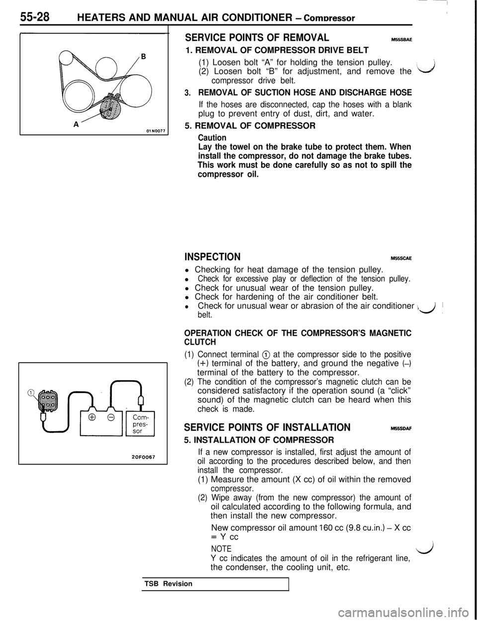
SERVICE POINTS OF REMOVALM55SBAE1. REMOVAL OF COMPRESSOR DRIVE BELT
(1) Loosen bolt “A” for holding the tension pulley.
(2) Loosen bolt “B” for adjustment, and remove the
‘J
compressor drive belt.
3.REMOVAL OF SUCTION HOSE AND DISCHARGE HOSE
If the hoses are disconnected, cap the hoses with a blankplug to prevent entry of dust, dirt, and water.
5. REMOVAL OF COMPRESSOR
Caution
Lay the towel on the brake tube to protect them. When
install the compressor, do not damage the brake tubes.
This work must be done carefully so as not to spill the
compressor oil.
INSPECTIONM55SCAEl Checking for heat damage of the tension pulley.
l
Check for excessive play or deflection of the tension pulley.l Check for unusual wear of the tension pulley.
l Check for hardening of the air conditioner belt.
lCheck for unusual wear or abrasion of the air conditioner ,
belt.
\d’
OPERATION CHECK OF THE COMPRESSOR’S MAGNETIC
CLUTCH
(1) Connect terminal @ at the compressor side to the positive
(+) terminal of the battery, and ground the negative (-)terminal of the battery to the compressor.
(2) The condition of the compressor’s magnetic clutch can beconsidered satisfactory if the operation sound (a “click”
sound) of the magnetic clutch can be heard when this
check is made.
SERVICE POINTS OF INSTALLATIONM55SDAF5. INSTALLATION OF COMPRESSOR
If a new compressor is installed, first adjust the amount of
oil according to the procedures described below, and then
install the compressor.(1) Measure the amount (X cc) of oil within the removed
compressor.
(2) Wipe away (from the new compressor) the amount ofoil calculated according to the following formula, and
then install the new compressor.
New compressor oil amount
160 cc (9.8 cu.in.) - X cc= Y cc
NOTE
Y cc indicates the amount of oil in the refrigerant line,l/jthe condenser, the cooling unit, etc.
TSB Revision