Page 1083 of 1146

55-1
HEATER, AIR
CONDITIONER
AND VENTILATION
CONTENTSM55AA- -
HEATERS AND AIR CONDITIONING................3HEATER UNIT*........................................................................22
SPECIFICATIONS
....................................................................3REFRIGERANT LINE................................................................35General Specifications
........................................................3RESISTOR................................................................................20Lubricants
............................................................................4SAFETY PRECAUTIONS........................................................9Sealant and Adhesive............................................................4
Service Specifications3SERVICE ADJUSTMENT PROCEDURES............................10........................................................
SPECIAL TOOLS4Charging Procedures............................................................11
i
........................................................................Charging the Refrigerant....................................................12Compressor Drive Belt Adjustment....................................11
HEATERS AND MANUAL AIR CONDITIONER5Compressor Noise................................................................16
................................................16
AIR CONDITIONER SWITCH................................................21Handling Tubing andFittings
Idle-up Operation Check....................................................17
BELT LOCK CONTROLLER20Performance Test................................................................15....................................................
BLOWER ASSEMBLYPower Relay Check............................................................17............................................................23Refrigerant Leak Repair Procedure....................................15COMPRESSOR........................................................................
27TestProcedures....................................................................10
CONDENSER AND CONDENSER FAN MOTOR................33TROUBLESHOOTING............................................................5
ENGINE COOLANT TEMPERATURE SWITCH....................
39VENTILATORS (AIR INLET AND AIR OUTLET)................38
EVAPORATOR
........................................................................
25VENTILATORS (INSTRUMENT PANEL)*............................36
HEATER CONTROL ASSEMBLY*
........................................18CONTINUED ON NEXT PAGE
SUPPLEMENTAL RESTRAINT SYSTEM (SRS)
(1)A Supplemental Restraint System (SRS), which uses a driver-side air bag, has been installed in the 3000GT.(2)The SRS includes the following components: impact sensors, SRS diagnosis unit: SRS warning light, air bagmodule, clock spring, interconnecting wiring. Other SRS-related components (that may have to be
removed/installed in connection with SRS service or maintenance) are indicated in the table of contents byan asterisk (*).
WARNING!(1)Improper service or maintenance of any component of the SRS, or any SRS-related component, can lead to
personal injury or death to service personnel (from inadvertent firing of the air bag) or to the driver (fromrendering the
SRS inoperative).(2) Service or maintenance of any SRS component or SRS-related component must be performed only at anauthorized MITSUBISHI dealer.
(3) MITSUBISHI dealer personnel must thoroughly review this manual, and especially its GROUP 52B
-Supplemental Restraint System (SRS), before beginning any service or maintenance of any component of theSRS or any SRS-related component.
Page 1104 of 1146

55-22HEATERS AND MANUAL AIR CONDITIONER - Heater Unit
HEATER UNIT
REMOVAL AND INSTALLATION
M551A-
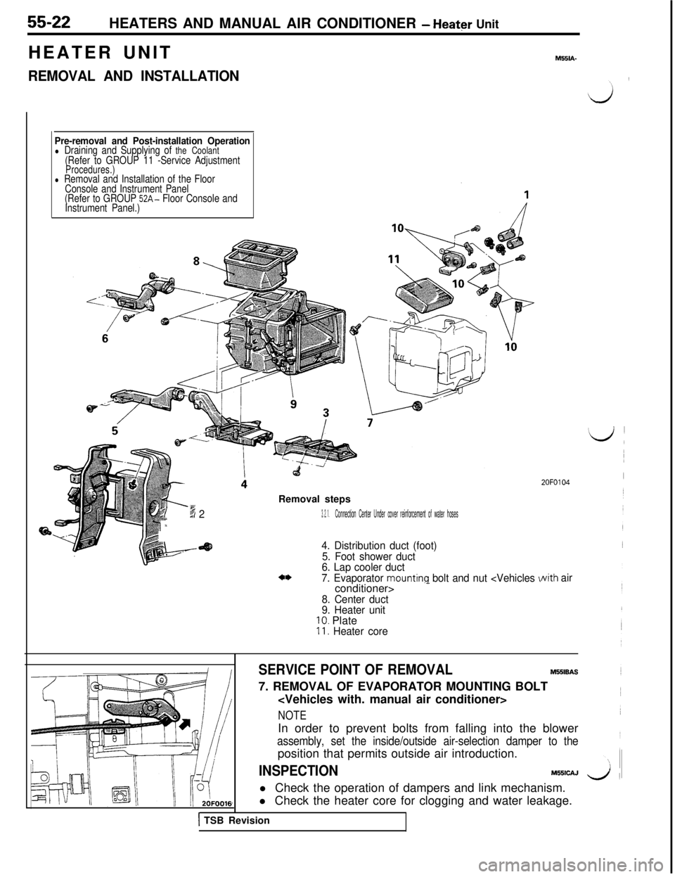
Pre-removal and Post-installation Operationl Draining and Supplying of the Coolant(Refer to GROUP 11 -Service AdjustmentProcedures.)l Removal and Installation of the Floor
Console and Instrument Panel
(Refer to GROUP
52A- Floor Console and
Instrument Panel.)Removal steps
-6 dx23. 2. 1.Connection Center Under cover reinforcement of water hoses
4. Distribution duct (foot)
5. Foot shower duct
6. Lap cooler duct
7. Evaporator
mounting bolt and nut -
8. Center duct
9. Heater unit
10. Plate11. Heater core
2OFO104
Nith air
SERVICE POINT OF REMOVALM551BAS7. REMOVAL OF EVAPORATOR MOUNTING BOLT
NOTEIn order to prevent bolts from falling into the blower
assembly, set the inside/outside air-selection damper to theposition that permits outside air introduction.
INSPECTIONM55lCAJ
l Check the operation of dampers and link mechanism.
l Check the heater core for clogging and water leakage.
1 TSB Revision
Page 1118 of 1146
55-36 HEATERS AND MANUAL AIR CONDITIONER -Ventilators (Instrument Panel)
VENTILATORS (INSTRUMENT PANEL)M55YA- -
REMOVAL AND INSTALLATION
-16
/‘4
Removal steps
l * +a1. Knee protector
(Refer to GROUP 52A-Instrument Panel.)
2. Foot shower duct
3. Lap cooler duct
4. Under cover
5. Belt lock controller
6. Side defroster hoses A
7. Duct (Vehicles without air conditioner)
** l +8. instrument panel (Refer to GROUP 52A-instrument Panel.)
9. Center duct
10. Air duct (right side)
11. Air duct (left side)12. Distribution duct (center)
13.Defroster duct14. Side defroster hoses B
15. Defroster garnishes
16.Photo sensor17. Center air outlet assembly
18. Side air outlet assembly
19. Distribution duct (foot)2OFOO55
Ij
I
I
I
.I
I
I
!
I
‘d
TSB RevisionI
Page 1119 of 1146
HEATERS AND MANUAL AIR CONDITIONER -Ventilators (Instrument Panel) 55-37
/ 2OFOO321
SERVICE POINTS OF REMOVALM55YBAH
15. REMOVAL OF DEFROSTER GARNISHES
Using the trim stick, remove the defroster garnishes fromthe instrument panel.
16. REMOVAL OF PHOTO SENSORUsing the trim stick, remove the photo sensor from the
defroster garnish.
17. REMOVAL OF CENTER AIR OUTLET ASSEMBLY
Disengaging the clips (2 positions) of the center air-outlet
assembly with a flat tip screwdriver, remove the center airoutlet assembly with the trim stick.
1 TSB Revision
Page 1135 of 1146

FULL AUTO AIR CONDITIONER - Troubleshootina55-53r
---.__------
2OFOO8:
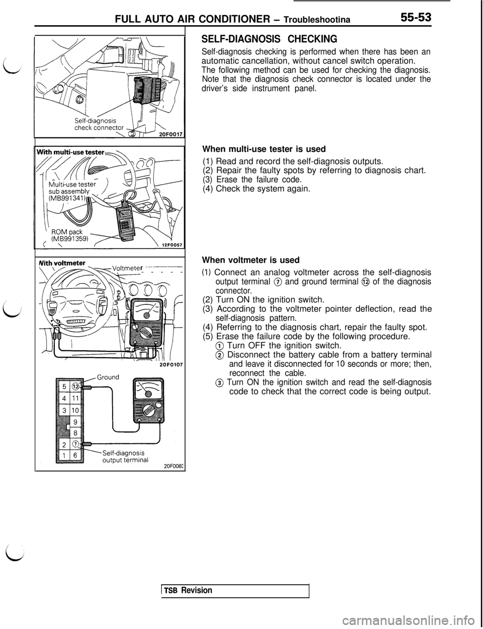
SELF-DIAGNOSIS CHECKING
Self-diagnosis checking is performed when there has been anautomatic cancellation, without cancel switch operation.
The following method can be used for checking the diagnosis.
Note that the diagnosis check connector is located under the
driver’s side instrument panel.When multi-use tester is used
(1) Read and record the self-diagnosis outputs.
(2) Repair the faulty spots by referring to diagnosis chart.
(3) Erase the failure code.(4) Check the system again.
When voltmeter is used
(1) Connect an analog voltmeter across the self-diagnosis
output terminal @ and ground terminal @ of the diagnosis
connector.(2) Turn ON the ignition switch.
(3) According to the voltmeter pointer deflection, read the
self-diagnosis pattern.(4) Referring to the diagnosis chart, repair the faulty spot.
(5) Erase the failure code by the following procedure.
@ Turn OFF the ignition switch.
@ Disconnect the battery cable from a battery terminal
and leave it disconnected for 10 seconds or more; then,
reconnect the cable.
@ Turn ON the ignition switch and read the self-diagnosiscode to check that the correct code is being output.
1 TSB Revision