Page 987 of 1146
INTERIOR - Instrument Panel52A-9
REMOVAL AND INSTALLATION
Pre-removal and Post-installation Operationl Removal and Installation of Floor Console
(Refer to P.52A-11.)
19FO131Removal steps
1. Hood lock release handle
2. Rheostat
3. Switch garnish B
4. Knee protector assembly
5. Column cover
6. Glove box striker
7. Glove box and cross pipe cover
8. Center air outlet assembly
9. Heater control assembly installation screws
10. Meter bezel
i*11. Combination meter
12. Speedometer cable adapter (Mechanical
type speedometer)
13. Speaker or plug
14. Harness connector
15. Steering shaft mounting bolts
16. Instrument panel assembly
Front ofSERVICE POINTS OF REMOVAL
5. REMOVAL OF COLUMN COVER
Remove the screws and remove the column cover while
using care not to break the claws.TSB Revision
Page 988 of 1146

52A-10
INTERIOR - Instrument Panel
8. REMOVAL OF CENTER AIR OUTLET ASSEMBLY
Disengaging the clips of the center air outlet assembly with
a flat tip
(-1 screwdriver, remove the center air outlet
assembly with the trim stick.
IIscrewdriver/ 2OFOO321
12. REMOVAL OF SPEEDOMETER CABLE ADAPTER
(MECHANICAL TYPE SPEEDOMETER)
(1) Disconnect the speedometer cable at the transaxle end
of the cable.
(2) Remove the adapter locks from the instrument panel.
(3) Pull the speedometer cable slightly toward the passen-
ger compartment and remove the adapter.
DISASSEMBLY AND REASSEMBLY
QGlove box disassembly steps
1. Glove box stopper
2. Cross pipe cover3. Glove box cover
- w2
4. Ratchet assembly
5. Lock cylinder assembly
6. Glove box
Instrument panel disassembly steps
7. Glove box lower frame
Side air outlet
Photo sensor
Defroster garnish
Heater ducts1(Refer to GROUP
55 -Ventilators.)
Combination gauge (Refer to GROUP 54
-
Meters and Gauges.)8. Instrument panel wiring harness
19FO132
I
I
I
I
I
I1
d’
I
I
I
L&iTSB Revision
Page 990 of 1146
52A-12INTERIOR - Trims
19POO70
4Trim
19POO80
hornm
in.)
19POO8,
Pin
Trim
19POO8219POO80TRIMS
IM52UCW
TRIM CLIP REMOVAL/INSTALLATION
PROCE-DURES
The type of clip shown in the illustration, which is used for the
Eli ~
installation of instrument panel, should be removed and
installed by the following procedures described below.
REMOVAL
(1) Use a cross-tip (+) screwdriver to push inward the pin (at
the center of the trim clip) to a depth of about 2 mm
(.08
in.).(2) Pull the trim clip outward to remove it.
Caution
Do not push the pin inward more than necessary
because it may damage the grommet, or the pin may
fall in, if pushed too far.
INSTALLATION
(1) With the pin pulled out, insert the trim clip into the hole in
the trim.
(2) Push the pin inward until the pin’s head is flush with the
grommet.
(3) Check whether the trim is secure.
TSB Revision
Page 1012 of 1146

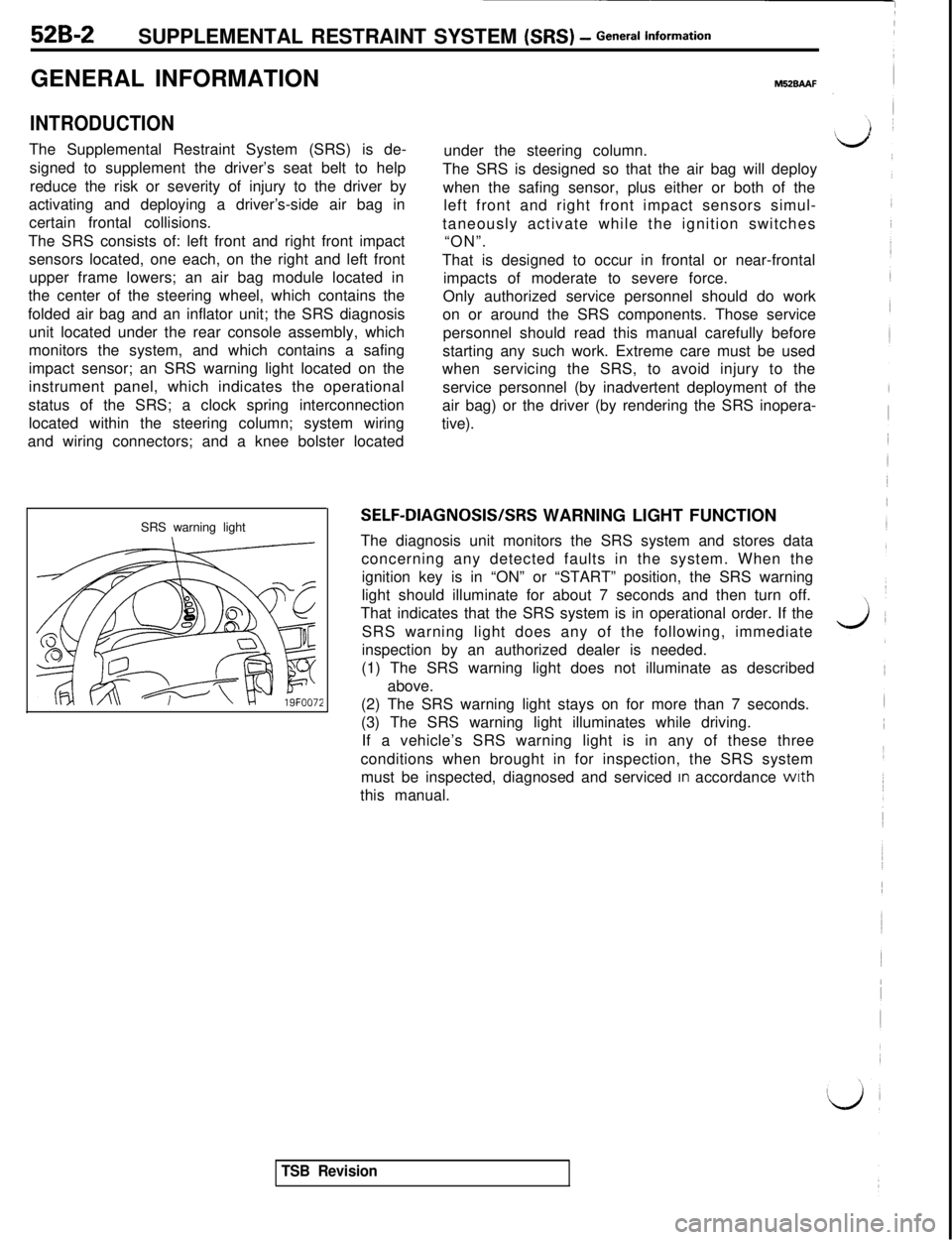
52B-2SUPPLEMENTAL RESTRAINT SYSTEM (SRS) - General informationGENERAL INFORMATION
INTRODUCTIONThe Supplemental Restraint System (SRS) is de-
signed to supplement the driver’s seat belt to help
reduce the risk or severity of injury to the driver by
activating and deploying a driver’s-side air bag in
certain frontal collisions.
The SRS consists of: left front and right front impact
sensors located, one each, on the right and left front
upper frame lowers; an air bag module located in
the center of the steering wheel, which contains the
folded air bag and an inflator unit; the SRS diagnosis
unit located under the rear console assembly, which
monitors the system, and which contains a safing
impact sensor; an SRS warning light located on the
instrument panel, which indicates the operational
status of the SRS; a clock spring interconnection
located within the steering column; system wiring
and wiring connectors; and a knee bolster located
SRS warning light
M52BAAFunder the steering column.
The SRS is designed so that the air bag will deploy
when the safing sensor, plus either or both of the
left front and right front impact sensors simul-
taneously activate while the ignition switches
“ON”.
That is designed to occur in frontal or near-frontal
impacts of moderate to severe force.
Only authorized service personnel should do work
on or around the SRS components. Those service
personnel should read this manual carefully before
starting any such work. Extreme care must be used
whenservicing the SRS, to avoid injury to the
service personnel (by inadvertent deployment of the
air bag) or the driver (by rendering the SRS inopera-
tive).
SELF-DIAGNOSIS/SRS WARNING LIGHT FUNCTION
The diagnosis unit monitors the SRS system and stores data
concerning any detected faults in the system. When the
ignition key is in “ON” or “START” position, the SRS warning
light should illuminate for about 7 seconds and then turn off.
That indicates that the SRS system is in operational order. If the
SRS warning light does any of the following, immediate
inspection by an authorized dealer is needed.
(1) The SRS warning light does not illuminate as described
above.
(2) The SRS warning light stays on for more than 7 seconds.
(3) The SRS warning light illuminates while driving.
If a vehicle’s SRS warning light is in any of these three
conditions when brought in for inspection, the SRS system
must be inspected, diagnosed and serviced
In accordance wrth
this manual.
TSB Revision
Page 1018 of 1146
52B-8SUPPLEMENTAL RESTRAINT SYSTEM (SRS) - General Information
36FOOOlJ/C-57 Clock spring
C-59 Ignition switch
C-79 Self-diagnosis check
connector (For
Multi-use Tester)
IbJInstrument panel and floor console
D-
D-03
D-04Combination meter
D-05
D-2314-pin red connector
to body wiring harness
D-24Z-pin blue connector to
right front impact sensor
D-252-pin yellow connector to
left front impact sensor
D-262-pin red connector to
clock springConnector to
SRS Diagnosis
UnitD-26225
TSB Revision,1
Page 1024 of 1146

.52B-14 SUPPLEMENTAL RESTRAINT SYSTEM (SRS) - SRS Service Precautions
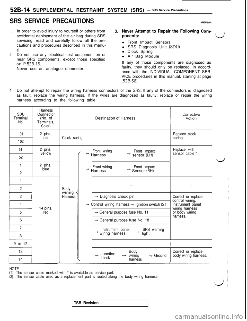
SRS SERVICE PRECAUTIONSMBZPBAA
1.In order to avoid injury to yourself or others from3.accidental deployment of the air bag during SRSNever Attempt to Repair the Following Com-servicing, read and carefully follow all the
pre-
ponents:dcautions and procedures described in this
manu-l Front Impact Sensors
al.l SRS Diagnosis Unit (SDU)
2.Do not use any electrical test equipment on orl Clock Spring
near SRS components, except those specifiedl Air Bag Module
on
P.52B-16.If any of those components are diagnosed as
Never use an analogue ohmmeter.faulty, they should only be replaced, in accord-
ance with the INDIVIDUAL COMPONENT SER-
VICE procedures in this manual, starting at page
[52B-561.
4.Do not attempt to repair the wiring harness connectors of the
SRS. If any of the connectors is diagnosed
as fault, replace the wiring harness. If the wires are diagnosed as faulty, replace or repair the wiring
harness according to the following table.
SDUTerminalNo.
Harness
Connector
(No. ofTerminals,Color)
101
102
2pins,red
51
52
2pins,yellow
12pins,
blue
2
II
II
I2 IIi
I3 I
4
t---i
14 pins,
5red
16 t
LDestination of Harness
Clock springReplace clock
spring.
Bodywiring
*
HarnessFront wiring
* HarnessFront impact+ sensor (LH)
Replace withsensor cable.*
Front wiring
--) HarnessFront impact* Sensor (RH)
--
-+ Diagnosis check pinCorrect or replace
-+ Control wiring harness+ Ignition switch (ST). control wiring,
instrument panel
-+ General purpose fuse No. 11wiring harness
or body wiringharness.+ General purpose fuse No. 18
Instrument panel+ wiring harnessSRS warning* light
-I-
~ JunctionBpdYCorrect or replace
block-+ wrnng-+ Groundharnessbody wiring harness.
NOTE(I)
(2)The sensor cable marked with * is available as service part.
The sensor cable used as a replacement part is routed along the body wiring harness.
TSB Revision
Page 1062 of 1146

52B-52 SUPPLEMENTAL RESTRAINT SYSTEM fSRSI - ~Z-%~~~~aK&%kTo air bagmodule
To SRS dragnosls unit
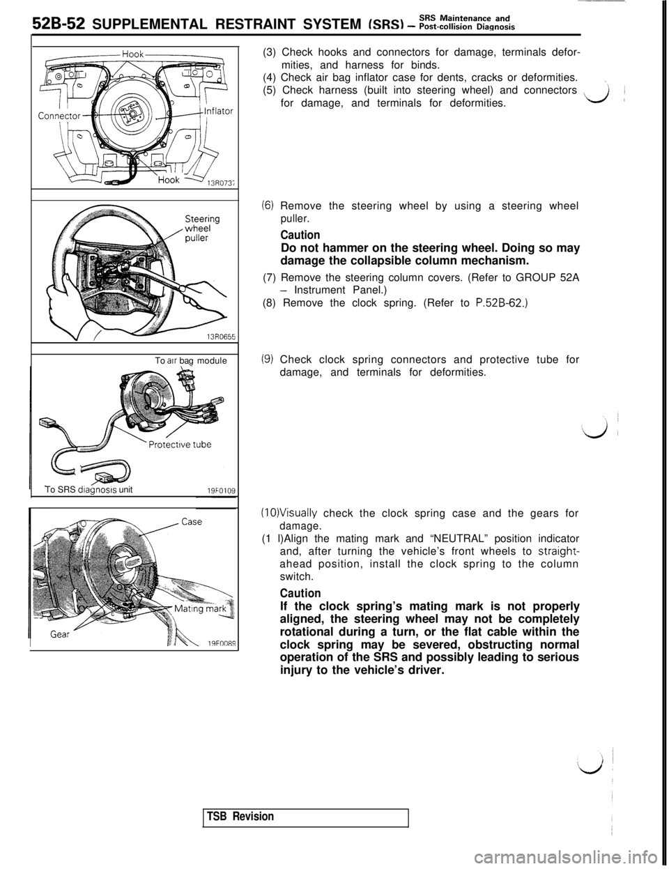
I19FOO89(3) Check hooks and connectors for damage, terminals defor-
mities, and harness for binds.
(4) Check air bag inflator case for dents, cracks or deformities.
\(5) Check harness (built into steering wheel) and connectors
~for damage, and terminals for deformities.LA
(6) Remove the steering wheel by using a steering wheel
puller.
CautionDo not hammer on the steering wheel. Doing so may
damage the collapsible column mechanism.
(7) Remove the steering column covers. (Refer to GROUP 52A
- Instrument Panel.)
(8) Remove the clock spring. (Refer to
P.52B-62.)
(9) Check clock spring connectors and protective tube for
damage, and terminals for deformities.
(10)Visually check the clock spring case and the gears for
damage.(1 l)Align the mating mark and “NEUTRAL” position indicator
and, after turning the vehicle’s front wheels to straight-
ahead position, install the clock spring to the column
switch.
CautionIf the clock spring’s mating mark is not properly
aligned, the steering wheel may not be completely
rotational during a turn, or the flat cable within the
clock spring may be severed, obstructing normal
operation of the SRS and possibly leading to serious
injury to the vehicle’s driver.
TSB Revision
Page 1072 of 1146

52B-62Air Bag ModuleSUPPLEMENTAL RESTRAINT SYSTEM (SRS) - and Clock Spring
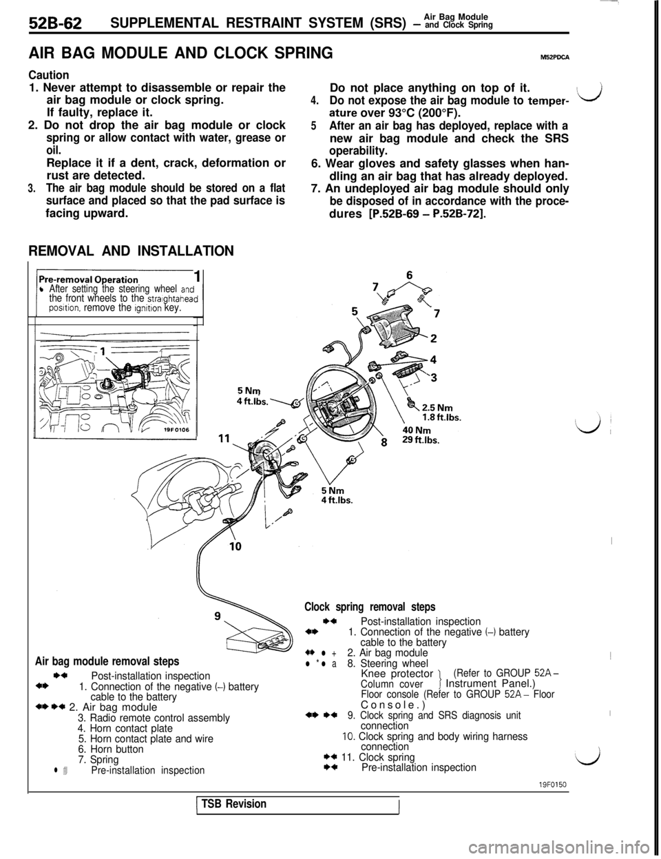
AIR BAG MODULE AND CLOCK SPRINGM52PDCA
Caution1. Never attempt to disassemble or repair the
air bag module or clock spring.
If faulty, replace it.
2. Do not drop the air bag module or clock
spring or allow contact with water, grease or
oil.Replace it if a dent, crack, deformation or
rust are detected.
3.The air bag module should be stored on a flat
surface and placed so that the pad surface isfacing upward.
REMOVAL AND INSTALLATION1
l After setting the steering wheel antthe front wheels to the stralghtaheaposltion. remove the ignition key.5NmDo not place anything on top of it.
4.Do not expose the air bag module to temper-ILJ
ature over 93°C (200°F).
5After an air bag has deployed, replace with anew air bag module and check the SRS
operability.6. Wear gloves and safety glasses when han-
dling an air bag that has already deployed.
7. An undeployed air bag module should only
be disposed of in accordance with the proce-dures
[P.52B-69 - P.52B-721.
Air bag module removal stepsI)4
Post-installation inspection4*1. Connection of the negative (-1 battery
cable to the battery
*I) I)* 2. Air bag module3. Radio remote control assembly
4. Horn contact plate
5. Horn contact plate and wire
6. Horn button
7. Spring
l 4Pre-installation inspection
Clock spring removal steps
I)4Post-installation inspection4*1. Connection of the negative (-1 battery
cable to the battery
+* l +2. Air bag modulel * l a8. Steering wheelKnee protector 1(Refer to GROUP 52A-
Column coverJ Instrument Panel.)Floor console (Refer to GROUP 52A- FloorConsole.)
*I) *+9. Clock spring and SRS diagnosis unitconnection10. Clock spring and body wiring harness
connection
I)* 11. Clock springI)4Pre-installation inspection
I1
I
‘d
1 TSB Revision
19FO150
III