1991 MITSUBISHI 3000GT clutch
[x] Cancel search: clutchPage 786 of 1146

35-64SERVICE BRAKES - Brake Pedal
BRAKE PEDAL
REMOVAL AND INSTALLATIONM35GA-
-
Post-installation Operationl Installation of Steering Column
Assembly
(Refer to GROUP
37A-SteeringWheel and Shaft.)l Clutch Pedal Adjustment
(Refer to GROUP 21 -Clutch Pedal.)
l Brake Pedal Adjustment
(Refer to
P.3545.)
Stop light switch removal steps
I. Stop light switch connector
2. Stop light switch
Brake pedal removal steps
I)* 3. Return spring
4. Cotter pin
5. Washer
6. Clevis pin
9. Brake pedal assembly
(parts from step
10 to step 21)10. Brake pedal shaft bolt
13. Brake pedal
14. Bushing
15. Spacer
l * l * 20. Clutch pedal (Refer to Group 2
Pedal.)1 -Clutch
21. Brake pedal support member
30 Nmftlbs.
’ 12Nm9 ft.lbs.
c-iA.14
14FO10614
l?
14AO2564 5
%
,36il4”OOS,
. .
I
I~
d
I
I
I
I
I~11~
d,
TSB Revision
Page 1085 of 1146
HEATER, AIR CONDITIONER AND VENTILATION - Specifications55-3
HEATER, AIR CONDITIONER AND VENTILATION
LSPECIFICATIONSM55CA. -
/’
L;
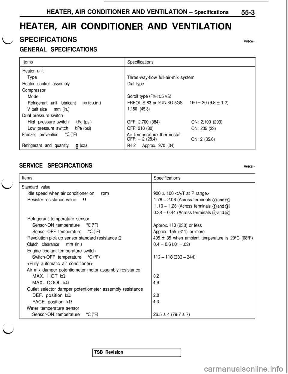
GENERAL SPECIFICATIONS
Items
Heater unit
Type
Heater control assembly
Compressor
Model
Refrigerant unit lubricant
cc (cu.in.1
V belt sizemm (in.)
Dual pressure switch
High pressure switch
kPa (psi)
Low pressure switchkPa (psi)
Freezer prevention
“C (“F)
Refrigerant and quantityg (oz.)
Specifications
Three-way-flow full-air-mix system
Dial type
Scroll type (FX-105 VS)
FREOL S-83 or SUNISO 5GS160 & 20 (9.8 + 1.2)
1,150 (45.3)
OFF: 2,700 (384)ON: 2,100 (299)
OFF: 210 (30)
ON
: 235 (33)
Air temperature thermostatOFF: - 2 (28.4)
ON: 2 (35.6)
R-l 2Approx. 970 (34)
SERVICE SPECIFICATIONSM55CB. -
Items
Standard value
Idle speed when air conditioner onrpm
Resister resistance value1R
Refrigerant temperature sensor
Sensor-ON temperature
“C (“F)
Sensor-OFF temperature“C (“F)
Revolution pick up sensor standard resistance 0
Clutch clearancemm (in.)
Engine coolant temperature switch
Switch-OFF temperature
“C (“F)
Air mix damper potentiometer motor assembly resistanceMAX. HOT
kQMAX. COOL
kS1
Outlet selector damper potentiometer assembly resistanceDEF. position
kS1FACE position
kfl
Water temperature sensor
Sensor-ON temperature
“C (“F)
Specifications
900
f 100 CA/T at P range>
1.76
- 2.06 (Across terminals @and 0)
1 .I 0 - 1.26 (Across terminals @and 0)
0.38 - 0.44 (Across terminals @and @)
Approx. 110 (230) or less
Approx. 155 (311) or more
405
f 35 when ambient temperature is 20°C (68°F)
0.4 - 0.6 (.Ol - .02)
112-118(233-244)
0.2
4.9
2.0
4.3
26.5 f 4 (79.7 + 7)
TSB Revision
Page 1090 of 1146
55-8HEATERS AND MANUAL AIR CONDITIONER - Troubleshooting
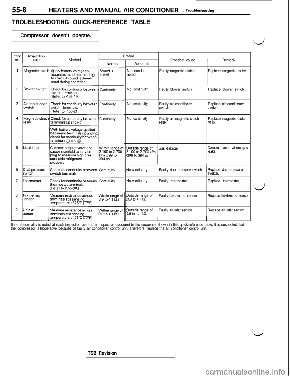
TROUBLESHOOTING QUICK-REFERENCE TABLE
Compressor doesn’t operate.
hen
no.
4
5
6
7
8
9
-
I
I
/
L
switch terminals.
Sensor
”
1
InspectronCriteriapointIMethodProbable causeIRemedy
Abnormal
No sound is
notedFaulty magnetic clutchReplace magnetic clutch.
No continuity
Faulty blower switchReplace blower switch
No continuity
Faulty air conditioner
switchReplace air conditioner
switch.
No continuity
Faulty air magnetic clutch
relayReplace magnetic clutch
relay.
pa;?’ places where gas
II
Vo continuityFaulty dual-pressure switchReplace dual-pressure
\Jo continuityIFaulty thermostatswitch.Replace thermostat.
Outside range of3.9 to 4.1 kfiFaulty fin-therm0 sensorReplace fin-therm0 sensor
3utside range ofFaulty air inlet sensor1.9tol.l kQReplace air inlet sensor.
If no abnormality
is noted at each inspection point after inspection coducted in the sequence shown in this quick-reference table, it is suspected that
the compressor IS Inoperative because of faulty air conditioner control unit. Therefore, replace the air conditioner control unit.
d
d
TSB Revision
Page 1092 of 1146
55-10 HEATERS AND MANUAL AIR CONDITIONER -Service Adjustment Procedures
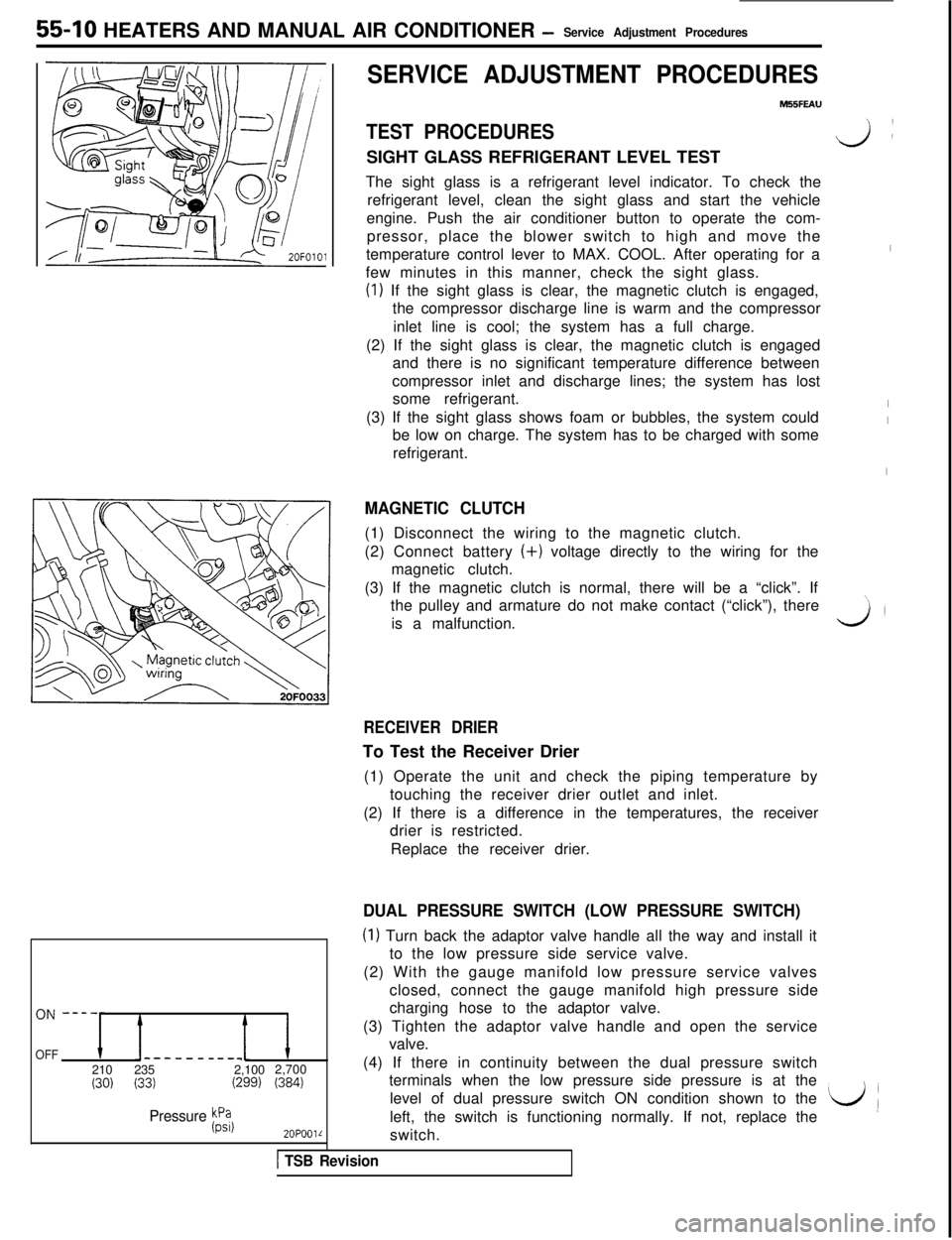
OFF-----__-__1210235 2,1002,700
(30) (33)(299) (384)
Pressure Fil
2OPOOlL
SERVICE ADJUSTMENT PROCEDURES
M55FEAU
TEST PROCEDURESSIGHT GLASS REFRIGERANT LEVEL TEST
The sight glass is a refrigerant level indicator. To check the
refrigerant level, clean the sight glass and start the vehicle
engine. Push the air conditioner button to operate the com-
pressor, place the blower switch to high and move the
temperature control lever to MAX. COOL. After operating for a
few minutes in this manner, check the sight glass.
(I) If the sight glass is clear, the magnetic clutch is engaged,
the compressor discharge line is warm and the compressor
inlet line is cool; the system has a full charge.
(2) If the sight glass is clear, the magnetic clutch is engaged
and there is no significant temperature difference between
compressor inlet and discharge lines; the system has lost
some refrigerant.
(3) If the sight glass shows foam or bubbles, the system could
be low on charge. The system has to be charged with some
refrigerant.
MAGNETIC CLUTCH(1) Disconnect the wiring to the magnetic clutch.
(2) Connect battery (+) voltage directly to the wiring for the
magnetic clutch.
(3) If the magnetic clutch is normal, there will be a “click”. If
the pulley and armature do not make contact (“click”), there
is a malfunction.
v):
I
I
I
I
\,
3’
RECEIVER DRIERTo Test the Receiver Drier
(1) Operate the unit and check the piping temperature by
touching the receiver drier outlet and inlet.
(2) If there is a difference in the temperatures, the receiver
drier is restricted.
Replace the receiver drier.
DUAL PRESSURE SWITCH (LOW PRESSURE SWITCH)
(I) Turn back the adaptor valve handle all the way and install it
to the low pressure side service valve.
(2) With the gauge manifold low pressure service valves
closed, connect the gauge manifold high pressure side
charging hose to the adaptor valve.
(3) Tighten the adaptor valve handle and open the service
valve.
(4) If there in continuity between the dual pressure switch
terminals when the low pressure side pressure is at the
level of dual pressure switch ON condition shown to the
left, the switch is functioning normally. If not, replace the
L/(switch.
1 TSB Revision
Page 1097 of 1146
L/
i
HEATERS AND MANUAL AIR CONDITIONER -Service Adjustment Procedures 55 15
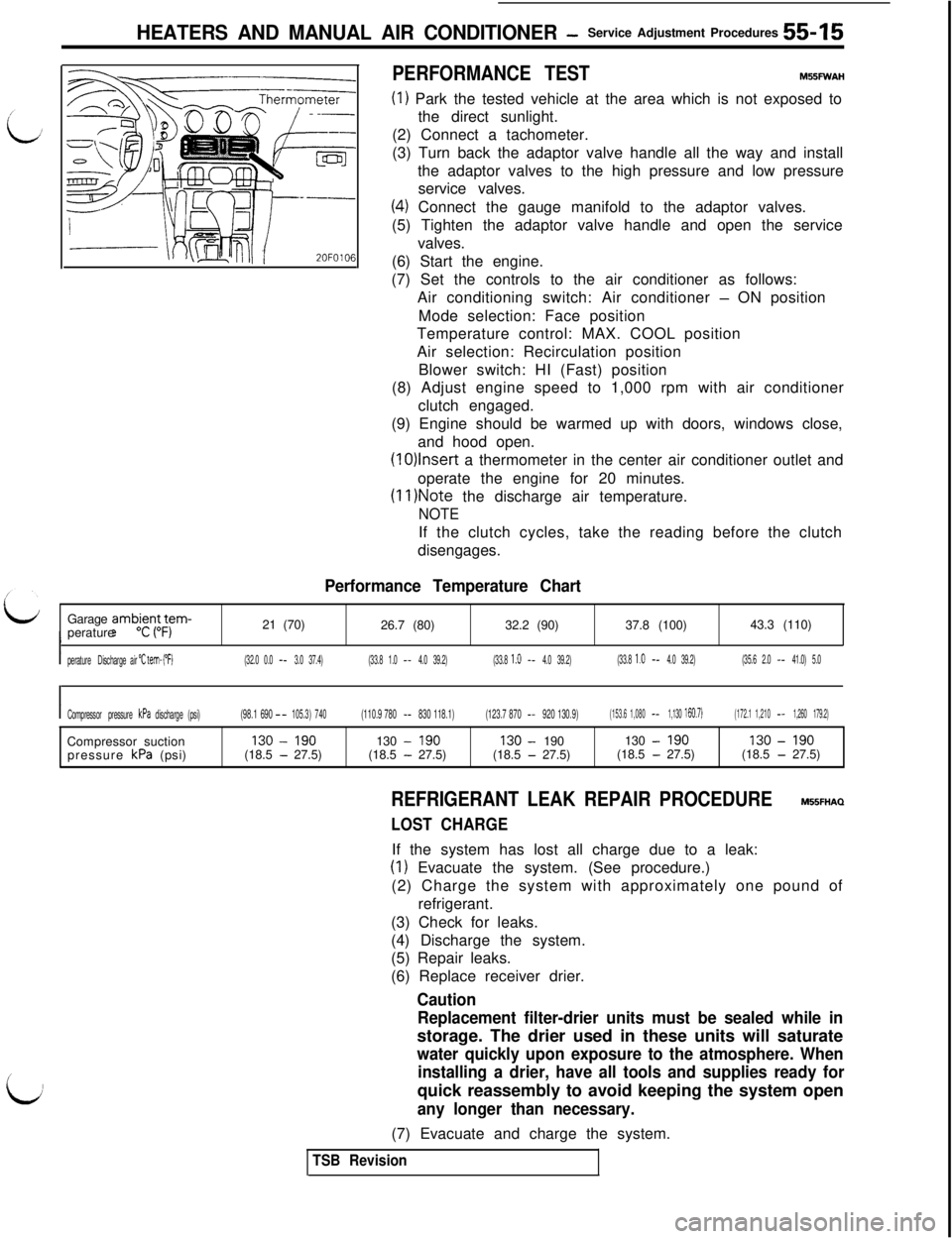
PERFORMANCE TESTM55FWAH
(I) Park the tested vehicle at the area which is not exposed to
the direct sunlight.
(2) Connect a tachometer.
(3) Turn back the adaptor valve handle all the way and install
the adaptor valves to the high pressure and low pressure
service valves.
(4) Connect the gauge manifold to the adaptor valves.
(5) Tighten the adaptor valve handle and open the service
valves.
(6) Start the engine.
(7) Set the controls to the air conditioner as follows:
Air conditioning switch: Air conditioner
- ON position
Mode selection: Face position
Temperature control: MAX. COOL position
Air selection: Recirculation position
Blower switch: HI (Fast) position
(8) Adjust engine speed to 1,000 rpm with air conditioner
clutch engaged.
(9) Engine should be warmed up with doors, windows close,
and hood open.
(1O)lnsert a thermometer in the center air conditioner outlet and
operate the engine for 20 minutes.
(II )Note the discharge air temperature.
NOTEIf the clutch cycles, take the reading before the clutch
disengages.
Performance Temperature ChartGarage
amb;in,L;am-perature21 (70)
26.7 (80)32.2 (90)37.8 (100)43.3 (110)
Iperature Dischargeair "C tem- ("F)(32.0 0.0- -3.0 37.4)(33.8 1.0- -4.0 39.2)(33.8 1.0- -4.0 39.2)(33.8 1.0- -4.0 39.2)(35.6 2.0- -41.0) 5.0
ICompressor pressure kPa discharge (psi)(98.1 690- -105.3) 740(110.9 780- -830 118.1)(123.7 870- -920 130.9)(153.6 1,080- -1,130 160.7)(172.1 1,210- -1,260 179.2)Compressor suction130
-190130-190130-190130-190130-190
pressure kPa (psi)(18.5-27.5)(18.5-27.5)(18.5-27.5)(18.5-27.5)(18.5-27.5)
REFRIGERANT LEAK REPAIR PROCEDUREM55FHAQ
LOST CHARGEIf the system has lost all charge due to a leak:
(1) Evacuate the system. (See procedure.)
(2) Charge the system with approximately one pound of
refrigerant.
(3) Check for leaks.
(4) Discharge the system.
(5) Repair leaks.
(6) Replace receiver drier.
Caution
Replacement filter-drier units must be sealed while instorage. The drier used in these units will saturate
water quickly upon exposure to the atmosphere. When
installing a drier, have all tools and supplies ready forquick reassembly to avoid keeping the system open
any longer than necessary.(7) Evacuate and charge the system.
TSB Revision
Page 1098 of 1146
55-16 HEATERS AND MANUAL AIR CONDITIONER -Service Adjustment Procedures
LOW CHARGE~
If the system has not lost all of its refrigerant charge; locate and
repair all leaks. If it is necessary to increase the system
pressure to find the leak (because of an especially low charge)
‘iaadd of refrigerant. If it is oossible to reoair the leak without
discharging-the refrigerant system, use the procedure for
correcting low refrigerant level.
HANDLING TUBING AND FITTINGSM55FlAFKinks in the refrigerant tubing or sharp bends in the refrigerant
hose lines will greatly reduce the capacity of the entire system.
High pressures are produced in the system when it is
operating. Extreme care must be exercised to make sure that
all connections are pressure tight. Dirt and moisture can enter
the system when it is opened for repair or replacement of lines
or components. The following precautions must be observed.
The system must be completely discharged before opening
any fitting of connection in the refrigeration system. Open
fittings with caution even after the system has been dis-
charged. If any pressure is noticed as a fitting is loosened, allow
trapped pressure to bleed off very slowly.
Never attempt to rebend formed lines to fit. Use the correct
line for the installation you are servicing.
A good rule for the flexible hose lines is keep the radius of all
bends at least 10 times the diameter of the hose.
Sharper bends will reduce the flow of refrigerant. The flexible
hose lines should be routed so that they are at least 80 mm (3
in.) from the exhaust manifold. It is good practice to inspect all
flexible hose lines at least once a year to make sure they are in
good condition and properly routed.
\ Aj iUnified plumbing connections with O-rings. These O-rings are
-not reusable.
I
COMPRESSOR NOISEM55FlAD
When investigating an air conditioning related noise, you must
first know the conditions when the noise occurs. These
conditions are: weather, vehicle speed, in gear on neutral,
engine temperature or any other special conditions.
Noises that develop during air conditioning operation can often
be misleading. For example: what sounds like a failed front
bearing or connecting rod. may be caused by loose bolts, nuts,
mounting brackets, or a loose clutch assembly. Verify acces-
sory drive belt tension (power steering or alternator).
Improper accessory drive belt tension can cause a misleading
noise when the compressor is engaged and little or no noise
when the compressor is disengaged.
Drive belts are speed sensitive. That is, at different engine
speeds, and depending upon belt tension, belts can develop
unusual noises that are often mistaken for mechanical prob-
lems within the compressor.
TSB Revision
Page 1099 of 1146
HEATERS AND MANUAL AIR CbNDlTlONER -Service Adjustment Procedures 55 17
ADJUSTMENT PROCEDURES(1) Select a quiet area for testing. Duplicate conditions as much
as possible. Switch compressor on and off several times to
clearly identify compressor noise.
To duplicate high ambient conditions (high head pressure),
restrict air flow through condenser. Install manifold gauge
set to make sure discharge pressure doesn’t exceed 2,070
kPa (300 psi).
(2) Tighten all compressor mounting bolts, clutch mounting
bolt, and compressor drive belt. Check to assure clutch coil
is tight (no rotation or wobble).
(3) Check refrigerant hoses for rubbing or interference that can
cause unusual noises.
(4) Check refrigerant charge. (See “Charging System”.)
(5) Recheck compressor noise as in Step 1.
(6) If noise still exists, loosen compressor mounting bolts and
retorque. Repeat Step 1.
(7) If noise continues, replace compressor and repeat Step 1.
POWER RELAY CHECKMBBFNAK(1) Remove the radiator fan motor relays (HI) and (LO) from the
relay box on the right of the engine compartment.
(2) Remove the radiator fan motor relay (air conditioner),
condenser fan motor relays (HI) and (LO), and
air-conditioner compressor relay from the relay box on the left
of the engine compartment.
(3) Remove the blower motor relay from the junction box.
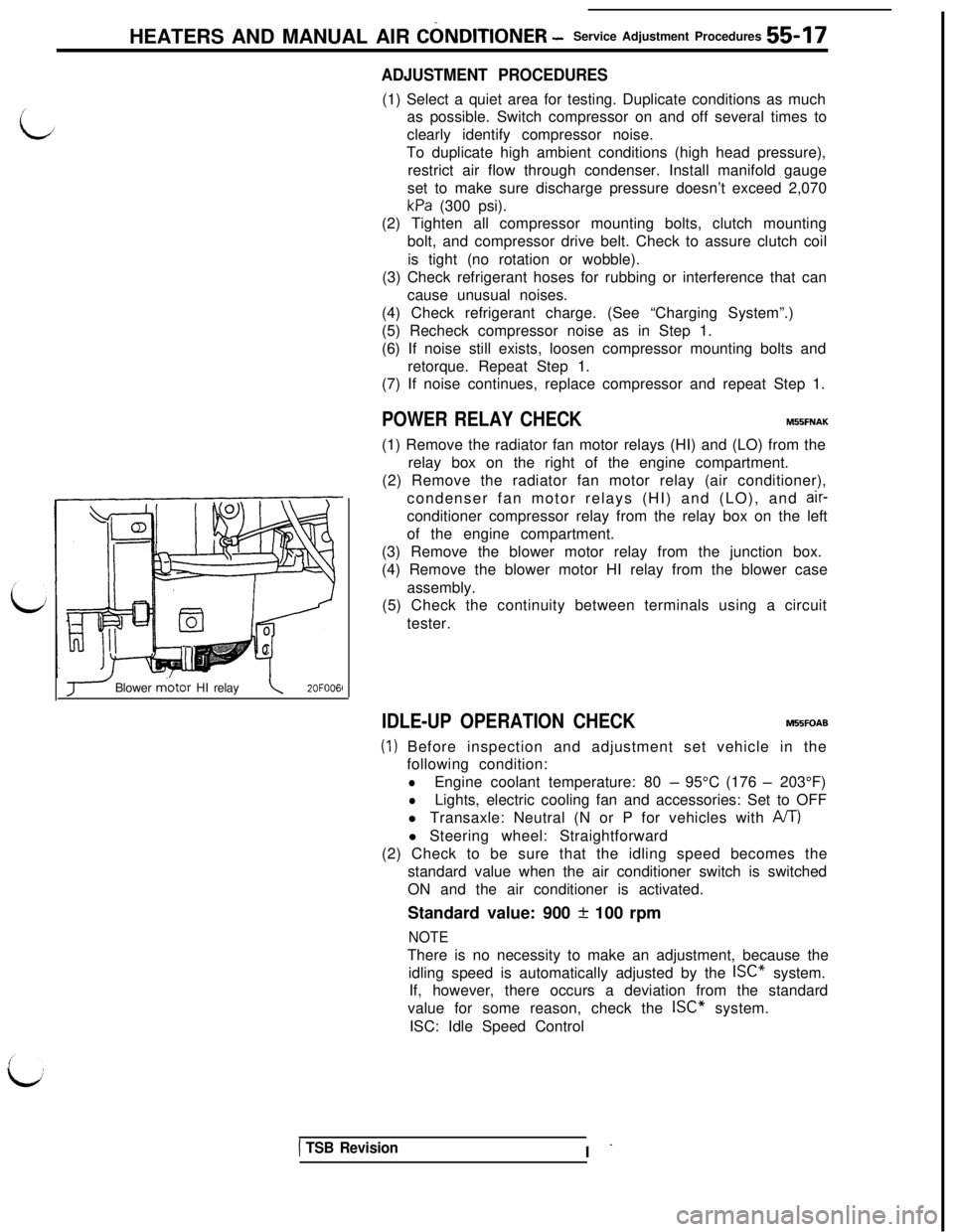
(4) Remove the blower motor HI relay from the blower case
assembly.
(5) Check the continuity between terminals using a circuit
tester.
J Blower m.otor HI relay\2OFOO6l
IDLE-UP OPERATION CHECKM55FOAB
(1) Before inspection and adjustment set vehicle in the
following condition:
lEngine coolant temperature: 80 - 95°C (176 - 203°F)
lLights, electric cooling fan and accessories: Set to OFF
l Transaxle: Neutral (N or P for vehicles with
A/T)l Steering wheel: Straightforward
(2) Check to be sure that the idling speed becomes the
standard value when the air conditioner switch is switched
ON and the air conditioner is activated.
Standard value: 900
+ 100 rpm
NOTEThere is no necessity to make an adjustment, because the
idling speed is automatically adjusted by the ISC” system.
If, however, there occurs a deviation from the standard
value for some reason, check the ISC” system.
ISC: Idle Speed Control
1 TSB RevisionI -
Page 1110 of 1146
55-28HEATERS AND MANUAL AIR CONDITIONER - Comtxessor
20F0067
SERVICE POINTS OF REMOVALM55SBAE1. REMOVAL OF COMPRESSOR DRIVE BELT
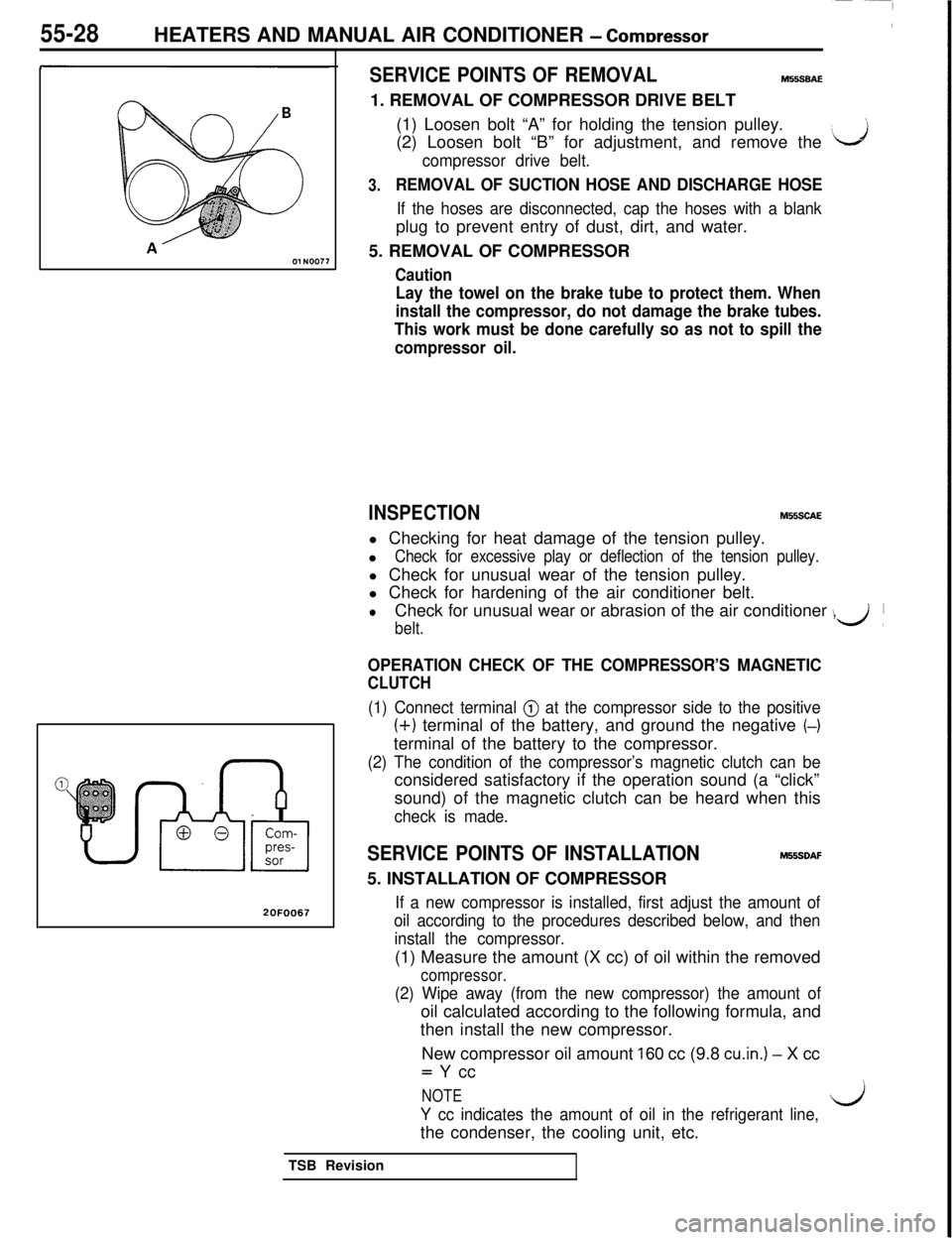
(1) Loosen bolt “A” for holding the tension pulley.
(2) Loosen bolt “B” for adjustment, and remove the
‘J
compressor drive belt.
3.REMOVAL OF SUCTION HOSE AND DISCHARGE HOSE
If the hoses are disconnected, cap the hoses with a blankplug to prevent entry of dust, dirt, and water.
5. REMOVAL OF COMPRESSOR
Caution
Lay the towel on the brake tube to protect them. When
install the compressor, do not damage the brake tubes.
This work must be done carefully so as not to spill the
compressor oil.
INSPECTIONM55SCAEl Checking for heat damage of the tension pulley.
l
Check for excessive play or deflection of the tension pulley.l Check for unusual wear of the tension pulley.
l Check for hardening of the air conditioner belt.
lCheck for unusual wear or abrasion of the air conditioner ,
belt.
\d’
OPERATION CHECK OF THE COMPRESSOR’S MAGNETIC
CLUTCH
(1) Connect terminal @ at the compressor side to the positive
(+) terminal of the battery, and ground the negative (-)terminal of the battery to the compressor.
(2) The condition of the compressor’s magnetic clutch can beconsidered satisfactory if the operation sound (a “click”
sound) of the magnetic clutch can be heard when this
check is made.
SERVICE POINTS OF INSTALLATIONM55SDAF5. INSTALLATION OF COMPRESSOR
If a new compressor is installed, first adjust the amount of
oil according to the procedures described below, and then
install the compressor.(1) Measure the amount (X cc) of oil within the removed
compressor.
(2) Wipe away (from the new compressor) the amount ofoil calculated according to the following formula, and
then install the new compressor.
New compressor oil amount
160 cc (9.8 cu.in.) - X cc= Y cc
NOTE
Y cc indicates the amount of oil in the refrigerant line,l/jthe condenser, the cooling unit, etc.
TSB Revision