Page 51 of 4087
Blower Fan Speed Control System
(When AUTO Switch is ON)
(a) The desired temperature is set using the TEMP switch.
(b) From the input signals (room temperature sensor, ambient temperature sensor and solar sensor) and thetemperature setting, the air conditioner control ECU determines the air flow volume\
and outputs signals
to the power transistor.
(c) When it receives signals from the ECU, the power transistor increases or red\
uces the blower motor speed to control the air flow volume.
(When AUTO Switch is OFF)
The ECU turns the power transistor increasing or reducing the blower mot\
or speed fixing the air flow volume
in accordance with the position of the Manual switch. AC±10
±
AIR CONDITIONING SYSTEM Description
WhereEverybodyKnowsYourName
Page 117 of 4087
������������������\
������������������\
�
������������������\
�����������������
������������������\
������������������\
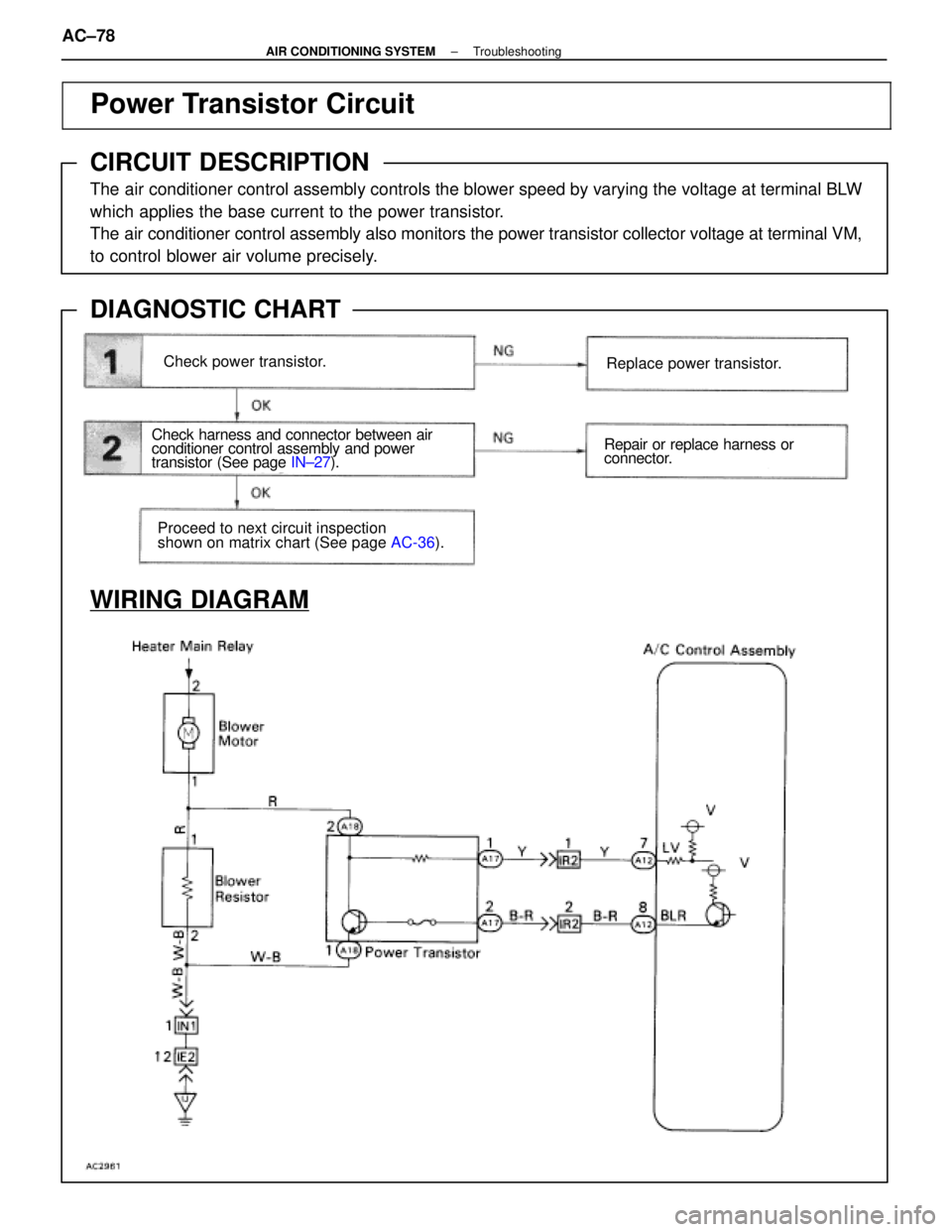
Power Transistor Circuit
CIRCUIT DESCRIPTION
The air conditioner control assembly controls the blower speed by varying the vo\
ltage at terminal BLW
which applies the base current to the power transistor.
The air conditioner control assembly also monitors the power transistor col\
lector voltage at terminal VM,
to control blower air volume precisely.
DIAGNOSTIC CHART
WIRING DIAGRAM
Check power transistor.
Check harness and connector between air
conditioner control assembly and power
transistor (See page
IN±27).
Proceed to next circuit inspection
shown on matrix chart (See page AC-36).
Replace power transistor.
Repair or replace harness or
connector.
AC±78±
AIR CONDITIONING SYSTEM Troubleshooting
WhereEverybodyKnowsYourName
Page 118 of 4087
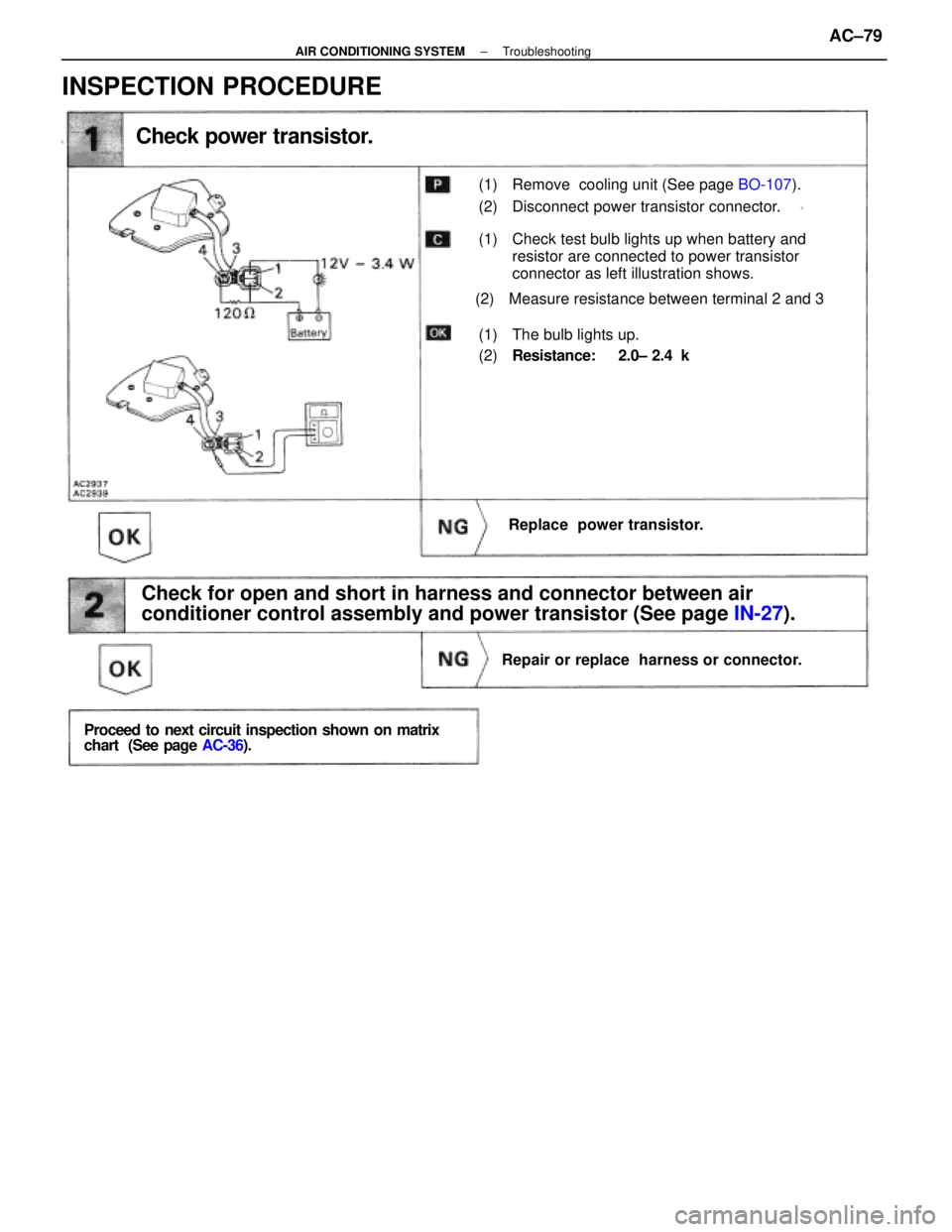
Check power transistor.
(1) Remove cooling unit (See page BO-107).
(2) Disconnect power transistor connector.
(1) Check test bulb lights up when battery and
resistor are connected to power transistor
connector as left illustration shows.
(2) Measure resistance between terminal 2 and 3
(1) The bulb lights up.
(2)Resistance: 2.0± 2.4 k �
Replace power transistor.
Check for open and short in harness and connector between air
conditioner control assembly and power transistor (See page IN-27).
Repair or replace harness or connector.
Proceed to next circuit inspection shown on matrix
chart (See page AC-36).
INSPECTION PROCEDURE
±
AIR CONDITIONING SYSTEM TroubleshootingAC±79
WhereEverybodyKnowsYourName
Page 122 of 4087
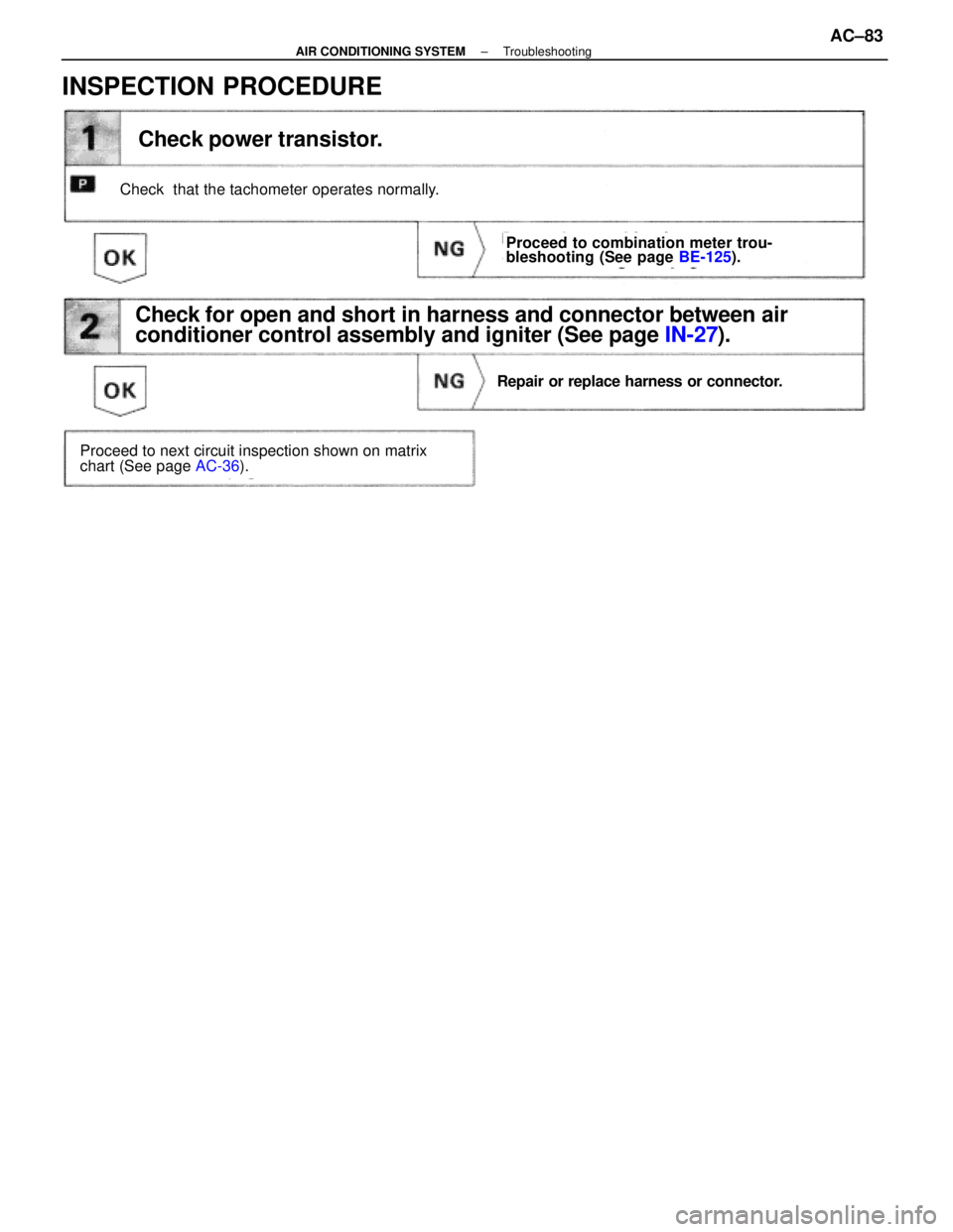
Check power transistor.
Check that the tachometer operates normally.
Proceed to combination meter trou-
bleshooting (See page BE-125).
Proceed to next circuit inspection shown on matrix
chart (See page AC-36).
Repair or replace harness or connector.
Check for open and short in harness and connector between air
conditioner control assembly and igniter (See page IN-27).
INSPECTION PROCEDURE
±
AIR CONDITIONING SYSTEM TroubleshootingAC±83
WhereEverybodyKnowsYourName
Page 174 of 4087
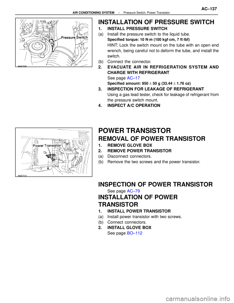
INSTALLATION OF PRESSURE SWITCH
1. INSTALL PRESSURE SWITCH
(a) Install the pressure switch to the liquid tube.
Specified torque: 10 NVm (100 kgf Vcm, 7 ft Vlbf)
HINT: Lock the switch mount on the tube with an open end
wrench, being careful not to deform the tube, and install the
switch.
(b) Connect the connector.
2. EVACUATE AIR IN REFRIGERATION SYSTEM AND CHARGE WITH REFRIGERANT
See page AC±17
Specified amount: 950 + 50 g (33.44 + 1.76 oz)
3. INSPECTION FOR LEAKAGE OF REFRIGERANT
Using a gas lead tester, check for leakage of refrigerant from
the pressure switch mount.
4. INSPECT A/C OPERATION
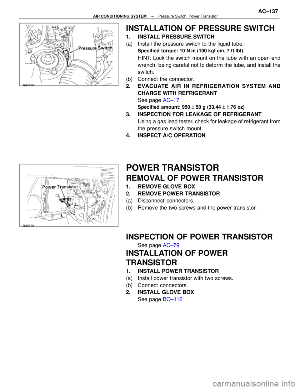
POWER TRANSISTOR
REMOVAL OF POWER TRANSISTOR
1. REMOVE GLOVE BOX
2. REMOVE POWER TRANSISTOR
(a) Disconnect connectors.
(b) Remove the two screws and the power transistor.
INSPECTION OF POWER TRANSISTOR
See page AC±79
INSTALLATION OF POWER
TRANSISTOR
1. INSTALL POWER TRANSISTOR
(a) Install power transistor with two screws.
(b) Connect connectors.
2. INSTALL GLOVE BOX
See page BO±112
±
AIR CONDITIONING SYSTEM Pressure Switch, Power TransistorAC±137
WhereEverybodyKnowsYourName
Page 175 of 4087
INSTALLATION OF PRESSURE SWITCH
1. INSTALL PRESSURE SWITCH
(a) Install the pressure switch to the liquid tube.
Specified torque: 10 NVm (100 kgf Vcm, 7 ft Vlbf)
HINT: Lock the switch mount on the tube with an open end
wrench, being careful not to deform the tube, and install the
switch.
(b) Connect the connector.
2. EVACUATE AIR IN REFRIGERATION SYSTEM AND CHARGE WITH REFRIGERANT
See page AC±17
Specified amount: 950 + 50 g (33.44 + 1.76 oz)
3. INSPECTION FOR LEAKAGE OF REFRIGERANT
Using a gas lead tester, check for leakage of refrigerant from
the pressure switch mount.
4. INSPECT A/C OPERATION
POWER TRANSISTOR
REMOVAL OF POWER TRANSISTOR
1. REMOVE GLOVE BOX
2. REMOVE POWER TRANSISTOR
(a) Disconnect connectors.
(b) Remove the two screws and the power transistor.
INSPECTION OF POWER TRANSISTOR
See page AC±79
INSTALLATION OF POWER
TRANSISTOR
1. INSTALL POWER TRANSISTOR
(a) Install power transistor with two screws.
(b) Connect connectors.
2. INSTALL GLOVE BOX
See page BO±112
±
AIR CONDITIONING SYSTEM Pressure Switch, Power TransistorAC±137
WhereEverybodyKnowsYourName
Page 1079 of 4087

DTC21, 22,23, 24ABS Actuator Solenoid Circuit
CIRCUIT DESCRIPTION
This solenoid goes on when signals are received from the ECU and controls the\
pressure acting on the wheel
cylinders, thus controlling the braking force.
DTC No.DTC Detecting ConditionTrouble Area
21
Conditions (1) through (3) continue for0.05 sec. or more:
(1) ABS solenoid relay (SR) terminalvoltage: Battery positive
voltage
(2) Voltage of ABS (& TRAC) ECU terminal AST: Battery posi-
tive voltage
(3) When power transistor of ECU is ON,voltage of terminal
SFR is 0 V or batterypositive voltage.
ABS actuator
Open or short in SFR circuit.
ECU
22
Conditions (1) through (3) continue for0.05 sec. or more:
(1) ABS solenoid relay (SR) terminalvoltage: Battery positive
voltage
(2) Voltage of ABS (& TRAC) ECU terminal AST: Battery posi-
tive voltage
(3) When power transistor of ECU is ON,voltage of terminal
SFL is 0 V or batterypositive voltage.
ABS actuator
Open or short in SFL circuit.
ECU
23
Conditions (1) through (3) continue for0.05 sec. or more:
(1) ABS solenoid relay (SR) terminalvoltage: Battery positive
voltage
(2) Voltage of ABS (& TRAC) ECU terminal AST: Battery posi-
tive voltage
(3) When power transistor of ECU is ON,voltage of terminal
SRR is 0 V or batterypositive voltage.
ABS actuator
Open or short in SRR circuit
ECU
24
(Only ve-
hicles with TRAC)
Conditions (1) through (3) continue for0.05 sec. or more:
(1) ABS solenoid relay (SR) terminalvoltage: Battery positive
voltage
(2) Voltage of ABS & TRAC ECU terminal AST: Battery posi-
tive voltage
(3) When power transistor of ECU is ON,voltage of terminal
SRL is 0 V or batterypositive voltage.
ABS actuator
Open or short in SRL circuit.
ECU
Fail safe function: If trouble occurs in the actuator solenoid circuit, the ECU cuts off current to the
solenoid relay and prohibits ABS control.
DIAGNOSTIC CHARTDIAGNOSTIC CHART
BR±110±
BRAKE SYSTEM ANTI±LOCK BRAKE SYSTEM (ABS)
WhereEverybodyKnowsYourName
Page 1135 of 4087
SYSTEM CIRCUIT
OPERATION
When the ignition switch is turned ON, current from the battery flows from t\
erminal L of the alternator through
the IC regulator to terminal E, causing the discharge warning light to ligh\
t up. Then when the engine is started, the voltage output increases as the alt\
ernator rpm increases. When the
voltage output becomes greater than the battery voltage, current for recharging\
flows from terminal B. Simulta-
neously, volt age at terminal L increases and the potential difference between battery and terminal L disappears,
causing the discharge warning light to go off. When the voltage output exceeds the regulator adjustment volt-
age, the transistor inside the IC regulator regulates the voltage so tha\
t the voltage from the alternator remains
constant.
±
CHARGING SYSTEM System Circuit, OperationCH±3
WhereEverybodyKnowsYourName