Page 3707 of 4087
Diag. Code 27, 29Sub±Oxygen Sensor Circuit
CIRCUIT DESCRIPTION
The sub±oxygen sensor is installed on the exhaust pipe. Its construction\
and operation is the same as the main
oxygen sensor on page TR±62.
Code No.Diagnostic Code Detecting ConditionTrouble Area
(1) Open or short in heater circuit of sub±oxygen
sensor for 0.5 sec. or more.
�Open or short in heater circuit of sub±oxygen
sensor
� Sub±oxygen sensor heater.
� ECU
27
�
29(2) Main oxygen sensor signal is 0.45 V or more and sub±oxygen sensor signal is 0.45 V or less
under sonditions (a) and (b).
(2 trip detection logic) *
(a) Coolant temp.: 80 5C (176 5F) or more.
(b) Accel. pedal: Fully depressed for 2 sec. or more.
�Open or short in sub±oxygen sensor circuit.
� Sub±oxygen sensor
� ECU
*: See page TR±21.
HINT: Diag. code 27 is for the left bank sub±oxygen sensor circuit.
Diag. code 29 is for the right bank sub±oxygen sensor circuit.
TR±82
±
ENGINE TROUBLESHOOTING Circuit Inspection
WhereEverybodyKnowsYourName
Page 3708 of 4087

CIRCUIT DESCRIPTION (Cont'd)
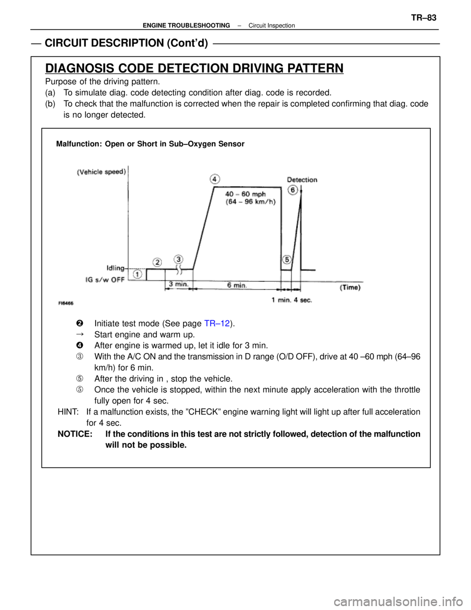
DIAGNOSIS CODE DETECTION DRIVING PATTERN
Purpose of the driving pattern.
(a) To simulate diag. code detecting condition after diag. code is recorded.
(b) To check that the malfunction is corrected when the repair is completed co\
nfirming that diag. codeis no longer detected.
Malfunction: Open or Short in Sub±Oxygen Sensor
�Initiate test mode (See page TR±12).
�Start engine and warm up.
�After engine is warmed up, let it idle for 3 min.
�With the A/C ON and the transmission in D range (O/D OFF), drive at 40 ±\
60 mph (64±96
km/h) for 6 min.
�After the driving in , stop the vehicle.
�Once the vehicle is stopped, within the next minute apply acceleration w\
ith the throttle
fully open for 4 sec.
HINT: If a malfunction exists, the ºCHECKº engine warning light will light\
up after full acceleration for 4 sec.
NOTICE: If the conditions in this test are not strictly followed, detection of the\
malfunction will not be possible.
±
ENGINE TROUBLESHOOTING Circuit InspectionTR±83
WhereEverybodyKnowsYourName
Page 3709 of 4087
DIAGNOSTIC CHART
DIAGNOSTIC
CHART
HINT:
wWhen other codes are output in addition to 27 and 29 at the same time, check the ci\
rcuits for other
codes first.
w If diag. code 27 is displayed, check left bank sub±oxygen sensor circ\
uit, and if 29 is displayed,
check right bank sub±oxygen sensor circuit.
WIRING DIAGRAM
Check voltage of terminals HTL2, HTR2.
Check resistance of sub±oxygen sensor heater.
Check and repair sub±oxygen sensor heater
circuit.
Check operation of sub±oxygen sensor heater.
Check and replace ECU. Replace main oxygen sensor.
*: In this case, oxygen sensor can be deteriorated.
Replace main oxygen sensor.*
TR±84±
ENGINE TROUBLESHOOTING Circuit Inspection
WhereEverybodyKnowsYourName
Page 3710 of 4087
NGOK
OKNG
INSPECTION PROCEDURE
1Disconnect the engine & ECT ECU connector.
C
OK
P(2) Connect the Check Harness A.(See page TR±30)
(2) Disconnect engine & ECT ECU connector.
(2) Turn ignition switch on.
Measure voltage between terminals HTL2, HTR2 of en-
gine & ECT ECU connector and body ground.
Voltage: 10 ± 14 V
Go to step [3].
2Check sub±oxygen sensor heater.
C
OK
PDisconnect sub±oxygen sensor connector.
Measure resistance between terminals 1 and 2 of sub±
oxygen sensor connector.
Resistance: 5.1 ± 6.3 � 20 �C (68 �F)
Replace sub±oxygen sensor.
Check and repair harness or connector between
main relay and sub±oxygen sensor, sub±oxygen
sensor and engine & ECT ECU.
±
ENGINE TROUBLESHOOTING Circuit InspectionTR±85
WhereEverybodyKnowsYourName
Page 3711 of 4087
NGOK
3Check voltage between terminals HTL2, HTR2 of engine & ECT ECU connector and \
body
ground.
C
OK
Hint
P(2) Connect engine & ECT ECU connector.
(2) Warm up engine to normal operating temperature.
Measure voltage between terminals HTL2, HTR2 of en-
gine & ECT ECU connector and body ground, when en-
gine is idling and racing at 4,000 rpm.
In the 4,000 rpm racing check , continue engine racing
at 4,000 prm for approx. 20 seconds or more.
Replace sub±oxygen sensor.**: In this case, oxygen sensor can be deteriorated.
Check and replace engine & ECT ECU.
TR±86±
ENGINE TROUBLESHOOTING Circuit Inspection
WhereEverybodyKnowsYourName
Page 3713 of 4087

Diag. Code 35
High Altitude Compensator Sensor
(HAC Sensor) Circuit
CIRCUIT DESCRIPTION
The HAC sensor is built into the ECU. This is a semiconductor pressure sens\
or with properties which
cause its electrical resistance to change when stress is applied to the senso\
r's crystal (silicon) (piezo-
electric effect). This sensor is used to detect the atmospheric (absolute) press\
ure and outputs corre-
sponding electrical signals. Fluctuations in the air pressure cause changes in t\
he intake air density,
which can cause deviations in the air±fuel ratio. The signals from HAC sen\
sor are used to make correc-
tions for these fluctuations. If the ECU records diagnostic code º35º\
, the fail safe function operates and
the atmospheric pressure is set at a constant 101.3 kPa (760 mmHg, 29.92 i\
n.Hg).
Code No.Diagnostic Code Detecting ConditionTrouble Area
35Open or short in HAC sensor circuit for
0.5 sec. or more. ECU
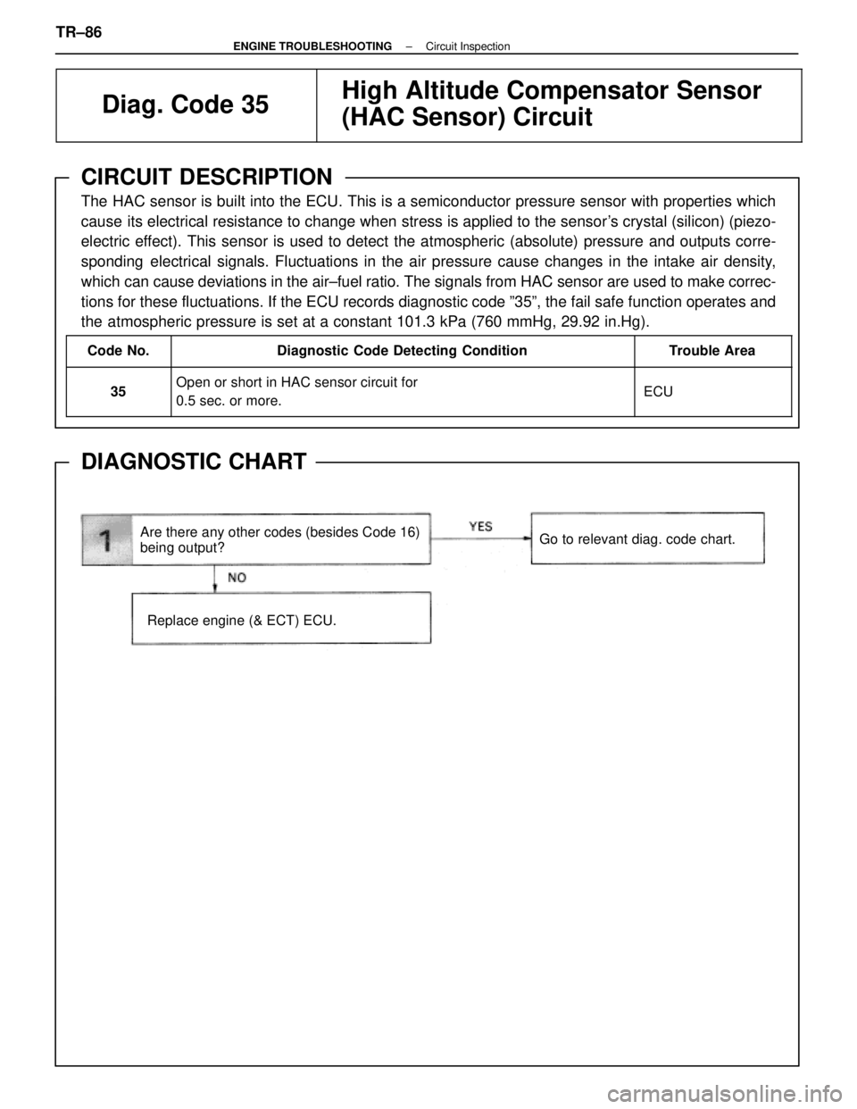
DIAGNOSTIC CHART
Are there any other codes (besides Code 16)
being output?
Replace engine (& ECT) ECU.
Go to relevant diag. code chart.
TR±86±
ENGINE TROUBLESHOOTING Circuit Inspection
WhereEverybodyKnowsYourName
Page 3718 of 4087

Diag. Code 35High Altitude Compensator Sensor
(HAC Sensor) Circuit
CIRCUIT DESCRIPTION
The HAC sensor is built into the ECU. This is a semiconductor pressure sens\
or with properties which cause its
electrical resistance to change when stress is applied to the sensor's crystal (silicon) (piezoelectric effect). This
sensor is used to detect the atmospheric (absolute) pressure and outputs cor\
responding electrical signals. Fluc-
tuations in the air pressure cause changes in the intake air density, which can cause deviations in the air±fuel
ratio. The signals from HAC sensor are used to make corrections for these fluct\
uations. If the ECU records diag-
nostic code º35º, the fail safe function operates and the atmospheric pressure is set at a\
constant 760 mmHg.
Code No.Diagnostic Code Detecting ConditionTrouble Area
35Open or short detected in HAC sensor circuit for 0.5
sec. or more.� ECU
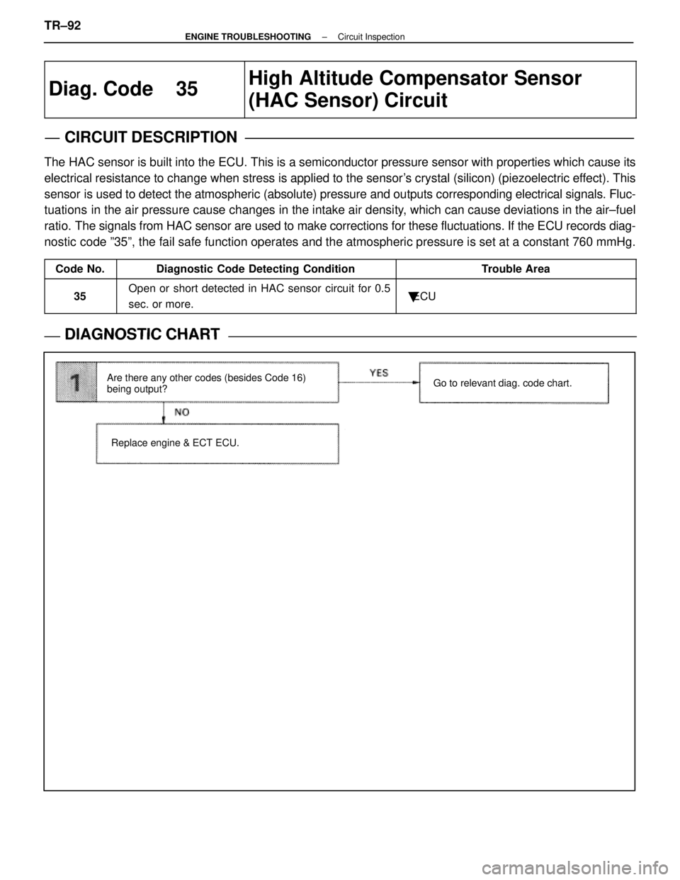
DIAGNOSTIC CHARTDIAGNOSTIC CHART
Are there any other codes (besides Code 16)
being output?
Replace engine & ECT ECU. Go to relevant diag. code chart.
TR±92±
ENGINE TROUBLESHOOTING Circuit Inspection
WhereEverybodyKnowsYourName
Page 3720 of 4087

Diag. Code 41, 47(Sub±) Throttle Position Sensor Circuit
CIRCUIT DESCRIPTION
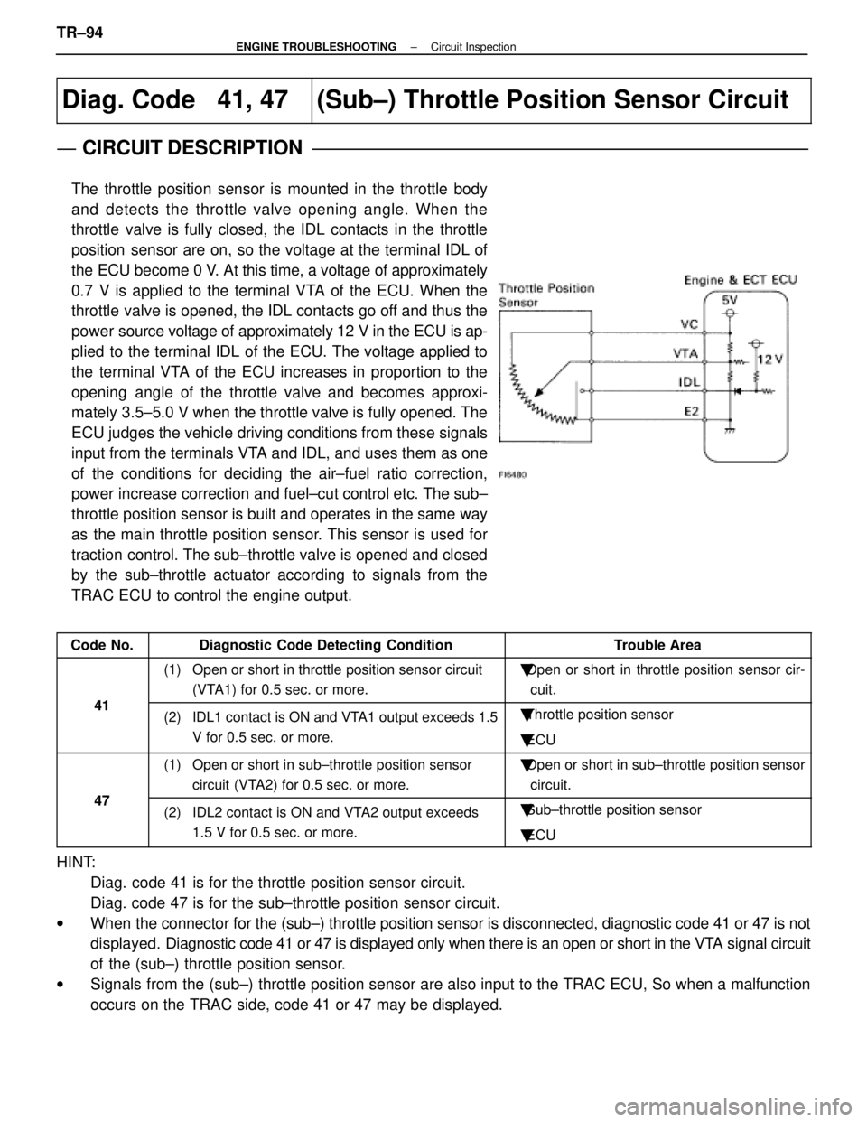
The throttle position sensor is mounted in the throttle body
and detects the throttle valve opening angle. When the
throttle valve is fully closed, the IDL contacts in the throttle
position sensor are on, so the voltage at the terminal IDL of
the ECU become 0 V. At this time, a voltage of approximately
0.7 V is applied to the terminal VTA of the ECU. When the
throttle valve is opened, the IDL contacts go off and thus the
power source voltage of approximately 12 V in the ECU is ap-
plied to the terminal IDL of the ECU. The voltage applied to
the terminal VTA of the ECU increases in proportion to the
opening angle of the throttle valve and becomes approxi-
mately 3.5±5.0 V when the throttle valve is fully opened. The
ECU judges the vehicle driving conditions from these signals
input from the terminals VTA and IDL, and uses them as one
of the conditions for deciding the air±fuel ratio correction,
power increase correction and fuel±cut control etc. The sub±
throttle position sensor is built and operates in the same way
as the main throttle position sensor. This sensor is used for
traction control. The sub±throttle valve is opened and closed
by the sub±throttle actuator according to signals from the
TRAC ECU to control the engine output.
Code No.Diagnostic Code Detecting ConditionTrouble Area
41
(1) Open or short in throttle position sensor circuit(VTA1) for 0.5 sec. or more.�Open or short in throttle position sensor cir-
cuit.
41(2) IDL1 contact is ON and VTA1 output exceeds 1.5 V for 0.5 sec. or more.�Throttle position sensor
� ECU
47
(1) Open or short in sub±throttle position sensor
circuit (VTA2) for 0.5 sec. or more.�Open or short in sub±throttle position sensor
circuit.
47(2) IDL2 contact is ON and VTA2 output exceeds 1.5 V for 0.5 sec. or more.�Sub±throttle position sensor
� ECU
HINT:
Diag. code 41 is for the throttle position sensor circuit.
Diag. code 47 is for the sub±throttle position sensor circuit.
w When the connector for the (sub±) throttle position sensor is disconnec\
ted, diagnostic code 41 or 47 is not
displayed. Diagnostic code 41 or 47 is displayed only when there is an open or short in the VTA signal circuit
of the (sub±) throttle position sensor.
w Signals from the (sub±) throttle position sensor are also input to the TRAC ECU, So when a malfu\
nction
occurs on the TRAC side, code 41 or 47 may be displayed.
TR±94
±
ENGINE TROUBLESHOOTING Circuit Inspection
WhereEverybodyKnowsYourName