Page 1461 of 4087
30. REMOVE OIL DIPSTICK AND GUIDE FORTRANSMISSION
(a) Remove the bolt holding the oil dipstick to the LH cylinder head.
(b) Pull out the dipstick guide together with the dipstick from the oil pan.
(c) Remove the O±ring from the dipstick guide.
31. REMOVE OIL DIPSTICK AND GUIDE FOR ENGINE
32. REMOVE EGR PIPE
(a) Remove the 2 bolts holding the EGR pipe to the RH exhaust pipe.
(b) Remove the EGR pipe and gasket.
33. DISCONNECT ENGINE WIRE FROM CYLINDER HEADS
(a) Remove the 2 bolts, and disconnect the engine wire protector
from the RH cylinder head.
(b) Remove the bolt, and disconnect the ground strap from the RH cylinder head.
(c) Remove the 5 bolts, and disconnect the engine wire protector
from the LH cylinder head.
34. REMOVE ENGINE HANGERS Remove the 2 bolts and engine hanger. Remove the 2 engine
hangers.
±
1UZ±FE ENGINE ENGINE MECHANICALEG±85
WhereEverybodyKnowsYourName
Page 1463 of 4087
(d) Alternately loosen and remove the 2 bearing cap boltsholding the intake camshaft side of the oil feed pipe to the
cylinder head.
(e) Uniformly loosen and remove the 8 bearing cap bolts in several passes, in the sequence shown.
(f) Remove the oil feed pipe, 4 bearing caps and ex haust
camshaft.
B. Remove intake camshaft from RH cylinder head
(a) Remove the rear bearing cap.
(b) Set the timing mark (1 dot mark) of the camshaft drive gear at approx. 45 � angle by turning the hexagon wrench head
portion of the intake camshaft with a wrench.
(c) Uniformly loosen and remove the 8 bearing cap bolts in several passes, in the sequence shown.
(d) Remove the 4 bearing caps, oil seal and intake camshaft.
±
1UZ±FE ENGINE ENGINE MECHANICALEG±87
WhereEverybodyKnowsYourName
Page 1464 of 4087
 Boring the service bolt hole of the driven sub±gear upwardby turning the hexagon wrench head portion of the exhaust
camshaft with a wrench.
(b)")
C. Remove exhaust camshaft from LH cylinder head
(a) Boring the service bolt hole of the driven sub±gear upwardby turning the hexagon wrench head portion of the exhaust
camshaft with a wrench.
(b) Secure the exhaust camshaft sub±gear to drive gear with a service bolt.
Recommended service bolt:6 mm for thread diameter
1.0 mm for thread pitch
16 ± 20 mm (0.63 ± 0.79 in.) for bolt length
HINT: When removing the camshaft, make sure that the tor-
sional spring force of the sub±gear has been eliminated by
the above operation.
(c) Set the timing mark (2 dot marks) of the camshaft drive gear at approx. 15 � angle by turning the hexagon wrench head
portion of the exhaust camshaft with a wrench.
(d) Alternately loosen and remove the 2 bearing cap bolts holding the intake camshaft side of the oil feed pipe to the
cylinder head.
(e) Uniformly loosen and remove the 8 bearing cap bolts in several passes, in the sequence shown.
(f) Remove the oil feed pipe, 4 bearing caps and ex haust
camshaft.
EG±88
±
1UZ±FE ENGINE ENGINE MECHANICAL
WhereEverybodyKnowsYourName
Page 1465 of 4087
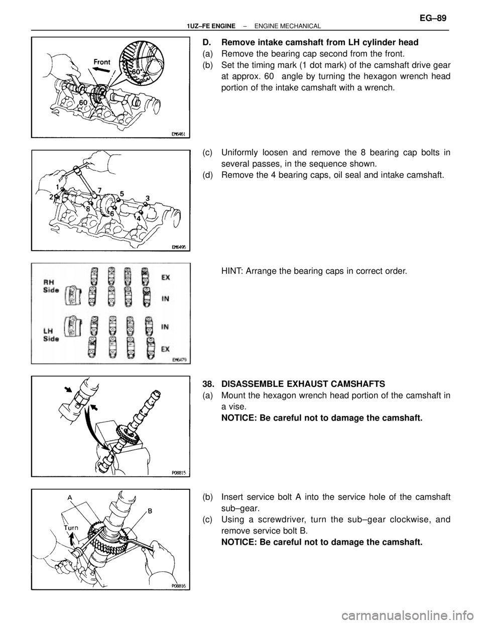
D. Remove intake camshaft from LH cylinder head
(a) Remove the bearing cap second from the front.
(b) Set the timing mark (1 dot mark) of the camshaft drive gearat approx. 60 � angle by turning the hexagon wrench head
portion of the intake camshaft with a wrench.
(c) Uniformly loosen and remove the 8 bearing cap bolts in several passes, in the sequence shown.
(d) Remove the 4 bearing caps, oil seal and intake camshaft.
HINT: Arrange the bearing caps in correct order.
38. DISASSEMBLE EXHAUST CAMSHAFTS
(a) Mount the hexagon wrench head portion of the camshaft in a vise.
NOTICE: Be careful not to damage the camshaft.
(b) Insert service bolt A into the service hole of the camshaft sub±gear.
(c) Using a screwdriver, turn the sub±gear clockwise, and
remove service bolt B.
NOTICE: Be careful not to damage the camshaft.
±
1UZ±FE ENGINE ENGINE MECHANICALEG±89
WhereEverybodyKnowsYourName
Page 1467 of 4087
40. DISCONNECT MAIN HEATED OXYGEN SENSORCONNECTORS
Disconnect the RH and LH oxygen sensor connectors.
41. REMOVE CYLINDER HEADS
(a) Uniformly loosen the ten cylinder head bolts one side of each
cylinder head in several passes, in the sequence shown,
then do the other side as shown. Remove the 20 cylinder
head bolts and plate washers.
NOTICE:
w Cylinder head warpage or cracking could result from
removing bolts in incorrect order.
w Do not drop the plate washer for cylinder head bolt into
portion A of the cylinder head. If dropped into portion A,
the plate washer will pass through the cylinder head and
cylinder block into the oil pan.
±
1UZ±FE ENGINE ENGINE MECHANICALEG±91
WhereEverybodyKnowsYourName
Page 1470 of 4087
(b) Remove the following parts:(1) Spring retainer
(2) Valve spring
(3) Valve
(4) Spring seat
HINT: Arrange the valves, valve springs, spring seats and
spring retainers incorrect order.
(c) Using needle±nose pliers, remove the oil seal.
EG±94
±
1UZ±FE ENGINE ENGINE MECHANICAL
WhereEverybodyKnowsYourName
Page 1471 of 4087
 Turn the crankshaft, and bring each piston to top dead center (TDC). Using a gasket s")
EG1KM±02
CYLINDER HEAD COMPONENTS
INSPECTION AND REPAIR
1. CLEAN TOP SURFACES OF PISTONS AND CYLINDERBLOCK
(a) Turn the crankshaft, and bring each piston to top dead center (TDC). Using a gasket scraper, remove all the carbon from
the piston top surface.
(b) Using a gasket scraper, remove all the gasket material from the cylinder block surface.
(c) Using compressed air, blow carbon and oil from the bolt
holes.
CAUTION: Protect your eyes when using high±compressed
air.
2. CLEAN CYLINDER HEAD
A. Remove gasket materialUsing a gasket scraper, remove all the gasket material from
the cylinder block contact surface.
NOTICE: Be careful not to scratch the cylinder block contact
surface.
B. Clean combustion chambers
Using a wire brush, remove all the carbon from the combus-
tion chambers.
NOTICE: Be careful not to scracth the cylinder block contact
surface.
C. Clean valve guide bushingsUsing a valve guide bushing brush and solvent, clean all the
guide bushings.
±
1UZ±FE ENGINE ENGINE MECHANICALEG±95
WhereEverybodyKnowsYourName
Page 1473 of 4087
 Using a caliper gauge, measure the inside diameter of theguide bushing.
Bushing inside diameter:
6.010 ± 6.030 mm (0.2366 ± 0.2374 in.)
(b) Using a")
5. INSPECT VALVE STEMS AND GUIDE BUSHINGS
(a) Using a caliper gauge, measure the inside diameter of theguide bushing.
Bushing inside diameter:
6.010 ± 6.030 mm (0.2366 ± 0.2374 in.)
(b) Using a micrometer, measure the diameter of the valve stem.
Valve stem diameter:
Intake5.970 ± 5.985 mm (0.2350 ± 0.2356 in.)
Exhaust 5.965 ± 5.980 mm (0.2348 ± 0.2354 in.)
(c) Subtract the valve stem diameter measurement from the guide bushing inside diameter measurement
Standard oil clearance:
Intake0.025 ± 0.060 mm (0.0010 ± 0.0024 in.)
Exhaust 0.030 ± 0.065 mm (0.0012 ± 0.0026 in.)
Maximum oil clearance: Intake
0.08 mm (0.0031 in.)
Exhaust 0.10 mm (0.0039 in.)
If the clearance is greater than maximum, replace the valve
and guide bushing.
6. IF NECESSARY, REPLACE VALVE GUIDE BUSHINGS
(a) Insert an old valve wrapped with tape into the valve guide bushing, and break off the valve guide bushing by hitting it
with a hammer. Remove the snap ring.
HINT: Wrap the tape approx. 8 mm (0.31 in.) from the valve
stem ends.
NOTICE: Be careful not to damage the valve lifter hole.
±
1UZ±FE ENGINE ENGINE MECHANICALEG±97
WhereEverybodyKnowsYourName
 Remove the bolt holding the oil dipstick to the LH cylinder head.
(b) Pull out the dipstick guide together with the dipstick from the oil")
 Alternately loosen and remove the 2 bearing cap boltsholding the intake camshaft side of the oil feed pipe to the
cylinder head.
(e) Uniformly loosen and remove the 8 bearing cap bolts in sever")
 Uniformly loosen the ten cylinder head bolts one side of each
c")
 Remove the following parts:(1) Spring retainer
(2) Valve spring
(3) Valve
(4) Spring seat
HINT: Arrange the valves, valve springs, spring seats and
spring retainers incorrect order.
(c) Using n")