Page 3655 of 4087
OKNG
INSPECTION PROCEDURE
1Check engine speed sensor, No. 1, No. 2 cam position sensor
C
OK
PFor engine speed sensor.
(2) Remove engine under cover.
(2) Disconnected engine speed sensor connector.
For No.1, No. 2 cam position sensor,
(2) Disconnect No. 1, No. 2 cam poisition sensor con-nectors.
Measure resistance of engine speed sencor, No. 1 and
No. 2 cam position sensor.
Replace engine speed sensor, No. 1, No. 2 cam poistion
sensor.
TR±50
±
ENGINE TROUBLESHOOTING Circuit Inspection
WhereEverybodyKnowsYourName
Page 3656 of 4087
OKNG
OKNG
2Check for open and short in harness and connector between engine & ECT ECU an\
d each sen-
sor (See page IN±27).
Repair or replace harness or connector.
3Inspect sensor installation and teeth of signal plate.
Tighen the sensor.
Replace signal plate.
Check and replace engine and ECT ECU.
±
ENGINE TROUBLESHOOTING Circuit InspectionTR±51
WhereEverybodyKnowsYourName
Page 3657 of 4087

Diag. Code 13RPM Signal Circuit (No. 2)
CIRCUIT DESCRIPTION
Refer to RPM signal circuit (No. 1) on page TR±46.
Code No.Diagnostic Code Detecting ConditionTrouble Area
13
No NE signal to ECU for 0.1 sec. or more at
1,000 rpm or more.
�Open or short in NE circuit
�Distributor13
No 12 pulses of NE to ECU during the interval
�Distributor
� ECU
No 12 ulses of NE to ECU during the interval
between G1 and G2 pulses.
�ECU
DIAGNOSTIC CHART
This code indicates that a momentary interruption of the RPM signal from the\
distributor to the ECU has
occurred, but that it is returned to normal. Note that although this problem may \
not necessarily appear
at the time of inspection, it cannot be ignored because this diagnostic co\
de is output, indicating that there
is or was a malfunction in the RPM signal circuit; this ºmalfunctionº\
is usually a loose connector.
The distributor connector and the NE terminal of the ECU connector must the\
refore be checked for the
following:
1. Loose connectors
2. Dirty connector terminals
3. Loose connector terminals
TR±50±
ENGINE TROUBLESHOOTING Circuit Inspection
WhereEverybodyKnowsYourName
Page 3658 of 4087

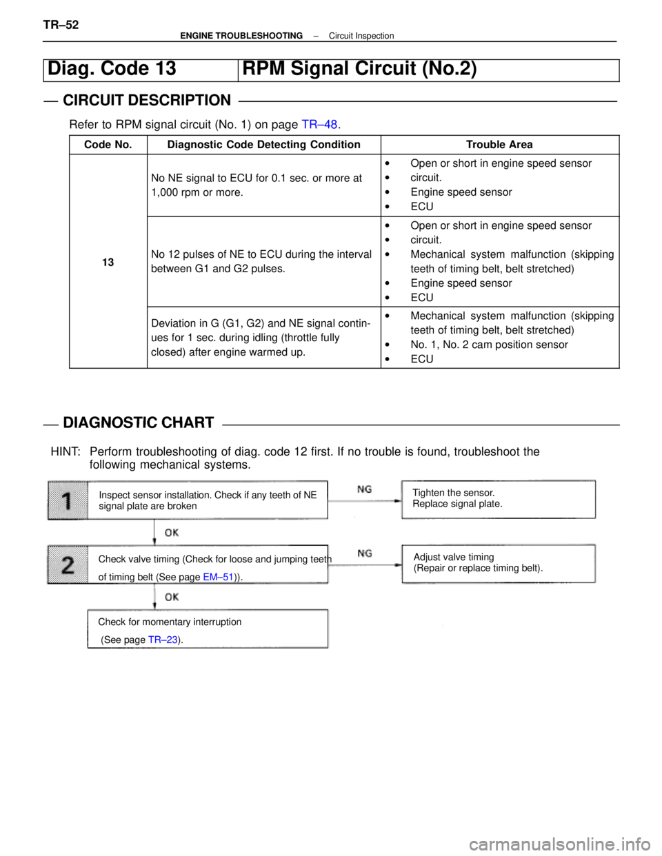
Diag. Code 13RPM Signal Circuit (No.2)
CIRCUIT DESCRIPTION
Refer to RPM signal circuit (No. 1) on page TR±48.
Code No.Diagnostic Code Detecting ConditionTrouble Area
No NE signal to ECU for 0.1 sec. or more at
1,000 rpm or more.
wOpen or short in engine speed sensor
w circuit.
w Engine speed sensor
w ECU
13No 12 pulses of NE to ECU during the interval
between G1 and G2 pulses.
wOpen or short in engine speed sensor
w circuit.
w Mechanical system malfunction (skipping
teeth of timing belt, belt stretched)
w Engine speed sensor
w ECU
Deviation in G (G1, G2) and NE signal contin-
ues for 1 sec. during idling (throttle fully
closed) after engine warmed up.wMechanical system malfunction (skipping
teeth of timing belt, belt stretched)
w No. 1, No. 2 cam position sensor
w ECU
DIAGNOSTIC CHARTDIAGNOSTIC CHART
Inspect sensor installation. Check if any teeth of NE
signal plate are broken
Check valve timing (Check for loose and jumping teeth
of timing belt (See page EM±51)). Tighten the sensor.
Replace signal plate.
Adjust valve timing
(Repair or replace timing belt).
HINT: Perform troubleshooting of diag. code 12 first. If no trouble is found, trouble\
shoot the following mechanical systems.
Check for momentary interruption
(See page TR±23).
TR±52±
ENGINE TROUBLESHOOTING Circuit Inspection
WhereEverybodyKnowsYourName
Page 3661 of 4087

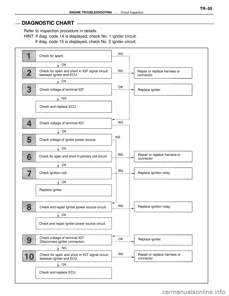
DIAGNOSTIC CHART
DIAGNOSTIC
CHART
Refer to inspection procedure in details.
HINT: If diag. code 14 is displayed, check No. 1 igniter circuit. If diag. code 15 is displayed, check No. 2 igniter circuit.
Check for spark.
Check for open and short in IGF signal circuit
between igniter and ECU.
Check voltage of terminal IGF.
Check and replace ECU.
Check voltage of terminal IGT.
Check voltage of igniter power source.
Check for open and short in primary coil circuit.
Check ignition coil.
Replace igniter.
Check and repair igniter power source circuit.
Check voltage of terminal IGT
(Disconnect igniter connector).
Check and repair igniter power source circuit. Repair or replace harness or
connector.
Replace igniter.
Repair or replace harness or
connector
Replace ignition relay.
Replace ignition relay.
Check for open and short in IGT signal circuit
between igniter and ECU.
Check and replace ECU. Repair or replace harness or
connectorReplace igniter.
±
ENGINE TROUBLESHOOTING Circuit InspectionTR±55
WhereEverybodyKnowsYourName
Page 3662 of 4087

OKNG
OKNG
OKNG
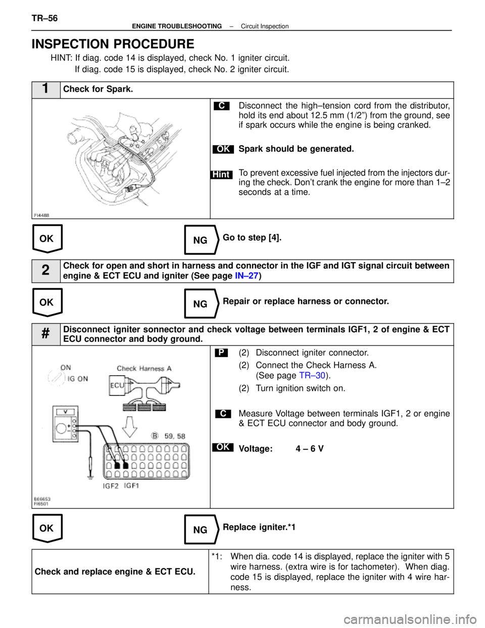
INSPECTION PROCEDURE
HINT: If diag. code 14 is displayed, check No. 1 igniter circuit. If diag. code 15 is displayed, check No. 2 igniter circuit.
1Check for Spark.
C
OK
Hint
Disconnect the high±tension cord from the distributor,
hold its end about 12.5 mm (1/2º) from the ground, see
if spark occurs while the engine is being cranked.
Spark should be generated.
To prevent excessive fuel injected from the injectors dur-
ing the check. Don't crank the engine for more than 1±2
seconds at a time.
Go to step [4].
2Check for open and short in harness and connector in the IGF and IGT signal c\
ircuit between
engine & ECT ECU and igniter (See page IN±27)
Repair or replace harness or connector.
#Disconnect igniter sonnector and check voltage between terminals IGF1, 2 of engine & ECT
ECU connector and body ground.
C
OK
P(2) Disconnect igniter connector.
(2) Connect the Check Harness A.
(See page TR±30).
(2) Turn ignition switch on.
Measure Voltage between terminals IGF1, 2 or engine
& ECT ECU connector and body ground.
Voltage: 4 ± 6 V
Replace igniter.*1
Check and replace engine & ECT ECU.
*1: When dia. code 14 is displayed, replace the igniter with 5 wire harness. (extra wire is for tachometer). When diag.
code 15 is displayed, replace the igniter with 4 wire har-
ness.
TR±56±
ENGINE TROUBLESHOOTING Circuit Inspection
WhereEverybodyKnowsYourName
Page 3663 of 4087
OKNG
OKNG
4Check voltage between terminals IGT1, 2 of engine and & ECT ECU connector and body ground.
C
OK
PConnect the Check Harness A.
(See page TR±30).
Measure voltage between terminals IGT1, 2 of engine
& ECT ECU connector and body ground when engine
is cranked.
Voltage: 0.5 ± 1.0 V (Neither 0 V nor 5 V)
Go to step [9].
5Check voltage between terminal 3 of No. 1, No. 2 igniter connectors and \
body ground.
C
OK
PDisconnect igniter connector.
Mesure voltage between terminal 3 of No. 1, No. 2 igni-
ter connectors and body ground, when ignitino switch is
turned to ªONº and ªSTAº position.
Voltage: 10 ± 14 V
Go to step [8].
±
ENGINE TROUBLESHOOTING Circuit InspectionTR±57
WhereEverybodyKnowsYourName
Page 3664 of 4087
OKNG
OKNG
6Check for open and short in harness and connector between ignition relay and \
ignition coil,
ignition coil and igniter (See page IN±27).
Repair or replace harness or connector
#Check ignition coil.
C
OK
PDisconnect ignition coil connector.
(For No. 1 ignition coil (on left bank), remove the battery)
(2) Check primary coil. Measure resistance between terminals of ignition
coil connector.
(2) Check secondary coil. Measure resistance between terminal 1 of ignition
coil connector and high±tension terminal.
Replace ignition coil.
Replace Igniter. *1
*1: When diag. code 14 is displayed, replace the igniter with 5 wire harness. (extra wire is for tachometer). When diag.
code 15 is displayed, replace the igniter with 4 wire har-
ness
TR±58±
ENGINE TROUBLESHOOTING Circuit Inspection
WhereEverybodyKnowsYourName