Page 3612 of 4087

FAIL±SAFE CHART
If any of the following codes is recorded, the ECU enters fail±safe mod\
e.
Code No.Fail±Safe OperationFail±Safe Deactivation Conditions
14Fuel cut1 IGF detected in consecutive 3 ignitions.
16Torque control prohibited.Returned to normal condition.
22THW is fixed at 805C (176 5F).Returned to normal condition.
24THA is fixed at 20 5C (68 5F).Returned to normal condition.
31� Ignition timing fixed at 10 5 BTDC.
� Injection time fixed
Starting 9 m sec.KS input 15 times/sec. or more.
IDL ON 3.6 m sec.
IDL OFF 6.7 m sec.
35Atmospheric pressure is fixed at 101.3 kPa
(760 mmHg 29 92 in Hg)
Returned to normal condition.
(760 mmHg, 29.92 in.Hg).
41VTA1 is fixed at 05.The following must each be repeated at least 241VTA1 is fixed at 0 5.The following must each be re eated at least 2
time consecutively.time consecutively.
(w/o TRAC)(w/o TRAC)
� 0.1 V ? VTA ? 0.95 V 0.1 V ? VTA ? 0.95 V
�� IDL : ON
( / TRAC)(w/ TRAC)
025V?VTA?095V � 0.25 V ? VTA ? 0.95 V
� IDL:ON � IDL : ON
52Max. timing retardation.IG switch OFF.
53Max. timing retardation.Returned to normal condition.
55Max. timing retardation.IG switch OFF.
Back±Up Function
If there is trouble with the program in the ECU and the ignition signals\
(IGT) are not output, the ECU controls
fuel injection and ignition timing at predetermined levels as a back±up f\
unction to make it possible to continue
to operate the vehicle.
Furthermore, the injection duration is calculated from the starting sign\
al (STA) and the throttle position signal
(IDL). Also, the ignition timing is fixed at the initial ignition timing, 10 5 BTDC, without relation to the engine speed.
HINT: If the engine is controlled by the back±up function, the ºCHECKº\
engine warning light lights up to warn
the driver of the malfunction but the diagnostic code is not output. TR±26
±
ENGINE TROUBLESHOOTING Fail±Safe Chart
WhereEverybodyKnowsYourName
Page 3616 of 4087

TERMINALS OF ECU
Connectors of the engine & ECT ECU are water±proof and are the
bolt type.
For water proof type connectors, in order to measure the voltage
of ECU terminals and the resistance of connected parts, connect
the inspection sub wire harness between the ECU and vehicle
wire harness, then perform the inspection. The inspection method
of inserting a tester probe from the other side of connector notice-
ably reduces the water±proof ability.
Disconnect the connector by fully loosening the bolt.
PREPARATION
1. Turn the ignition switch to LOCK position.
2. Turn up the passenger side floor mat.
3. Remove the ECU protector.
4. Disconnect the connector from the ECU. After completely loosening the bolt, the two parts of the con-
nector can be separated.
NOTICE:
w Do not pully the wire harness when disconnecting the
connector.
w When disconnecting the connector, the ECU's backup
power source is cut off, so the malfunction codes, etc.
recorded in the ECU memory are cancelled.
w Never insert a tester probe or male terminal used for
inspection purposes into the female terminal of the
vehicle wire harness. Otherwise, the female terminal may
be widened, which can result in faulty connection.
5. Connect the Check Harness A between ECU and connector
of vehicle wire harness.
SST 09990±01000
HINT: The arrangement of the check connector terminals are
the same as those of the ECU.
See page TR±31
6. Disconnect the Check Harness A.
7. Reconnect the connector to the ECU.
(a) Match the male connector correctly with the femaleconnector, then press them together.
(b) Tighten the bolt Make sure the connector is completely connected, by
tightening the bolt until there is a clearance of less than
1 mm (0.04 in.) between bottom of the male connector
and end of the female connector.
8. Install the ECU protector and floor mat.
TR±30
±
ENGINE TROUBLESHOOTING Terminals of ECU
WhereEverybodyKnowsYourName
Page 3624 of 4087
 ECU are water±proof and
are the bolt type.
For water proof type connectors, in order to measure the volt-
age of ECU terminals and the resistance o")
TERMINALS OF ECU
Connectors of the engine (& ECT) ECU are water±proof and
are the bolt type.
For water proof type connectors, in order to measure the volt-
age of ECU terminals and the resistance of connected parts,
connect the inspection sub wire harness between the ECU
and vehicle wire harness, then perform the inspection.
The inspection method of inserting a tester probe from the
other side of connector noticeably reduces the water±proof
ability.
Disconnect the connector by fully loosening the bolt.
PREPARATION
1. Turn the ignition switch to LOCK position.
2. Turn up the passenger side floor mat.
3. Remove the ECU protector.
4. Disconnect the connector from the ECU.After completely loosening the bolt, the two parts of the con-
nector can be separated.
NOTICE:
w Do not pully the wire harness when disconnecting the
connector.
w When disconnecting the connector, the ECU's backup
power source is cut off, so the malfunction codes, etc.
recorded in the ECU memory are cancelled.
w Never insert a tester probe or male terminal used for
inspection purposes into the female terminal of the
vehicle wire harness. Otherwise, the female terminal may
be widened, which can result in faulty connection.
5. Connect the Check Harness A between ECU and
connector of vehicle wire harness.
SST 09990±01000
HINT: The arrangement of the check connector terminals are
the same as those of the ECU.
See page TR±35
6. Disconnect the Check Harness A.
7. Reconnect the connector to the ECU. (a) Match the male connector correctly with the femaleconnector, then press them together.
(b) Tighten the bolt
Make sure the connector is completely connected, by tight-
ening the bolt until there is a clearance of less than 1 mm
(0.04 in.) between bottom of the male connector and end of
the female connector.
8. Install the ECU protector and floor mat.
TR±34
±
ENGINE TROUBLESHOOTING Terminals of ECU
WhereEverybodyKnowsYourName
Page 3627 of 4087
TR±88
TR±10
0
TR±12
2
TR±13
0
TR±13
6
TR±14
0
TR±11
4
TR±14
2 TR±108
TR±11
8
TR±12
4
TR±13
2
AC±84
ST±24
IG±24 IG±6
EM±30
AT±66
IN±32BE±381IG±7
IG±9
MATRIX CHART OF PROBLEM SYMPTOMS
When the malfunction code is not confirmed in the diagnostic code check and \
the problem still can not be con-
firmed in the basic inspection, then proceed to this step and perform troubles\
hooting according to the numbered
order given in the table below.
The circuits indicated by on the matrix chart can be inspected using th\
e TCCS checker.
±
ENGINE TROUBLESHOOTING Martrix Chart of Problem SymptomsTR±35
WhereEverybodyKnowsYourName
Page 3642 of 4087
TR±82
TR±96
TR±104
TR±114
TR±118
TR±120
TR±126
TR±128
TR±132
TR±110
AC±68
ST±13 14
IG±6
IG±7
IG±10
IG±10
EM±22
AT±68
BE±398
IN±32
MATRIX CHART OF PROBLEM SYMPTOMS
When the malfunction code is not confirmed in the diagnostic trouble code ch\
eck and the problem still can not
be confirmed in the basic inspection, then proceed to this step and perfor\
m troubleshooting according to the
numbered order given in the table below.
The circuits indicated by on the matrix chart can be inspected using th\
e TCCS checker.
±
ENGINE TROUBLESHOOTING Matrix Chart of Problem SymptomsTR±39
WhereEverybodyKnowsYourName
Page 3650 of 4087
DIAGNOSTIC CHART
WIRING DIAGRAM
Check resistance of each pickup coils in
distributor
Check for open and short in harness and
connector between ECU and distributor.
Check air gap.
Check and replace ECU.
Replace distributor.
Repair or rep lace harness or connector.
Replace distributor
±
ENGINE TROUBLESHOOTING Circuit InspectionTR±47
WhereEverybodyKnowsYourName
Page 3651 of 4087
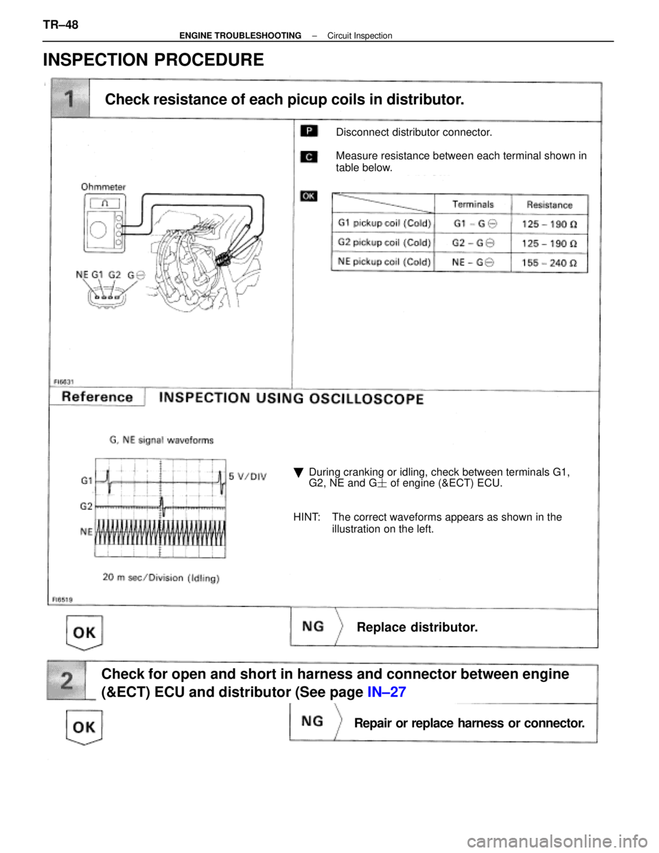
Disconnect distributor connector.
Measure resistance between each terminal shown in
table below.
Check resistance of each picup coils in distributor.
�During cranking or idling, check between terminals G1,
G2, NE and G � of engine (&ECT) ECU.
HINT: The correct waveforms appears as shown in the illustration on the left.
Replace distributor.
Check for open and short in harness and connector between engine
(&ECT) ECU and distributor (See page IN±27
Repair or replace harness or connector.
INSPECTION PROCEDURE
TR±48±
ENGINE TROUBLESHOOTING Circuit Inspection
WhereEverybodyKnowsYourName
Page 3652 of 4087
Remove distributor cap & rotor.
Using SST (G1 and G2 pickups) and a thikness gauge
(NE pickup). measure the air gap between the signal
rotor projection and pickup coil.
SST 09240±00020 fro G1 and G2 pickups
Air gap: 0.2±0.4 mm (0.008±0.016 in.)
Replace distributor.
Check and replace engine (& ECT) ECU.
±
ENGINE TROUBLESHOOTING Circuit InspectionTR±49
WhereEverybodyKnowsYourName


 and a thikness gauge
(NE pickup). measure the air gap between the signal
rotor projection and pickup coil.
SST 09240±00020 fro G1 and G2")