Page 1808 of 4087
25. INSTALL ENGINE WIRE TO INTAKE MANIFOLDInstall the engine wire with the two bolts.
26. TEMPORARILY INSTALL EGR PIPE TO RH CYLINDER HEAD
Temporarily install a new gasket and the EGR pipe with the
two bolts.
HINT: Use bolt 25 mm (0.98 in.) in length.
27. CONNECT FUEL RETURN HOSE TO FUEL RETURN PIPE
28. CONNECT FUEL INLET HOSE TO LH DELIVERY PIPE Connect the inlet hose with two new gaskets and the pulsa-
tion damper.
SST 09612±24012 (09617±24011)
Torque: 39 N Vm (400 kgf Vcm, 29 ft Vlbf)
33 N Vm (340 kgf Vcm, 24 ft Vlbf) for SST
HINT: Use a torque wrench with a fulcrum length of 30 cm
(11.81 in.).
29. CONNECT HEATER WATER HOSES Connect the following hoses:(1) Water hose to water by±pass pipe
(2) Water hose to rear water by±pass joint
30. INSTALL AIR INTAKE CHAMBER (a) Install the cold start injector, tube and wire assemblywith the three bolts.
Torque: 7.8 N Vm (80 kgf Vcm, 69 in. Vlbf)
±
ENGINE MECHANICAL Cylinder HeadsEM±107
WhereEverybodyKnowsYourName
Page 1809 of 4087
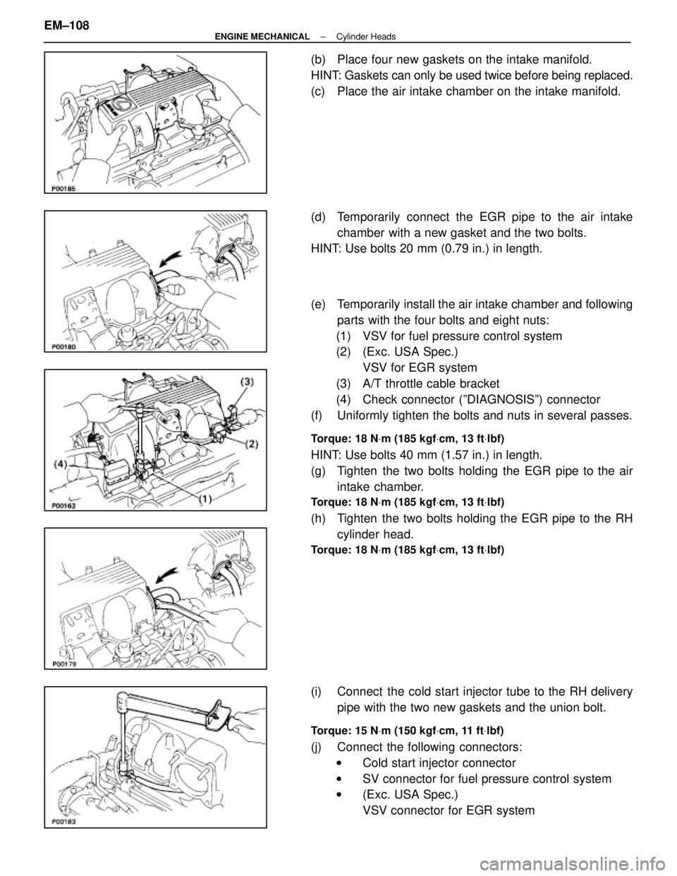
(b) Place four new gaskets on the intake manifold.
HINT: Gaskets can only be used twice before being replaced.
(c) Place the air intake chamber on the intake manifold.
(d) Temporarily connect the EGR pipe to the air intakechamber with a new gasket and the two bolts.
HINT: Use bolts 20 mm (0.79 in.) in length.
(e) Temporarily install the air intake chamber and following
parts with the four bolts and eight nuts:
(1) VSV for fuel pressure control system
(2) (Exc. USA Spec.) VSV for EGR system
(3) A/T throttle cable bracket
(4) Check connector (ºDIAGNOSISº) connector
(f) Uniformly tighten the bolts and nuts in several passes.
Torque: 18 N Vm (185 kgf Vcm, 13 ft Vlbf)
HINT: Use bolts 40 mm (1.57 in.) in length.
(g) Tighten the two bolts holding the EGR pipe to the air
intake chamber.
Torque: 18 N Vm (185 kgf Vcm, 13 ft Vlbf)
(h) Tighten the two bolts holding the EGR pipe to the RH
cylinder head.
Torque: 18 N Vm (185 kgf Vcm, 13 ft Vlbf)
(i) Connect the cold start injector tube to the RH delivery
pipe with the two new gaskets and the union bolt.
Torque: 15 N Vm (150 kgf Vcm, 11 ft Vlbf)
(j) Connect the following connectors:
w Cold start injector connector
w SV connector for fuel pressure control system
w (Exc. USA Spec.)
VSV connector for EGR system
EM±108
±
ENGINE MECHANICAL Cylinder Heads
WhereEverybodyKnowsYourName
Page 1810 of 4087
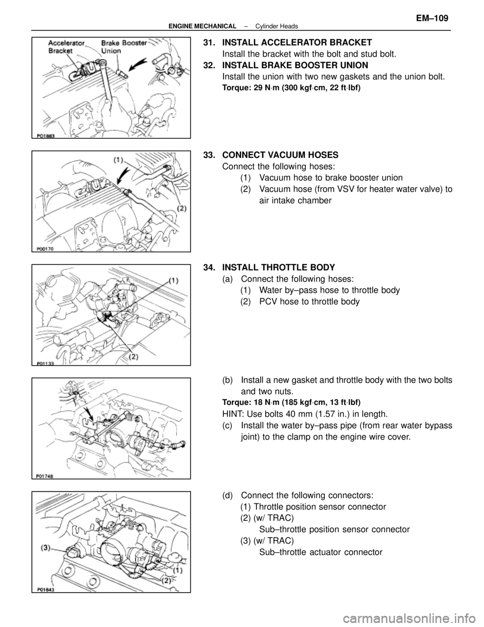
31. INSTALL ACCELERATOR BRACKETInstall the bracket with the bolt and stud bolt.
32. INSTALL BRAKE BOOSTER UNION Install the union with two new gaskets and the union bolt.
Torque: 29 N Vm (300 kgf Vcm, 22 ft Vlbf)
33. CONNECT VACUUM HOSES
Connect the following hoses:(1) Vacuum hose to brake booster union
(2) Vacuum hose (from VSV for heater water valve) to
air intake chamber
34. INSTALL THROTTLE BODY (a) Connect the following hoses:(1) Water by±pass hose to throttle body
(2) PCV hose to throttle body
(b) Install a new gasket and throttle body with the two bolts and two nuts.
Torque: 18 N Vm (185 kgf Vcm, 13 ft Vlbf)
HINT: Use bolts 40 mm (1.57 in.) in length.
(c) Install the water by±pass pipe (from rear water bypass
joint) to the clamp on the engine wire cover.
(d) Connect the following connectors: (1) Throttle position sensor connector
(2) (w/ TRAC) Sub±throttle position sensor connector
(3) (w/ TRAC) Sub±throttle actuator connector
±
ENGINE MECHANICAL Cylinder HeadsEM±109
WhereEverybodyKnowsYourName
Page 1811 of 4087
35. INSTALL HEATER WATER VALVE(a) Install the water valve and bracket assembly with thetwo bolts.
(b) Install the engine wire clamp with the bolt.
(c) Connect the VSV connector.
36. INSTALL ISC VALVE (a) Install a new gasket and the ISC valve with the two nuts.
Torque: 18 N Vm (185 kgf Vcm, 13 ft Vlbf)
(b) Connect the water by±pass hose (from throttle body) to
the ISC valve.
(c) Connect the ISC valve connector.
37. INSTALL EGR VALVE ADAPTOR (a) Install a new gasket, the adaptor and connector bracket(USA spec. only) with the two bolts and two nuts.
Torque: 18 N Vm (185 kgf Vcm, 13 ft Vlbf)
HINT: Use bolts 20 mm (1.79 in.) in length.
NOTICE: Do not touch the air intake chamber and adap-
tor surfaces of the gasket with your hand.
(b) Connect the PCV hose to cylinder head.
(c) (USA Spec. only)
Connect the EGR gas temperature sensor connector.
EM±110
±
ENGINE MECHANICAL Cylinder Heads
WhereEverybodyKnowsYourName
Page 1812 of 4087
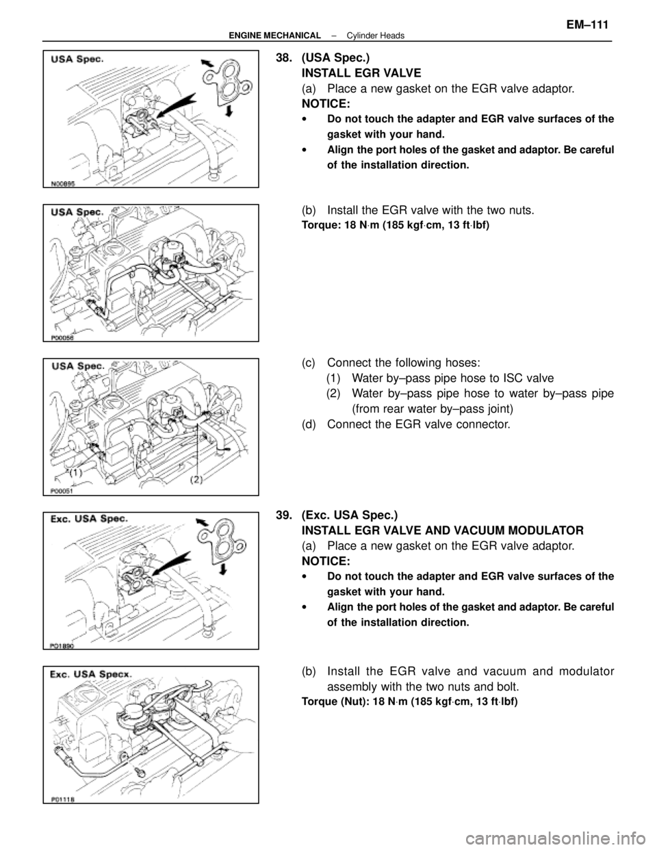
38. (USA Spec.)INSTALL EGR VALVE
(a) Place a new gasket on the EGR valve adaptor.
NOTICE:
w Do not touch the adapter and EGR valve surfaces of the
gasket with your hand.
w Align the port holes of the gasket and adaptor. Be careful
of the installation direction.
(b) Install the EGR valve with the two nuts.
Torque: 18 N Vm (185 kgf Vcm, 13 ft Vlbf)
(c) Connect the following hoses:
(1) Water by±pass pipe hose to ISC valve
(2) Water by±pass pipe hose to water by±pass pipe (from rear water by±pass joint)
(d) Connect the EGR valve connector.
39. (Exc. USA Spec.) INSTALL EGR VALVE AND VACUUM MODULATOR
(a) Place a new gasket on the EGR valve adaptor.
NOTICE:
w Do not touch the adapter and EGR valve surfaces of the
gasket with your hand.
w Align the port holes of the gasket and adaptor. Be careful
of the installation direction.
(b) Install the EGR valve and vacuum and m odulator
assembly with the two nuts and bolt.
Torque (Nut): 18 N Vm (185 kgf Vcm, 13 ft Vlbf)
±
ENGINE MECHANICAL Cylinder HeadsEM±111
WhereEverybodyKnowsYourName
Page 1813 of 4087
(c) Connect the following hoses:(1) Water by±pass pipe hose to ISC valve
(2) Water by±pass pipe hose to water by±pass pipe (from rear water by±pass joint)
(3) Two vacuum hoses to VSV for EGR system
40. INSTALL VACUUM PIPE (a) Install the vacuum pipe, vacuum hoses assembly andEGR water by±pass pipe (USA spec. only) with the two
bolts.
(b) Connect the following hoses: (1) (USA Spec.) Vacuum hose to throttle body
(2) (Exc. USA Spec.) Three vacuum hoses to throttle body
(3) Vacuum hose to fuel pressure regulator
(4) Two vacuum hoses to VSV for fuel pressure control system
(5) (Exc. USA Spec.) Two vacuum hoses to EGR vacuum modulator
(6) Two vacuum hoses (from VSV for EVAP system) to vacuum pipe
(7) Vacuum hose (from VSV for fuel pressure control system) to air intake chamber
(8) Vacuum hose (from charcoal canister) to vacuum pipe
EM±112
±
ENGINE MECHANICAL Cylinder Heads
WhereEverybodyKnowsYourName
Page 1814 of 4087
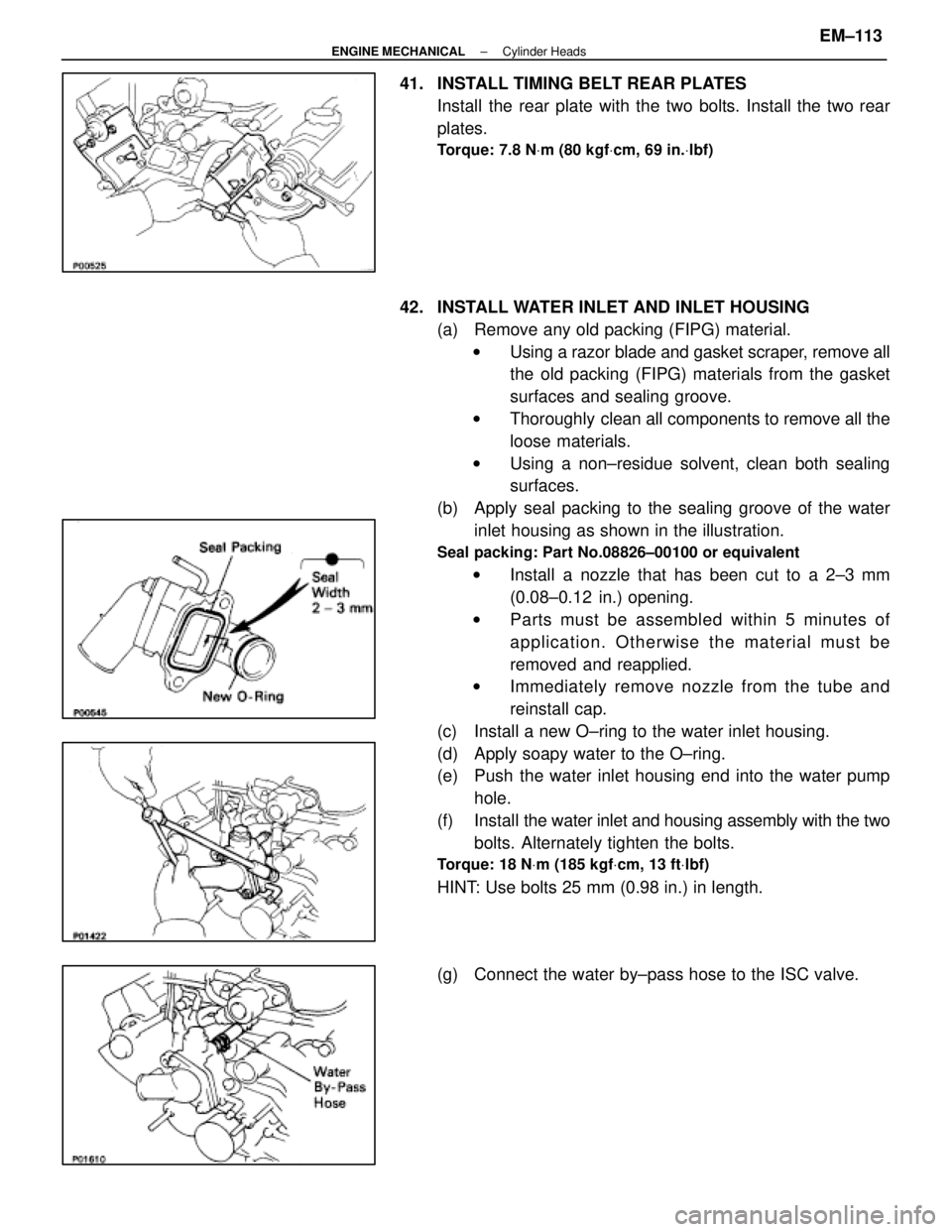
41. INSTALL TIMING BELT REAR PLATESInstall the rear plate with the two bolts. Install the two rear
plates.
Torque: 7.8 N Vm (80 kgf Vcm, 69 in. Vlbf)
42. INSTALL WATER INLET AND INLET HOUSING
(a) Remove any old packing (FIPG) material.w Using a razor blade and gasket scraper, remove all
the old packing (FIPG) materials from the gasket
surfaces and sealing groove.
w Thoroughly clean all components to remove all the
loose materials.
w Using a non±residue solvent, clean both sealing
surfaces.
(b) Apply seal packing to the sealing groove of the water inlet housing as shown in the illustration.
Seal packing: Part No.08826±00100 or equivalent
w Install a nozzle that has been cut to a 2±3 mm
(0.08±0.12 in.) opening.
w Parts must be assembled within 5 minutes of
application. Otherwise the material must be
removed and reapplied.
w Immediately remove nozzle from the tube and
reinstall cap.
(c) Install a new O±ring to the water inlet housing.
(d) Apply soapy water to the O±ring.
(e) Push the water inlet housing end into the water pump hole.
(f) Install the water inlet and housing assembly with the two
bolts. Alternately tighten the bolts.
Torque: 18 N Vm (185 kgf Vcm, 13 ft Vlbf)
HINT: Use bolts 25 mm (0.98 in.) in length.
(g) Connect the water by±pass hose to the ISC valve.
±
ENGINE MECHANICAL Cylinder HeadsEM±113
WhereEverybodyKnowsYourName
Page 1815 of 4087
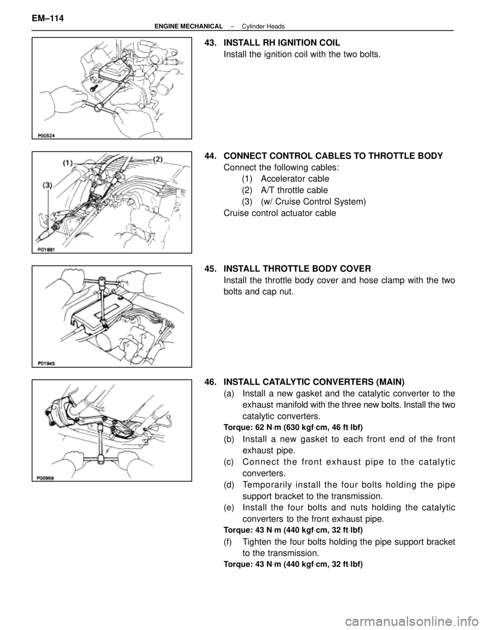
43. INSTALL RH IGNITION COILInstall the ignition coil with the two bolts.
44. CONNECT CONTROL CABLES TO THROTTLE BODY Connect the following cables:(1) Accelerator cable
(2) A/T throttle cable
(3) (w/ Cruise Control System)
Cruise control actuator cable
45. INSTALL THROTTLE BODY COVER Install the throttle body cover and hose clamp with the two
bolts and cap nut.
46. INSTALL CATALYTIC CONVERTERS (MAIN) (a) Install a new gasket and the catalytic converter to theexhaust manifold with the three new bolts. Install the two
catalytic converters.
Torque: 62 N Vm (630 kgf Vcm, 46 ft Vlbf)
(b) Install a new gasket to each front end of the front
exhaust pipe.
(c) C onnect the front exhaust pipe to the catalytic
converters.
(d) Te mp o ra rily in sta ll th e fo u r bo lts ho ld in g th e pip e support bracket to the transmission.
(e) Install the four bolts and nuts holding the catalytic
converters to the front exhaust pipe.
Torque: 43 N Vm (440 kgf Vcm, 32 ft Vlbf)
(f) Tighten the four bolts holding the pipe support bracket
to the transmission.
Torque: 43 N Vm (440 kgf Vcm, 32 ft Vlbf)
EM±114±
ENGINE MECHANICAL Cylinder Heads
WhereEverybodyKnowsYourName