Page 3449 of 4087

DIAGNOSTIC CHART
DIAGNOSTIC
CHART
Refer to inspection procedure in details.
HINT: If diag. code 14 is displayed, check No. 1 igniter circuit. If diag. code 15 is displayed, check No. 2 igniter circuit.
Check for spark.
Check for open and short in IGF signal circuit
between igniter and ECU.
Check voltage of terminal IGF.
Check and replace ECU.
Check voltage of terminal IGT.
Check voltage of igniter power source.
Check for open and short in primary coil circuit.
Check ignition coil.
Replace igniter.
Check and repair igniter power source circuit.
Check voltage of terminal IGT
(Disconnect igniter connector).
Check and repair igniter power source circuit. Repair or replace harness or
connector.
Replace igniter.
Repair or replace harness or
connector
Replace ignition relay.
Replace ignition relay.
Check for open and short in IGT signal circuit
between igniter and ECU.
Check and replace ECU. Repair or replace harness or
connectorReplace igniter.
±
ENGINE TROUBLESHOOTING Circuit InspectionTR±55
WhereEverybodyKnowsYourName
Page 3450 of 4087

OKNG
OKNG
OKNG
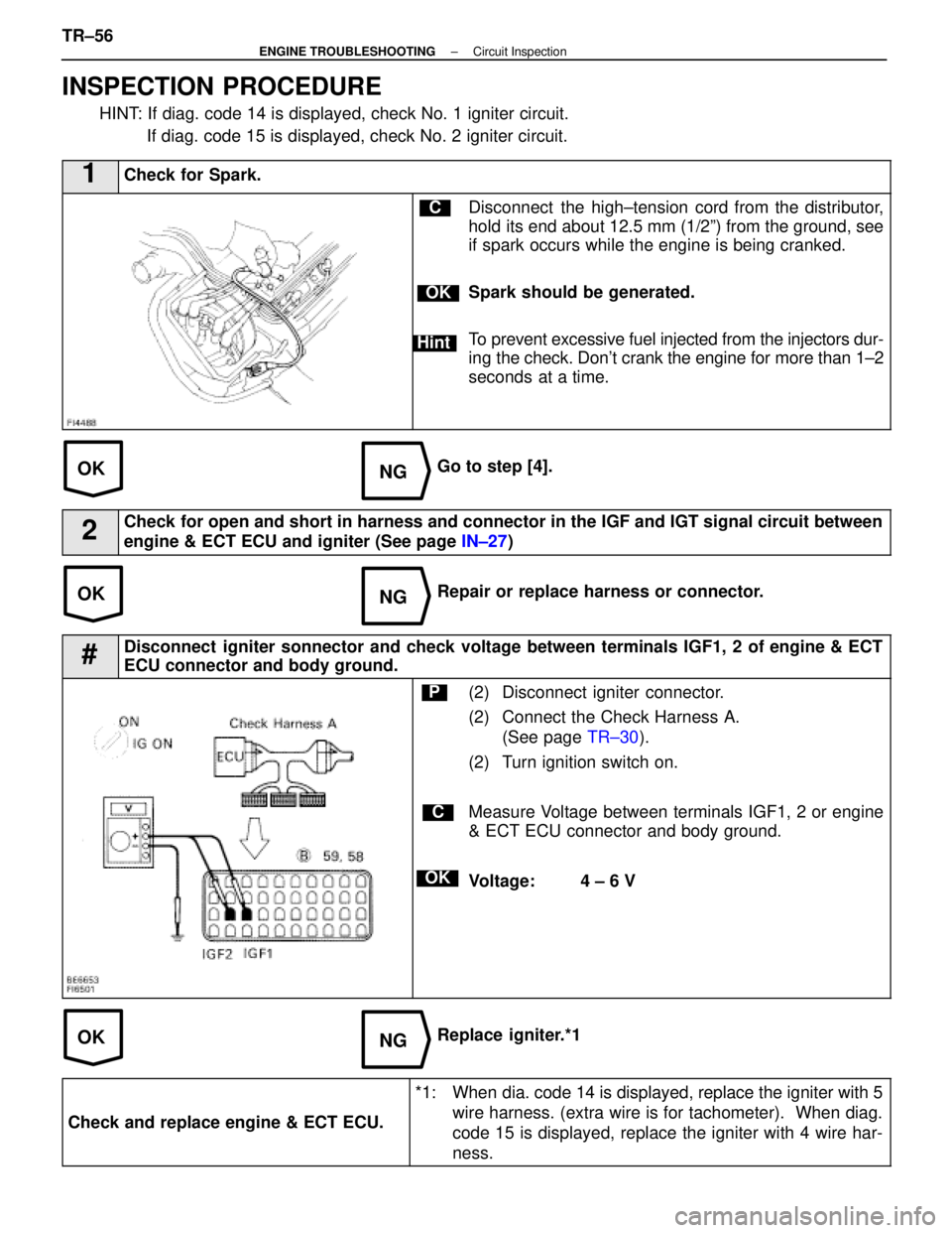
INSPECTION PROCEDURE
HINT: If diag. code 14 is displayed, check No. 1 igniter circuit. If diag. code 15 is displayed, check No. 2 igniter circuit.
1Check for Spark.
C
OK
Hint
Disconnect the high±tension cord from the distributor,
hold its end about 12.5 mm (1/2º) from the ground, see
if spark occurs while the engine is being cranked.
Spark should be generated.
To prevent excessive fuel injected from the injectors dur-
ing the check. Don't crank the engine for more than 1±2
seconds at a time.
Go to step [4].
2Check for open and short in harness and connector in the IGF and IGT signal c\
ircuit between
engine & ECT ECU and igniter (See page IN±27)
Repair or replace harness or connector.
#Disconnect igniter sonnector and check voltage between terminals IGF1, 2 of engine & ECT
ECU connector and body ground.
C
OK
P(2) Disconnect igniter connector.
(2) Connect the Check Harness A.
(See page TR±30).
(2) Turn ignition switch on.
Measure Voltage between terminals IGF1, 2 or engine
& ECT ECU connector and body ground.
Voltage: 4 ± 6 V
Replace igniter.*1
Check and replace engine & ECT ECU.
*1: When dia. code 14 is displayed, replace the igniter with 5 wire harness. (extra wire is for tachometer). When diag.
code 15 is displayed, replace the igniter with 4 wire har-
ness.
TR±56±
ENGINE TROUBLESHOOTING Circuit Inspection
WhereEverybodyKnowsYourName
Page 3451 of 4087
OKNG
OKNG
4Check voltage between terminals IGT1, 2 of engine and & ECT ECU connector and body ground.
C
OK
PConnect the Check Harness A.
(See page TR±30).
Measure voltage between terminals IGT1, 2 of engine
& ECT ECU connector and body ground when engine
is cranked.
Voltage: 0.5 ± 1.0 V (Neither 0 V nor 5 V)
Go to step [9].
5Check voltage between terminal 3 of No. 1, No. 2 igniter connectors and \
body ground.
C
OK
PDisconnect igniter connector.
Mesure voltage between terminal 3 of No. 1, No. 2 igni-
ter connectors and body ground, when ignitino switch is
turned to ªONº and ªSTAº position.
Voltage: 10 ± 14 V
Go to step [8].
±
ENGINE TROUBLESHOOTING Circuit InspectionTR±57
WhereEverybodyKnowsYourName
Page 3452 of 4087
OKNG
OKNG
6Check for open and short in harness and connector between ignition relay and \
ignition coil,
ignition coil and igniter (See page IN±27).
Repair or replace harness or connector
#Check ignition coil.
C
OK
PDisconnect ignition coil connector.
(For No. 1 ignition coil (on left bank), remove the battery)
(2) Check primary coil. Measure resistance between terminals of ignition
coil connector.
(2) Check secondary coil. Measure resistance between terminal 1 of ignition
coil connector and high±tension terminal.
Replace ignition coil.
Replace Igniter. *1
*1: When diag. code 14 is displayed, replace the igniter with 5 wire harness. (extra wire is for tachometer). When diag.
code 15 is displayed, replace the igniter with 4 wire har-
ness
TR±58±
ENGINE TROUBLESHOOTING Circuit Inspection
WhereEverybodyKnowsYourName
Page 3453 of 4087
OKNG
8Check Ignition Relay.
C
OK
P
C
OK
Remove ignition relay.
Check continuity between terminals of ignition relay
shown below.
(2) Apply battery voltage between terminals 3 and 6, 4and 5.
(2) Check continuity between terminals 1 and 2.
Replace ignition relay.
Check and repair harness or connector between
battery and ignition relay, ignition relay and igni-
ter.
±
ENGINE TROUBLESHOOTING Circuit InspectionTR±59
WhereEverybodyKnowsYourName
Page 3454 of 4087
NGOK
OKNG
9Disconnect igniter connector and check voltage between terminals IGT1, 2 of engine & ECT
ECU connector and body ground.
C
OK
PDisconnect igniter connector.
Connect engine & ECT ECU connector.
Measure voltage between terminals IGT1, 2 of engine
& ECT ECU connector and body ground when engine
is cranked.
Voltage: 0.5 ± 1.0 V(Neither 0 V nor 5 V)
Replace igniter .*1
10Check for Open and short in harness and connector in IGT signal circuit betwee\
n engine & ECT
ECU and igniter (See page IN±27).
Repair or replace harness or connector.
Check and replace engine & ECT ECU.
*1: When diag. code 14 is displayed, replace the igniter with 5 wire harness. (extra wire is for tachometer). When diag.
code 15 is displayed, replace the igniter with 4 wire har-
ness
TR±60±
ENGINE TROUBLESHOOTING Circuit Inspection
WhereEverybodyKnowsYourName
Page 3457 of 4087

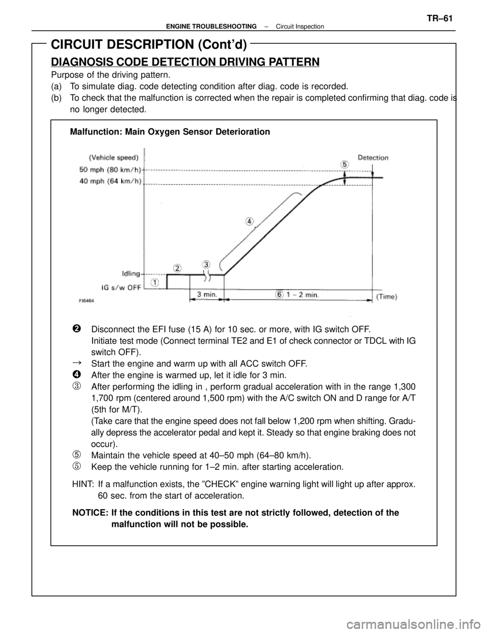
CIRCUIT DESCRIPTION (Cont'd)
DIAGNOSIS CODE DETECTION DRIVING PATTERN
Purpose of the driving pattern.
(a) To simulate diag. code detecting condition after diag. code is recorded.
(b) To check that the malfunction is corrected when the repair is completed co\
nfirming that diag. code isno longer detected.
�Disconnect the EFI fuse (15 A) for 10 sec. or more, with IG switch OFF\
.
Initiate test mode (Connect terminal TE2 and E1 of check connector or TDCL with IG
switch OFF).
�Start the engine and warm up with all ACC switch OFF.
�After the engine is warmed up, let it idle for 3 min.
�After performing the idling in , perform gradual acceleration with in th\
e range 1,300
1,700 rpm (centered around 1,500 rpm) with the A/C switch ON and D range fo\
r A/T
(5th for M/T).
(Take care that the engine speed does not fall below 1,200 rpm when shifting.\
Gradu-
ally depress the accelerator pedal and kept it. Steady so that engine br\
aking does not
occur).
�Maintain the vehicle speed at 40±50 mph (64±80 km/h).
�Keep the vehicle running for 1±2 min. after starting acceleration.
HINT: If a malfunction exists, the ºCHECKº engine warning light will light\
up after approx. 60 sec. from the start of acceleration.
NOTICE: If the conditions in this test are not strictly followed, detection of t\
he malfunction will not be possible.
Malfunction: Main Oxygen Sensor Deterioration
±
ENGINE TROUBLESHOOTING Circuit InspectionTR±61
WhereEverybodyKnowsYourName
Page 3462 of 4087

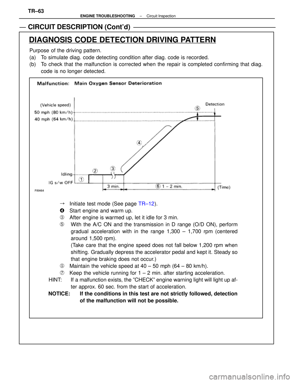
CIRCUIT DESCRIPTION (Cont'd)
Purpose of the driving pattern.
(a) To simulate diag. code detecting condition after diag. code is recorded.
(b) To check that the malfunction is corrected when the repair is completed confirming that diag.code is no longer detected.
DIAGNOSIS CODE DETECTION DRIVING PATTERN
��Initiate test mode (See page TR±12).
��Start engine and warm up.
��After engine is warmed up, let it idle for 3 min.
�With the A/C ON and the transmission in D range (O/D ON), perform
gradual acceleration with in the range 1,300 ± 1,700 rpm (centered
around 1,500 rpm).
(Take care that the engine speed does not fall below 1,200 rpm when
shifting. Gradually depress the accelerator pedal and kept it. Steady so
that engine braking does not occur.)
��Maintain the vehicle speed at 40 ± 50 mph (64 ± 80 km/h).
��Keep the vehicle running for 1 ± 2 min. after starting acceleration.
HINT: If a malfunction exists, the ºCHECKº engine warning light will light\
up af-
ter approx. 60 sec. from the start of acceleration.
NOTICE: If the conditions in this test are not strictly followed, detection of the malfunction will not be possible.
TR±63
±
ENGINE TROUBLESHOOTING Circuit Inspection
WhereEverybodyKnowsYourName